traction control MINI Hardtop 2 Door 2015 Owner's Manual (Mini Connected)
[x] Cancel search | Manufacturer: MINI, Model Year: 2015, Model line: Hardtop 2 Door, Model: MINI Hardtop 2 Door 2015Pages: 244, PDF Size: 11.11 MB
Page 74 of 244

The selected gear is briefly displayed in the in‐
strument cluster, followed by the currently se‐
lected gear.
Manual mode M/S: prevent automatic
upshifting
Once maximum engine speed is attained, M/S
manual mode is automatically upshifted as
needed.
For vehicles with Steptronic Sport transmission,
automatic shift operations are not performed if
one of the following conditions is met:▷DSC is deactivated.▷TRACTION is activated.
In addition, the kickdown is deactivated.
With the respective transmission version, the
lowest possible gear can be selected by simul‐
taneously operating the kickdown and the left
shift paddle. However, this effect is not pro‐
duced via the shift paddles when switching
briefly from D to manual mode.
Ending the sport program/manual
mode
Push the selector lever to the right.
D is displayed in the instrument cluster.
Shift paddles for Steptronic Sport
transmission
The shift paddles on the steering wheel allow
you to shift gears quickly while keeping both
hands on the steering wheel.
▷Shift up: briefly pull right shift paddle.▷Shift down: briefly pull left shift paddle.▷With the respective transmission version,
the lowest possible gear can be selected by
pulling and holding the left shift paddle.
Gears will only be shifted at appropriate engine
and road speeds, for example downshifting is
not possible if the engine speed is too high.
The selected gear is briefly displayed in the in‐
strument cluster, followed by the current gear.
If the shift paddles on the steering wheel are
used to shift gears in automatic mode, the
transmission temporarily switches to manual
mode.
If the selector lever is still in selector lever posi‐
tion D with the respective transmission version,
it is possible to switch back into the automatic
mode:
▷Pull and hold right shift paddle.
Or▷In addition to the briefly pulled right shift
paddle, briefly pull the left shift paddle.
In the manual mode, after conservative driving
for a certain amount of time or if there has
been no acceleration or shifting of the shift
paddles within a certain amount of time, the
transmission switches back to automatic mode.
Displays in the instrument cluster The selector lever position is dis‐
played, e.g.: P.
Manually release the transmission lock Should the selector lever be blocked in selector
lever position P despite the ignition being
turned on, the brake being depressed and the
unlock button being pressed, the transmission
lock can be manually canceled:
Seite 70CONTROLSDriving70
Online Edition for Part no. 01 40 2 961 168 - II/15
Page 75 of 244

Before unlocking the transmission lock man‐
ually, engage the parking brake forcefully to
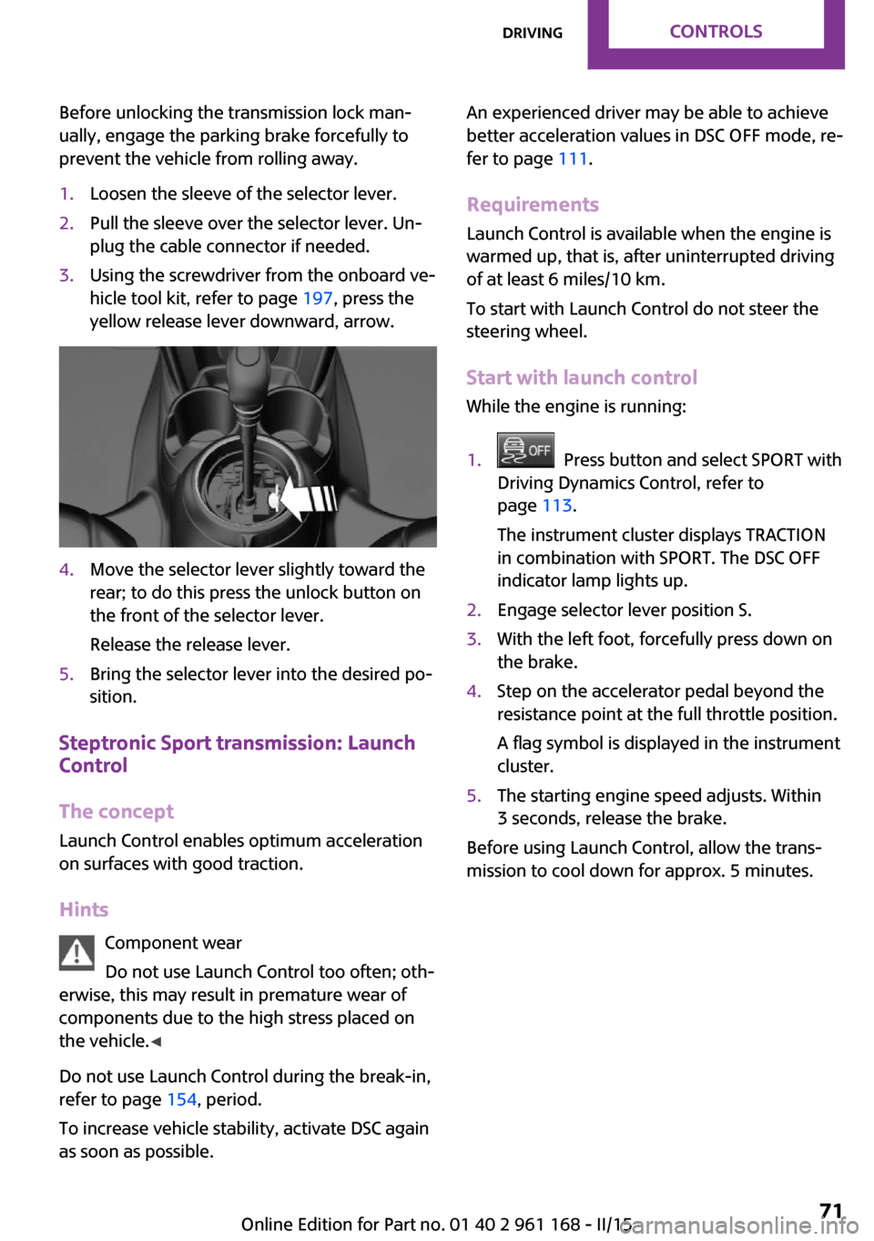
prevent the vehicle from rolling away.1.Loosen the sleeve of the selector lever.2.Pull the sleeve over the selector lever. Un‐
plug the cable connector if needed.3.Using the screwdriver from the onboard ve‐
hicle tool kit, refer to page 197, press the
yellow release lever downward, arrow.4.Move the selector lever slightly toward the
rear; to do this press the unlock button on
the front of the selector lever.
Release the release lever.5.Bring the selector lever into the desired po‐
sition.
Steptronic Sport transmission: Launch
Control
The concept
Launch Control enables optimum acceleration
on surfaces with good traction.
Hints Component wear
Do not use Launch Control too often; oth‐
erwise, this may result in premature wear of
components due to the high stress placed on
the vehicle. ◀
Do not use Launch Control during the break-in,
refer to page 154, period.
To increase vehicle stability, activate DSC again
as soon as possible.
An experienced driver may be able to achieve
better acceleration values in DSC OFF mode, re‐
fer to page 111.
Requirements Launch Control is available when the engine is
warmed up, that is, after uninterrupted driving
of at least 6 miles/10 km.
To start with Launch Control do not steer the
steering wheel.
Start with launch control
While the engine is running:1. Press button and select SPORT with
Driving Dynamics Control, refer to
page 113.
The instrument cluster displays TRACTION
in combination with SPORT. The DSC OFF
indicator lamp lights up.2.Engage selector lever position S.3.With the left foot, forcefully press down on
the brake.4.Step on the accelerator pedal beyond the
resistance point at the full throttle position.
A flag symbol is displayed in the instrument
cluster.5.The starting engine speed adjusts. Within
3 seconds, release the brake.
Before using Launch Control, allow the trans‐
mission to cool down for approx. 5 minutes.
Seite 71DrivingCONTROLS71
Online Edition for Part no. 01 40 2 961 168 - II/15
Page 79 of 244

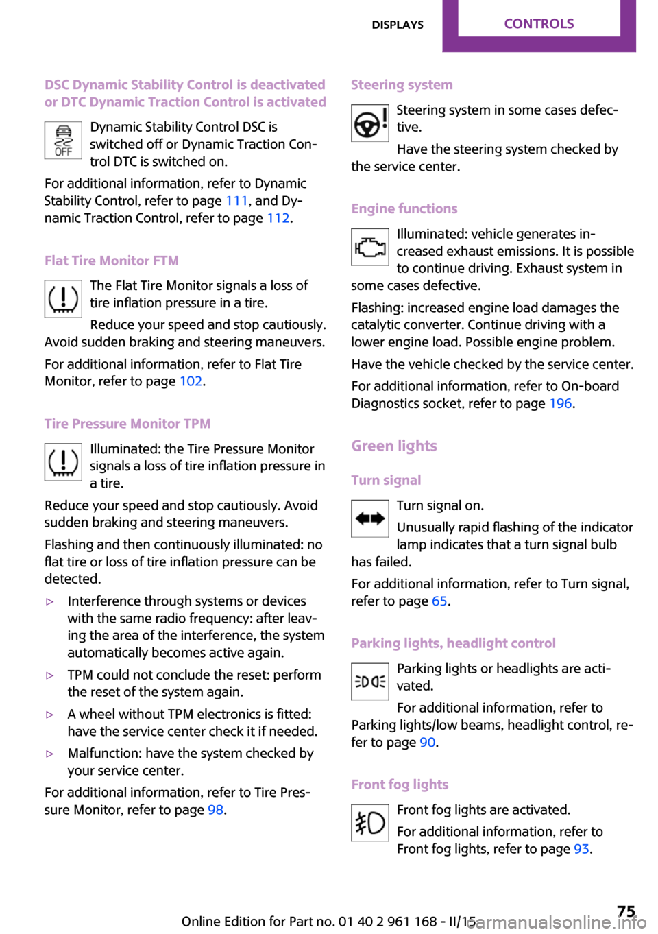
DSC Dynamic Stability Control is deactivated
or DTC Dynamic Traction Control is activated
Dynamic Stability Control DSC is
switched off or Dynamic Traction Con‐
trol DTC is switched on.
For additional information, refer to Dynamic
Stability Control, refer to page 111, and Dy‐
namic Traction Control, refer to page 112.
Flat Tire Monitor FTM The Flat Tire Monitor signals a loss of
tire inflation pressure in a tire.
Reduce your speed and stop cautiously.
Avoid sudden braking and steering maneuvers.
For additional information, refer to Flat Tire
Monitor, refer to page 102.
Tire Pressure Monitor TPM Illuminated: the Tire Pressure Monitor
signals a loss of tire inflation pressure in
a tire.
Reduce your speed and stop cautiously. Avoid
sudden braking and steering maneuvers.
Flashing and then continuously illuminated: no
flat tire or loss of tire inflation pressure can be
detected.▷Interference through systems or devices
with the same radio frequency: after leav‐
ing the area of the interference, the system
automatically becomes active again.▷TPM could not conclude the reset: perform
the reset of the system again.▷A wheel without TPM electronics is fitted:
have the service center check it if needed.▷Malfunction: have the system checked by
your service center.
For additional information, refer to Tire Pres‐
sure Monitor, refer to page 98.
Steering system
Steering system in some cases defec‐tive.
Have the steering system checked by
the service center.
Engine functions Illuminated: vehicle generates in‐
creased exhaust emissions. It is possible
to continue driving. Exhaust system in
some cases defective.
Flashing: increased engine load damages the
catalytic converter. Continue driving with a
lower engine load. Possible engine problem.
Have the vehicle checked by the service center.
For additional information, refer to On-board
Diagnostics socket, refer to page 196.
Green lights
Turn signal Turn signal on.
Unusually rapid flashing of the indicator
lamp indicates that a turn signal bulb
has failed.
For additional information, refer to Turn signal,
refer to page 65.
Parking lights, headlight control Parking lights or headlights are acti‐
vated.
For additional information, refer to
Parking lights/low beams, headlight control, re‐
fer to page 90.
Front fog lights Front fog lights are activated.
For additional information, refer to
Front fog lights, refer to page 93.Seite 75DisplaysCONTROLS75
Online Edition for Part no. 01 40 2 961 168 - II/15
Page 90 of 244

▷Arrow 3: warning field.
Switching on/off LED ring
1. "Settings"2."Center Instrument"3."Center Instrument"
Adjusting the LED ring
1. "Settings"2."Center Instrument"3."Basic display" or "Event display"4.Select desired setting.
Setting the brightnessThe brightness can be adjusted when night
lighting is active in the instrument cluster.
1. "Settings"2."Center Instrument"3."Brightness"4.Turn the controller.
Settings are stored for the profile currently in
use.
Head-up Display
The concept
This system projects important information into
the driver's field of vision, e.g., the speed.
The driver can quickly absorb information and
concentrate on the traffic situation.
Hints
Do not move the moving parts manually
Do not move the moving parts manually,
and keep the area of movement of these parts
clear; otherwise, the system is damaged. ◀
Do not place objects on the Head-up Dis‐
play
Do not place any objects on the Head-up Dis‐
play, attach them to components of the system
or insert them in the system, or else the system
can be damaged. ◀
Keep the closing path clear
Monitor retraction of the projection lens
of the Head-up Display and make sure that the
closing path is clear; otherwise, injuries may re‐
sult. ◀
Follow the instructions for cleaning the Head-
up Display, refer to page 217.
Display visibility
The visibility of the displays in the Head-up Dis‐
play is influenced by the following factors:▷Certain sitting positions.▷Objects on the cover of the Head-up Dis‐
play.▷Sunglasses with certain polarization filters.▷Wet roads.▷Unfavorable light conditions.
Switching on/off
When switching on, the projection lens of the
Head-up Display is extended. When switching
off, the projection lens of the Head-up Display
is retracted again.
Seite 86CONTROLSDisplays86
Online Edition for Part no. 01 40 2 961 168 - II/15
Page 107 of 244

▷When the system has not been initialized.▷When driving on a snowy or slippery road
surface.▷Sporty driving style: spinning traction
wheels, high lateral acceleration (drifting).▷When driving with snow chains.
Actions in the event of a flat tire
Normal tires
1.Identify the damaged tire.
Do this by checking the air pressure in all
four tires.
The tire pressure gauge of the Mobility Sys‐
tem, refer to page 183, can be used for this
purpose.
If the tire inflation pressure in all four tires is
correct, the Flat Tire Monitor may not have
been initialized. In this case, initialize the
system.
If an identification is not possible, please
contact the service center.2.Fix the flat tire using the Mobility System,
refer to page 183.
Run-flat tires
Maximum speed
You may continue driving with a damaged tire at speeds up to 50 mph/80 km/h.
Continued driving with a flat tire
If continuing to drive with a damaged tire:
1.Avoid sudden braking and steering maneu‐
vers.2.Do not exceed a speed of 50 mph/80 km/h.3.Check the air pressure in all four tires at the
next opportunity.
If the tire inflation pressure in all four tires is
correct, the Flat Tire Monitor may not have
been initialized. In this case, initialize the
system.Possible driving distance with complete loss of
tire inflation pressure:
The possible driving distance after a loss of tire
inflation pressure depends on cargo load, driv‐
ing style and road conditions.
A vehicle with an average load has a possible
driving range of approx. 50 miles/80 km.
A vehicle with a damaged tire reacts differently,
e.g., it has reduced lane stability during brak‐
ing, a longer braking distance and different
self-steering properties. Adjust your driving
style accordingly. Avoid abrupt steering ma‐
neuvers or driving over obstacles, e.g., curbs,
potholes, etc.
Because the possible driving distance depends
on how the vehicle is used during the trip, the
actual distance may be shorter or longer de‐
pending on the driving speed, road conditions,
external temperature, cargo load, etc.
Continued driving with a flat tire
Drive moderately and do not exceed a
speed of 50 mph/80 km/h.
Your car handles differently when you lose tire
inflation pressure, e.g., your lane stability is re‐
duced when braking, braking distances are lon‐
ger and the self-steering properties will
change. ◀
Final tire failure
Vibrations or loud noises while driving
can indicate the final failure of a tire. Reduce
speed and stop; otherwise, pieces of the tire
could come loose and cause an accident. Do
not continue driving and contact your service
center. ◀
Intelligent Safety
The concept
Intelligent Safety enables central operation of
the driver assistance system.Seite 103SafetyCONTROLS103
Online Edition for Part no. 01 40 2 961 168 - II/15
Page 115 of 244

Driving stability control systemsVehicle features and op‐
tions
This chapter describes all standard, country-
specific and optional features offered with the
series. It also describes features that are not
necessarily available in your car, e. g., due to
the selected options or country versions. This
also applies to safety-related functions and sys‐
tems. The respectively applicable country provi‐
sions must be observed when using the respec‐
tive features and systems.
Antilock Brake System
ABS
ABS prevents locking of the wheels during
braking.
The vehicle contains its steering power even
during full brake applications, thus increasing
active safety.
ABS is operational every time you start the en‐
gine.
Brake assistant
When you apply the brakes rapidly, this system
automatically produces the greatest possible
braking force boost. It reduces the braking dis‐
tance to a minimum during emergency stop.
This system utilizes all of the benefits provided
by ABS.
Do not reduce the pressure on the brake pedal
for the duration of the emergency stop.DSC Dynamic Stability
Control
The concept
DSC prevents traction loss in the power wheels
when driving off and accelerating.
DSC also recognizes unstable vehicle conditions
such as fishtailing or nose-diving. Within the
physical limits DSC helps to keep the vehicle on
a steady course by reducing engine speed and
by applying brakes to the individual wheels.
Adjust your driving style to the situationAn appropriate driving style is always the
responsibility of the driver.
The laws of physics cannot be repealed, not
even with DSC.
Therefore, do not reduce the additional safety
margin by driving in a risky manner. ◀
Indicator/warning lights The indicator lamp flashes: DSC controls
the drive and braking forces.
The indicator lamp lights up: DSC has
failed.
Deactivating DSC: DSC OFF
When DSC is deactivated, driving stability is re‐
duced during acceleration and when driving in
curves.
To increase vehicle stability, activate DSC again
as soon as possible.
Deactivating DSC Press and hold this button but not lon‐
ger than approx. 10 seconds, until the
indicator lamp for DSC OFF lights up in the in‐
strument cluster and displays DSC OFF.Seite 111Driving stability control systemsCONTROLS111
Online Edition for Part no. 01 40 2 961 168 - II/15
Page 116 of 244

The DSC system is switched off.
Activating DSC Press button.
DSC OFF and the DSC OFF indicator
lamp go out.
Indicator/warning lights
When DSC is deactivated, DSC OFF is displayed
in the instrument cluster.
The indicator lamp lights up: DSC is de‐
activated.
Automatic activation When DSC is deactivated, automatic activation
occurs in the following situations:▷The vehicle has a flat tire.▷When activating cruise control in TRACTION
or DSC OFF mode.
DTC Dynamic Traction
Control
The concept
The DTC system is a version of the DSC where
forward momentum is optimized.
The system ensures maximum headway on
special road conditions or loose road surfaces,
e.g., unplowed snowy roads, but with some‐
what limited driving stability.
Activating the Dynamic Traction Control DTC
provides maximum traction. Driving stability is
limited during acceleration and when driving in
curves.
Therefore drive with appropriate caution.
You may find it useful to briefly activate DTC
under the following special circumstances:
▷When driving in slush or on uncleared,
snow-covered roads.▷When freeing vehicle from deep snow or
driving off from loose grounds.▷When driving with snow chains.
Deactivating/activating DTC Dynamic
Traction Control
Activating DTC Press button.
TRACTION is displayed in the instru‐
ment cluster and the indicator lamp for DSC
OFF lights up.
Deactivating DTC Press button again.
TRACTION and the DSC OFF indicator
lamp go out.
Performance Control
Performance Control enhances the agility of the
vehicle.
To increase maneuverability, with a corre‐
spondingly sporty driving style, wheels are
braked individually.
Dynamic Damping Con‐
trol
The concept
The tuning of the suspension can be changed
with the system.
Programs
The system offers several different programs.
Select the programs via the Driving Dynamics
Control, refer to page 113.
Seite 112CONTROLSDriving stability control systems112
Online Edition for Part no. 01 40 2 961 168 - II/15
Page 120 of 244

At a glance
Buttons on the steering wheelPress buttonFunctionCruise control on/off, interrupt, re‐
fer to page 116Store/maintain speed, refer to
page 117Resume speed, refer to page 117Reduce distance, refer to
page 117Increase distance, refer to
page 117Increase, maintain, and store
speed, refer to page 117Reduce, maintain, and store
speed, refer to page 117
Buttons are arranged according to vehicle's ser‐
ies, optional features and country specifica‐
tions.
Camera
The camera is found near the interior rearview
mirror.
Keep the windshield in the area behind the in‐
terior rearview mirror clean and clear.
Switching on/off and interrupting cruise control
Switching on Press button on the steering wheel.
Display in the instrument cluster lights
up.
Display in the instrument cluster lights up. The current speed is adopted as de‐sired speed and displayed with symbol.
Cruise control can be used.
Switch off Deactivated or interrupted system
With deactivated or interrupted system
use your brakes, steering and moves as usual
to avoid the chance of an accident. ◀
Press button on the steering wheel.▷If active: press twice.▷If interrupted: press once.
The displays go out. The stored desired speed is
deleted.
Interrupting Press button on the steering wheel.
The system is automatically interrupted if:
▷The brakes are applied.▷The clutch pedal is depressed for a few sec‐
onds or released while a gear is not en‐
gaged.▷Selector lever position N is set.▷DTC Dynamic Traction Control is activated
or DSC is deactivated.▷DSC is actively controlling stability.Seite 116CONTROLSDriving comfort116
Online Edition for Part no. 01 40 2 961 168 - II/15
Page 126 of 244

▷Selector lever position N is set.▷DTC Dynamic Traction Control is activated
or DSC is deactivated.▷DSC is actively controlling stability.
Maintaining, storing, and changing the
speed
Hints Adjusting the desired speed
Modify desired speed to road conditions
and be ready to brake at all times; otherwise,
there is the risk of an accident. ◀
Maintaining/storing the speed Press button.
Or
or button: press while the system is in‐
terrupted.
When the system is switched on, the current
speed is maintained and stored as the desired
speed.
This is displayed in the instrument cluster.
When cruise control is maintained or stored,
DSC Dynamic Stability Control will be turned on
if needed.
Changing the speed
or button: press repeatedly until the de‐
sired speed is set.
If active, the displayed speed is stored and the
vehicle reaches the stored speed when the
road is clear.
▷ or button: each time it is pressed to
the point of resistance, the desired speed
increases or decreases by approx.
1 mph/1 km/h.▷ or button: each time it is pressed
past the point of resistance, the desired
speed increases or decreases by a maxi‐
mum of 5 mph/10 km/h.The maximum speed that can be set de‐
pends on the vehicle.▷ or button: pressing it to the resist‐
ance point and holding it there accelerates
or decelerates the vehicle without requiring
pressure on the accelerator pedal. After the
button is released, the vehicle maintains its
final speed. Pressing the switch beyond the
resistance point causes the vehicle to accel‐
erate more rapidly.
Resuming the desired speed
Press button.
The stored speed is reached and maintained.
Displays in the instrument cluster
Indicator lamp Depending on how the vehicle is equip‐
ped, the indicator lamp in the instru‐
ment cluster indicates whether the sys‐
tem is switched on.
Desired speed The desired speed is displayed together
with the symbol.
▷The indicator lights up green: the
system is active.▷The indicator lights up orange: the system
has been interrupted.▷No display: system is switched off.
Brief status display
Selected desired speed.
If --- appears briefly on the display for Check
Control messages, it is possible that the system
requirements are currently not ready for opera‐
tions.
Seite 122CONTROLSDriving comfort122
Online Edition for Part no. 01 40 2 961 168 - II/15
Page 158 of 244

Things to remember when drivingVehicle features and op‐tions
This chapter describes all standard, country-
specific and optional features offered with the
series. It also describes features that are not
necessarily available in your car, e. g., due to
the selected options or country versions. This
also applies to safety-related functions and sys‐
tems. The respectively applicable country provi‐
sions must be observed when using the respec‐
tive features and systems.
Breaking-in period General information Moving parts need time to adjust to one an‐
other (break-in time).
The following instructions will help accomplish
a long vehicle life and good efficiency.
During break-in, do not use the Launch Control,
refer to page 71.
Engine, transmission, and axle drive
Up to 1,200 miles/2,000 km Do not exceed the maximum engine and road
speed:▷For gasoline engine 4,500 rpm and
100 mph/160 km/h.
Avoid full load or kickdown under all circum‐
stances.
From 1,200 miles/2,000 km
The engine and vehicle speed can gradually be
increased.
Tires
Tire traction is not optimal due to manufactur‐
ing circumstances when tires are brand-new;
they achieve their full traction potential after a
break-in time.
Drive conservatively for the first
200 miles/300 km.
Brake system Brakes require an initial break-in period of ap‐
prox. 300 miles/500 km to achieve optimal per‐
formance between brake discs and brake pads.
Drive moderately during this break-in period.
Clutch The function of the clutch reaches its optimal
level only after a distance driven of approx.
300 miles/500 km. During this break-in period,
engage the clutch gently.
Following part replacement The same break-in procedures should be ob‐
served if any of the components above-men‐
tioned have to be renewed in the course of the
vehicle's operating life.
General driving notes
Closing the tailgate Drive with the tailgate closed
Only drive with the tailgate closed; other‐
wise, in the event of an accident or braking and
evasive maneuvers, passengers and other traf‐
fic may be injured, and the vehicle may be
damaged. In addition, exhaust fumes may en‐
ter the vehicle interior. ◀
If driving with the tailgate open cannot be
avoided:Seite 154DRIVING TIPSThings to remember when driving154
Online Edition for Part no. 01 40 2 961 168 - II/15