warning MINI Hardtop 2 Door 2015 Owner's Manual (Mini Connected)
[x] Cancel search | Manufacturer: MINI, Model Year: 2015, Model line: Hardtop 2 Door, Model: MINI Hardtop 2 Door 2015Pages: 244, PDF Size: 11.11 MB
Page 12 of 244

lishment or individual using any certified auto‐
motive part.
California Proposition 65 Warning California laws require us to state the following
warning:
Engine exhaust and a wide variety of automo‐
bile components and parts, including compo‐
nents found in the interior furnishings in a vehi‐
cle, contain or emit chemicals known to the
State of California to cause cancer and birth de‐
fects and reproductive harm. In addition, cer‐
tain fluids contained in vehicles and certain
products of component wear contain or emit
chemicals known to the State of California to
cause cancer and birth defects or other repro‐
ductive harm. Battery posts, terminals and re‐
lated accessories contain lead and lead com‐
pounds. Wash your hands after handling. Used
engine oil contains chemicals that have caused
cancer in laboratory animals. Always protect
your skin by washing thoroughly with soap and
water.
Service and warranty
We recommend that you read this publication
thoroughly. Your vehicle is covered by the fol‐
lowing warranties:▷New Vehicle Limited Warranty.▷Rust Perforation Limited Warranty.▷Federal Emissions System Defect Warranty.▷Federal Emissions Performance Warranty.▷California Emission Control System Limited
Warranty.
Detailed information about these warranties is
listed in the Service and Warranty Information
Booklet for US models or in the Warranty and
Service Guide Booklet for Canadian models.
Your vehicle has been specifically adapted and
designed to meet the particular operating con‐
ditions and homologation requirements in your
country and continental region in order to de‐
liver the full driving pleasure while the vehicle is
operated under those conditions. If you wish to
operate your vehicle in another country or re‐
gion, you may be required to adapt your vehi‐
cle to meet different prevailing operating con‐
ditions and homologation requirements. You
should also be aware of any applicable war‐
ranty limitations or exclusions for such country
or region. In such case, please contact Cus‐
tomer Relations for further information.
Maintenance
Maintain the vehicle regularly to sustain the
road safety, operational reliability and the New
Vehicle Limited Warranty.
Specifications for required maintenance meas‐
ures:▷MINI Maintenance system▷Service and Warranty Information Booklet
for US models▷Warranty and Service Guide Booklet for
Canadian models
If the vehicle is not maintained according to
these specifications, this could result in serious
damage to the vehicle. Such damage is not
covered by the MINI New Vehicle Limited War‐
ranty.
Data memory
Many electronic components on your vehicle
are equipped with data memories that tempo‐
rarily or permanently store technical informa‐
tion about the condition of the vehicle, events
and faults. This technical information generally
records the state of a component, a module, a
system or the environment:
▷Operating mode of system components, fill
levels for instance.▷Status messages for the vehicle and from its
individual components, e.g., wheel rotation
speed/vehicle speed, deceleration, trans‐
verse acceleration.Seite 8Notes8
Online Edition for Part no. 01 40 2 961 168 - II/15
Page 20 of 244

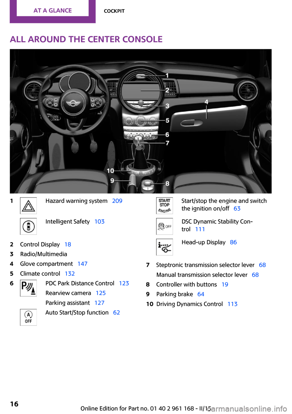
All around the center console1Hazard warning system 209Intelligent Safety 1032Control Display 183Radio/Multimedia4Glove compartment 1475Climate control 1326PDC Park Distance Control 123
Rearview camera 125
Parking assistant 127Auto Start/Stop function 62Start/stop the engine and switch
the ignition on/off 63DSC Dynamic Stability Con‐
trol 111Head-up Display 867Steptronic transmission selector lever 68
Manual transmission selector lever 688Controller with buttons 199Parking brake 6410Driving Dynamics Control 113Seite 16AT A GLANCECockpit16
Online Edition for Part no. 01 40 2 961 168 - II/15
Page 42 of 244

The alarm system, refer to page 43, is dis‐
armed.
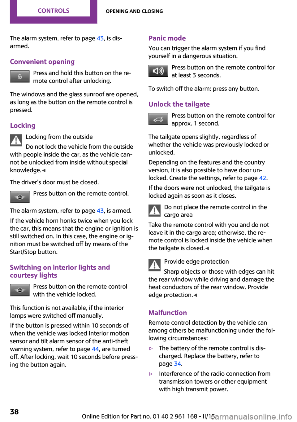
Convenient opening Press and hold this button on the re‐
mote control after unlocking.
The windows and the glass sunroof are opened,
as long as the button on the remote control is
pressed.
Locking Locking from the outside
Do not lock the vehicle from the outside
with people inside the car, as the vehicle can‐
not be unlocked from inside without special
knowledge. ◀
The driver's door must be closed. Press button on the remote control.
The alarm system, refer to page 43, is armed.
If the vehicle horn honks twice when you lock
the car, this means that the engine or ignition is
still switched on. In this case, the engine or ig‐
nition must be switched off by means of the
Start/Stop button.
Switching on interior lights and
courtesy lights
Press button on the remote control
with the vehicle locked.
This function is not available, if the interior
lamps were switched off manually.
If the button is pressed within 10 seconds of
when the vehicle was locked Interior motion
sensor and tilt alarm sensor of the anti-theft
warning system, refer to page 44, are turned
off. After locking, wait 10 seconds before press‐
ing the button again.Panic mode
You can trigger the alarm system if you find
yourself in a dangerous situation.
Press button on the remote control for
at least 3 seconds.
To switch off the alarm: press any button.
Unlock the tailgate Press button on the remote control for
approx. 1 second.
The tailgate opens slightly, regardless of whether the vehicle was previously locked or
unlocked.
Depending on the features and the country
version, it is also possible to have door un‐
locked. Create the settings, refer to page 42.
If the doors were not unlocked, the tailgate is
locked again as soon as it closes.
Do not place the remote control in the
cargo area
Take the remote control with you and do not
leave it in the cargo area; otherwise, the re‐
mote control is locked inside the vehicle when
the tailgate is closed. ◀
Provide edge protection
Sharp objects or those with edges can hit
the rear window while driving and damage the
heat conductors of the rear window. Provide edge protection. ◀
Malfunction Remote control detection by the vehicle can
among others be malfunctioning under the fol‐
lowing circumstances:▷The battery of the remote control is dis‐
charged. Replace the battery, refer to
page 34.▷Interference of the radio connection from
transmission towers or other equipment
with high transmit power.Seite 38CONTROLSOpening and closing38
Online Edition for Part no. 01 40 2 961 168 - II/15
Page 44 of 244

From the inside
Locking and unlocking
Press button.
Vehicle is locked.
Press button.
The vehicle is unlocked.
Pressing the buttons for the central locking sys‐
tem locks and unlocks the doors and the tail‐
gate when the front doors are closed, but they
are not secured against theft.
The fuel filler flap remains unlocked.
In the event of a severe accident, the vehicle is
automatically unlocked. The hazard warning
system and interior lights come on.
Unlocking and opening
Either unlock the doors together using the cen‐
tral locking system buttons and then pull the
door handle above the armrest or pull the door
handle on the door to open the door. The other
doors remain locked.
TailgateHints Keep the closing path clear
Make sure that the closing path of the
tailgate is clear; otherwise, injuries may result. ◀
Do not place the remote control in the
cargo area
Take the remote control with you and do not
leave it in the cargo area; otherwise, the re‐
mote control is locked inside the vehicle when
the tailgate is closed. ◀
Provide edge protection
Sharp objects or those with edges can hit
the rear window while driving and damage the
heat conductors of the rear window. Provide
edge protection. ◀
Opening
When the tailgate is opened, make sure there is
sufficient clearance to prevent damage.▷Unlock the vehicle and press the button on
the tailgate.▷Press button on the remote control
for approx. 1 second.
As the case may be, the doors are also un‐
locked. Unlocking with the remote control,
refer to page 38.
The tailgate is unlocked and can be swung up‐
ward.
Opening from the inside With the vehicle is stationary, press the
button in the driver's footwell.
Seite 40CONTROLSOpening and closing40
Online Edition for Part no. 01 40 2 961 168 - II/15
Page 47 of 244

Tailgate
Depending on optional features and country
version, this setting is not offered in some
cases.1. "Settings"2."Doors/key"3. Select the symbol.4.Select the desired function.▷"Tailgate"
Only the tailgate is unlocked.▷"Tailgate + door(s)"
The tailgate and the doors are un‐
locked.
Locking
The settings are saved in the active profile. Per‐
sonal Profile, refer to page 35.
1. "Settings"2."Doors/key"3.Select desired setting.▷"Lock if no door is opened"
The vehicle locks automatically after a
short period of time if no door is
opened.▷"Lock after start driving"
The vehicle locks automatically after
you drive off.
Confirmation signals from the vehicle
1. "Settings"2."Doors/key"3.Select desired setting.▷"Acoustic sig. lock/unlock"
Unlocking is signaled by one honk of
the horn.▷"Flash when lock/unlock"
Unlocking is signaled by two flashes,
locking by one.Alarm system
The concept
When the vehicle is locked, the vehicle alarm
system responds to:▷Opening a door, the hood or the tailgate.▷Movements in the vehicle interior▷Changes in the vehicle tilt, e. g., during at‐
tempts at stealing a wheel or when towing
the car.▷Disconnected battery voltage.
The alarm system briefly signals tampering:
▷Acoustic alarm.▷By switching on the hazard warning system.▷By flashing the daytime running lights.
Arming and disarming the alarm system
When you lock or unlock the vehicle, either
with the remote control or via the Comfort Ac‐
cess, the alarm system is armed or disarmed at
the same time.
Door lock and armed alarm system
The alarm system is triggered when the door is
opened, when the vehicle is unlocked via the
door lock.
Switch off the alarm, refer to page 44.
Tailgate and armed alarm system The tailgate can be opened even when the
alarm system is armed.
After the tailgate is closed, it is locked and monitored again when the doors are locked.
The hazard warning system flashes once.
Panic mode
You can trigger the alarm system if you find
yourself in a dangerous situation.
Press button on the remote control for
at least 3 seconds.
Seite 43Opening and closingCONTROLS43
Online Edition for Part no. 01 40 2 961 168 - II/15
Page 64 of 244

DrivingVehicle features and op‐
tions
This chapter describes all standard, country-
specific and optional features offered with the
series. It also describes features that are not
necessarily available in your car, e. g., due to
the selected options or country versions. This
also applies to safety-related functions and sys‐
tems. The respectively applicable country provi‐
sions must be observed when using the respec‐
tive features and systems.
Start/Stop button The concept Pressing the Start/Stop button
switches the ignition on or off
and starts the engine.
Steptronic transmission: the en‐
gine starts in selector lever posi‐
tion P or N with the brake pedal pressed when
you press the Start/Stop button.
Manual transmission: the engine starts with the
clutch pedal pressed when the Start/Stop but‐
ton is pressed.
Ignition on Steptronic transmission: press the Start/Stop
button, and do not press on the brake pedal at
the same time.
Manual transmission: press the Start/Stop but‐
ton without stepping on the clutch pedal.
All vehicle systems are ready for operation.
Most of the indicator and warning lights in the
instrument cluster light up for a varied length of
time.To save battery power when the engine is off,
switch off the ignition and any unnecessary
electronic systems/power consumers.
Ignition off
Manual transmission: press the Start/Stop but‐
ton again without stepping on the clutch pedal.
Steptronic transmission: shift to selector lever
position P, press the Start/Stop button again
without stepping on the brake.
All indicator lights in the instrument cluster go
out.
To save battery power when the engine is off,
switch off the ignition and any unnecessary electronic systems/power consumers.
Ignition automatically cuts off while the vehicle
is stationary and the engine is stopped:▷During locking, also with the low beams ac‐
tivated.▷Shortly before the battery is discharged
completely, so that the engine can still be
started. This function is only available when
the low beams are turned off.▷When opening and closing the driver door,
if the driver's safety belt is unbuckled and
the low beams are turned off.▷While the driver's safety belt is unbuckled
with driver's door open and low beams off.▷The low beams switch to parking lights af‐
ter approx. 15 minutes of no use.
Radio ready state
Activate radio-ready state:
▷When the engine is running: press the Start/
Stop button.
Some electronic systems/power consumers re‐
main ready for operation.
Radio ready state switches off automatically:
Seite 60CONTROLSDriving60
Online Edition for Part no. 01 40 2 961 168 - II/15
Page 77 of 244

Electronic displays1Driver assistance systems
Messages, e.g. Check Control
Time 77
External temperature 77
Selection lists 81
Total miles/trip odometer 77On-board computer 812Selector lever position display 68
Gear shift indicator 793Driving Dynamics Control 113
StatusCheck Control
The concept
The Check Control system monitors functions in
the vehicle and notifies you of malfunctions in the monitored systems.
A Check Control message is displayed as a com‐
bination of indicator or warning lights and text
messages in the instrument cluster and in the
Head-up Display.
In addition, an acoustic signal may be output
and a text message may appear on the Control Display.Indicator/warning lights
General information
The indicator and warning lights can light up in
a variety of combinations and colors.
Several of the lights are checked for proper
functioning and light up temporarily when the
engine is started or the ignition is switched on.
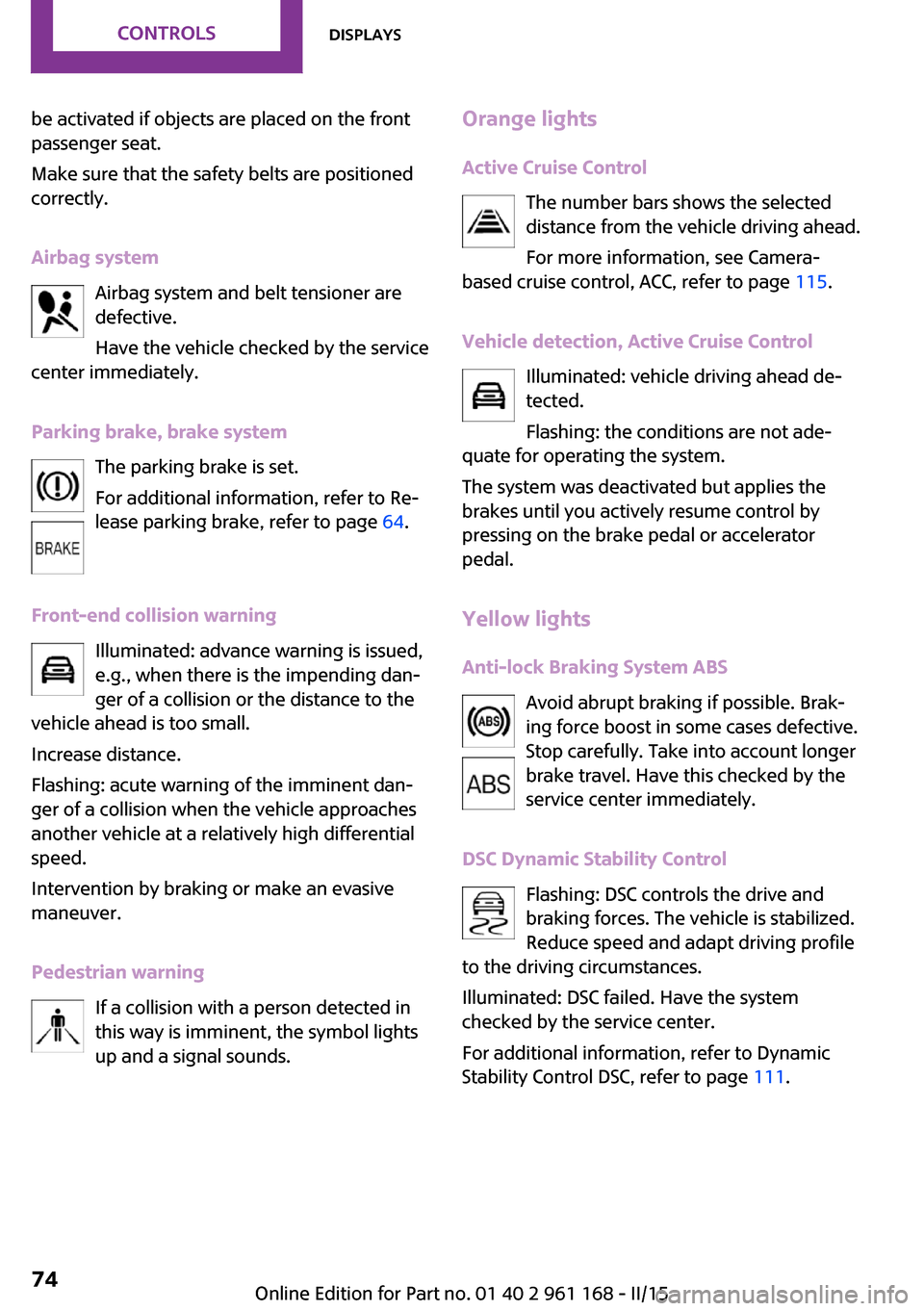
Red lights Safety belt reminder Flashing or illuminated: safety belt on
the driver or passenger side is not buck‐
led. The safety belt reminder can alsoSeite 73DisplaysCONTROLS73
Online Edition for Part no. 01 40 2 961 168 - II/15
Page 78 of 244

be activated if objects are placed on the front
passenger seat.
Make sure that the safety belts are positioned
correctly.
Airbag system Airbag system and belt tensioner are
defective.
Have the vehicle checked by the service
center immediately.
Parking brake, brake system The parking brake is set.
For additional information, refer to Re‐
lease parking brake, refer to page 64.
Front-end collision warning Illuminated: advance warning is issued,
e.g., when there is the impending dan‐
ger of a collision or the distance to the
vehicle ahead is too small.
Increase distance.
Flashing: acute warning of the imminent dan‐
ger of a collision when the vehicle approaches
another vehicle at a relatively high differential
speed.
Intervention by braking or make an evasive
maneuver.
Pedestrian warning If a collision with a person detected in
this way is imminent, the symbol lights
up and a signal sounds.Orange lights
Active Cruise Control The number bars shows the selected
distance from the vehicle driving ahead.
For more information, see Camera-
based cruise control, ACC, refer to page 115.
Vehicle detection, Active Cruise Control Illuminated: vehicle driving ahead de‐
tected.
Flashing: the conditions are not ade‐
quate for operating the system.
The system was deactivated but applies the
brakes until you actively resume control by
pressing on the brake pedal or accelerator
pedal.
Yellow lights Anti-lock Braking System ABS Avoid abrupt braking if possible. Brak‐
ing force boost in some cases defective.
Stop carefully. Take into account longer
brake travel. Have this checked by the
service center immediately.
DSC Dynamic Stability Control Flashing: DSC controls the drive and
braking forces. The vehicle is stabilized.
Reduce speed and adapt driving profile
to the driving circumstances.
Illuminated: DSC failed. Have the system
checked by the service center.
For additional information, refer to Dynamic
Stability Control DSC, refer to page 111.Seite 74CONTROLSDisplays74
Online Edition for Part no. 01 40 2 961 168 - II/15
Page 80 of 244

High-beam AssistantHigh-beam Assistant is switched on.
High beams are activated and off auto‐
matically as a function of the traffic sit‐
uation.
For additional information, refer to High-beam
Assistant, refer to page 92.
Cruise control The system is switched on. It maintains
the speed that was set using the control
elements on the steering wheel.
Blue lights
High beams High beams are activated.
For additional information, refer to High
beams, refer to page 65.
General lamps At least one Check Control message is
displayed or is stored. The symbol is
shown in the display of the instrument
cluster.
Text messages
Text messages in combination with a symbol in
the instrument cluster explain a Check Control
message and the meaning of the indicator and
warning lights.
Supplementary text messages Additional information, such as on the cause of
an error or the required action, can be called up
via Check Control.
With urgent messages the added text will be
automatically displayed on the Control Display.Symbols
Within the supplementary text, the following
functions can be selected independent of the
check control message.▷ Display additional information about
the Check Control message in the
Integrated Owner's Manual.▷ "Service request"
Contact the service partner.▷ "Roadside Assistance"
Contact Roadside Assistance.
Hiding Check Control messages
Press the onboard computer button on the turn
signal lever.
▷Some Check Control messages are dis‐
played continuously and are not cleared
until the malfunction is eliminated. If sev‐
eral malfunctions occur at once, the mes‐
sages are displayed consecutively.
These messages can be faded for approx.
8 seconds. After this time, they are dis‐
played again automatically.▷Other Check Control messages are faded
automatically after approx. 20 seconds.
They are stored and can be displayed again
later.Seite 76CONTROLSDisplays76
Online Edition for Part no. 01 40 2 961 168 - II/15
Page 81 of 244

Displaying stored Check Control
messages
On the Control Display:1. "Vehicle info"2."Vehicle status"3. "Check Control"4.Select the text message.
Messages after trip completion
Special messages displayed while driving are
displayed again after the ignition is switched
off.
Fuel gauge Vehicle tilt position may cause
the display to vary.
The arrow beside the fuel pump
symbol shows which side of the
vehicle the fuel filler flap is on.
Notes on refueling, refer to page 170.
Tachometer Always avoid engine speeds in the red warning
field. In this range, the fuel supply is interrupted
to protect the engine.
Odometer and trip odom‐
eter
The concept
Odometer and trip odometer are displayed in
the instrument cluster.
Resetting the trip odometer
Press the knob.▷The odometer is displayed
when the ignition is switched
off.▷When the ignition is switched
on, the trip odometer is re‐
set.
External temperature
If the indicator drops to
+37 ℉/+3 ℃, a signal sounds.
A Check Control message is dis‐
played.
There is an increased risk of ice
on roads.
Ice on roads
Even at temperatures above
+37 ℉/+3 ℃, roads might be icy.
Therefore, drive carefully on bridges and
shaded roads, e.g., to avoid the increased risk
of an accident. ◀
Time The time is displayed in the in‐
strument cluster.
Setting the time on the Control
Display, refer to page 84.
Date The date is displayed in the in‐
strument cluster.
Set the date on the Control Dis‐
play, refer to page 84.
Seite 77DisplaysCONTROLS77
Online Edition for Part no. 01 40 2 961 168 - II/15