remote control MINI Hardtop 2 Door 2015 User Guide
[x] Cancel search | Manufacturer: MINI, Model Year: 2015, Model line: Hardtop 2 Door, Model: MINI Hardtop 2 Door 2015Pages: 251, PDF Size: 11.4 MB
Page 36 of 251

ClosingKeep the closing path clear
Monitor closing and make sure that the
closing path of the window is clear; otherwise,
injuries may result. ◀
Pull switch up.
The window closes while the reel is held.
See also: closing by means of Comfort Access, refer to page 28.
Pinch protection system Danger of jamming even with pinch pro‐
tection
Even with the pinch protection system, check
that the window's closing path is clear; other‐
wise, the closing action may not stop in certain
situations, e.g., if thin objects are present. ◀
No window accessories
Do not install any accessories in the win‐
dow's range of movement; otherwise, the
pinch protection system will be impaired. ◀
If closing force exceeds a specific margin as a
window closes, closing is interrupted.
The window reopens slightly.
Closing without the pinch protection
system
Keep the closing path clear
Monitor closing and make sure that the
closing path of the window is clear; otherwise,
injuries may result. ◀
E. g. danger from the outside or ice might pre‐
vent window from closing properly - proceed as
follows:1.Pull the switch past the resistance point and
hold it there.
The pinch protection is limited and the win‐
dow reopens slightly if the closing force ex‐
ceeds a certain margin.2.Pull the switch past the resistance point
again within approx. 4 seconds and hold it
there.
The window closes without jam protection.
On 5-door models: safety switch The safety switch in the driver's door can be
used to prevent children, e.g., from opening
and closing the rear windows using the
switches in the rear.
Switching on and off Press button.
The LED lights up if the safety function
is switched on.
Safety switch for rear operation
Press the safety switch when transporting
children in the rear; otherwise, injury may result
if the windows are closed without supervi‐
sion. ◀
Panoramic glass sun‐
roof
Hints Keep the closing path clear
Monitor closing and make sure that the
closing path of the glass sunroof is clear; other‐
wise, injuries may result. ◀
Take the remote control with you
Take the remote control with you when
leaving the vehicle so that children, e.g., cannot
operate the glass sunroof and injure them‐
selves. ◀
Seite 32CONTROLSOpening and closing32
Online Edition for Part no. 01 40 2 961 140 - II/15
Page 52 of 251

▷After approx. 8 minutes.▷When the vehicle is locked using the central
locking system.▷Shortly before the battery is discharged
completely, so that the engine can still be
started.
The radio-ready state remains active if, e.g., the
ignition is automatically switched off for the fol‐
lowing reasons:
▷Opening or closing the driver's door.▷Unfastening of the driver's safety belt.▷When automatically switching from low
beams to parking lights.
If the engine is switched off and the ignition is
switched on, the system automatically switches
to the radio-ready state if the lights are turned
off or, if correspondingly equipped, the day‐
time running lights are activated.
Starting the engine
Hints Enclosed areas
Do not let the engine run in enclosed
areas, since breathing in exhaust fumes may
lead to loss of consciousness and death. The
exhaust gases contain carbon monoxide, an
odorless and colorless but highly toxic gas. ◀
Unattended vehicle
Do not leave the vehicle unattended with
the engine running; doing so poses a risk of
danger.
Before leaving the vehicle with the engine run‐
ning, set the parking brake and place the trans‐
mission in selector lever position P or N to pre‐
vent the vehicle from moving. ◀
Repeated starting in quick succession
Avoid trying to start the vehicle repeat‐
edly and in quick succession. Otherwise, the
fuel is not burned or is inadequately burned,
posing a risk of overheating and damage to the
catalytic converter. ◀
Do not wait for the engine to warm-up while
the vehicle remains stationary. Start driving at
moderate engine speeds.
Steptronic transmission
Starting the engine1.Depress the brake pedal.2.Engage selector lever position P or N.3.Press the Start/Stop button.
The ignition is activated automatically for a cer‐
tain time and is stopped as soon as the engine
starts.
Manual transmission
Starting the engine
1.Depress the brake pedal.2.Press on the clutch pedal and shift to neu‐
tral.3.Press the Start/Stop button.
The ignition is activated automatically for a cer‐
tain time and is stopped as soon as the engine
starts.
Engine stop
Hints Take the remote control with you
Take the remote control with you when
leaving the vehicle so that children, e.g., cannot
start the engine. ◀
Apply parking brake and further secure
the vehicle if needed.
Set the parking brake firmly when parking; oth‐
erwise, the vehicle could roll. On steep upward
and downward inclines, further secure the ve‐
Seite 48CONTROLSDriving48
Online Edition for Part no. 01 40 2 961 140 - II/15
Page 69 of 251

Displaying the cruising range1. Press button.2. "Settings"3."Instrument cluster display"4."Range"
Current fuel consump‐
tion
The concept
Displays the current fuel consumption. Check
whether you are currently driving in an efficient
and environmentally-friendly manner.
Service requirements
The concept
After the ignition is turned on the instrument
cluster briefly displays available driving distance
or time to the next scheduled maintenance.
Your service specialist can read the current
service requirements from your remote control.
Display
Detailed information on service
requirements
The radio will display detailed information
about service requirements.
1. Press button.2. "Vehicle Info"3."Vehicle status"4."Service required"5.Select the desired entry to view detailed in‐
formation.SymbolsSymbolsDescriptionNo service is currently required.The deadline for scheduled
maintenance or a legally man‐
dated inspection is approach‐
ing.The service deadline has al‐
ready passed.
Entering appointment dates
Enter the dates for the required inspections.
Make sure that the vehicle's date and time are
set correctly.
1. Press button.2. "Vehicle Info"3."Vehicle status"4."Service required"5."§ Vehicle inspection" or"§ Emission
inspection"6."Change date"7.Enter the desired appointment.
Gear shift indicator
The concept
The system recommends the most fuel efficient
gear for the current driving situation.
Depending on the vehicle's features and coun‐
try version of the vehicle, the gear shift indica‐
tor is active in the manual mode of the Step‐
tronic transmission and with manual
transmission.
Suggestions to shift gear up or down are dis‐
played in the instrument cluster.
Seite 65DisplaysCONTROLS65
Online Edition for Part no. 01 40 2 961 140 - II/15
Page 123 of 251
Interior equipmentVehicle features and op‐
tions
This chapter describes all standard, country-
specific and optional features offered with the
series. It also describes features that are not
necessarily available in your car, e. g., due to
the selected options or country versions. This
also applies to safety-related functions and sys‐
tems. The respectively applicable country provi‐
sions must be observed when using the respec‐
tive features and systems.
Universal Integrated Re‐
mote Control
The concept
The Universal Integrated Remote Control can
operate up to 3 functions of remote-controlled
systems such as garage door drives or lighting
systems. The Universal Integrated Remote Con‐
trol replaces up to 3 different hand-held trans‐
mitters. To operate the remote control, the but‐
tons on the interior rearview mirror must be
programmed with the desired functions. The
hand-held transmitter for the particular system
is required in order to program the remote con‐
trol.
During programming
During programming and before activat‐
ing a device using the universal garage door
opener, ensure that there are no people, ani‐
mals or objects in the area of the remote-con‐
trolled device; otherwise, there is a risk of injury
or damage.
Also follow the safety instructions of the hand-
held transmitter. ◀
Before selling the vehicle, delete the stored
functions for the sake of security.Compatibility
If this symbol is printed on the packag‐
ing or in the instructions of the system
to be controlled, the system is generally
compatible with the Universal Integrated Re‐
mote Control.
If you have any questions, please contact:▷Your service center.▷www.homelink.com on the Internet.
HomeLink is a registered trademark of Gentex
Corporation.
At a glance
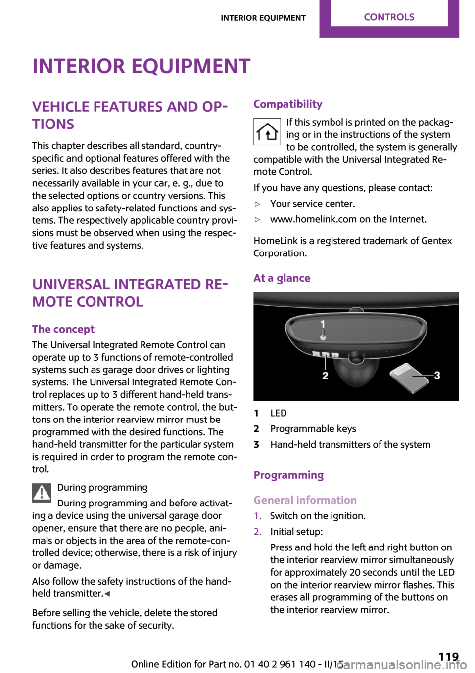
1LED2Programmable keys3Hand-held transmitters of the system
Programming
General information
1.Switch on the ignition.2.Initial setup:
Press and hold the left and right button on
the interior rearview mirror simultaneously
for approximately 20 seconds until the LED
on the interior rearview mirror flashes. This
erases all programming of the buttons on
the interior rearview mirror.Seite 119Interior equipmentCONTROLS119
Online Edition for Part no. 01 40 2 961 140 - II/15
Page 124 of 251
3.Hold the hand-held transmitter for the sys‐
tem to be controlled approx. 1 to 3 in/2.5
to 8 cm away from the buttons of the inte‐
rior rearview mirror. The required distance
depends on the manual transmitter.4.Simultaneously press and hold the button
of the desired function on the hand-held
transmitter and the button to be program‐
med on the interior rearview mirror. The
LED on the interior rearview mirror will be‐
gin flashing slowly.5.Release both buttons as soon as the LED
flashes more rapidly. The LED flashing
faster indicates that the button on the inte‐
rior rearview mirror has been programmed.
If the LED does not flash faster after at least
60 seconds, change the distance between
the interior rearview mirror and the hand-
held transmitter and repeat the step. Sev‐
eral more attempts at different distances
may be necessary. Wait at least 15 seconds
between attempts.
Canada: if programming with the hand-
held transmitter was interrupted, hold
down the interior rearview mirror button
and repeatedly press and release the hand-
held transmitter button for 2 seconds.6.To program other functions on other but‐
tons, repeat steps 3 to 5.
The systems can be controlled using the interior
rearview mirror buttons.
Special feature of the alternating-code
wireless system
If you are unable to operate the system after
repeated programming, please check if the sys‐
tem to be controlled features an alternating-
code system.
Read the system's operating manual, or press
the programmed button on the interior rear‐
view mirror longer. If the LED on the interior
rearview mirror starts flashing rapidly and then
stays lit constantly for 2 seconds, the system
features an alternating-code system. Flashing
and continuous illumination of the LED will re‐
peat for approximately 20 seconds.
For systems with an alternating-code system,
the Universal Integrated Remote Control and
the system also have to be synchronized.
Please read the operating manual to find out
how to synchronize the system.
Synchronizing is easier with the aid of a second
person.
To synchronize:1.Park the vehicle within range of the re‐
mote-controlled system.2.Program the relevant button on the interior
rearview mirror as described.3.Locate and press the synchronizing button
on the system being programmed. You
have approx. 30 seconds for the next step.4.Hold down the programmed button on the
interior rearview mirror for approximately
3 seconds and then release it. If necessary,
repeat this step up to three times in order
to finish synchronization. Once synchroni‐
zation is complete, the programmed func‐
tion will be carried out.
Reprogramming individual buttons
1.Switch on the ignition.2.Press and hold the interior rearview mirror
button to be programmed.3.As soon as the interior rearview mirror LED
starts flashing slowly, hold the hand-held
transmitter for the system to be controlled
approx. 1 to 3 in/2.5 to 8 cm away from the
buttons of the interior rearview mirror. The
required distance depends on the manual
transmitter.4.Likewise, press and hold the button of the
desired function on the hand-held trans‐
mitter.5.Release both buttons as soon as the interior
rearview mirror LED flashes more rapidly.
The LED flashing faster indicates that theSeite 120CONTROLSInterior equipment120
Online Edition for Part no. 01 40 2 961 140 - II/15
Page 125 of 251
button on the interior rearview mirror has
been programmed. The system can then be
controlled by the button on the interior
rearview mirror.
If the LED does not flash faster after at least
60 seconds, change the distance and re‐
peat the step. Several more attempts at dif‐
ferent distances may be necessary. Wait at
least 15 seconds between attempts.
Canada: if programming with the hand-
held transmitter was interrupted, hold
down the interior rearview mirror button
and repeatedly press and release the hand-
held transmitter button for 2 seconds.
Controls
Before operation
Before operating a system using the uni‐
versal garage door opener, ensure that there
are no people, animals, or objects within the
range of movement of the remote-controlled
system; otherwise, there is a risk of injury or
damage.
Also follow the safety instructions of the hand-
held transmitter. ◀
The system, such as the garage door, can be
operated using the button on the interior rear‐
view mirror while the engine is running or
when the ignition is started. To do this, hold
down the button within receiving range of the
system until the function is activated. The inte‐
rior rearview mirror LED stays lit while the wire‐
less signal is being transmitted.
Deleting stored functions
Press and hold the left and right button on the
interior rearview mirror simultaneously for ap‐
proximately 20 seconds until the LED flashes
rapidly. All stored functions are deleted. The
functions cannot be deleted individually.
Digital compass
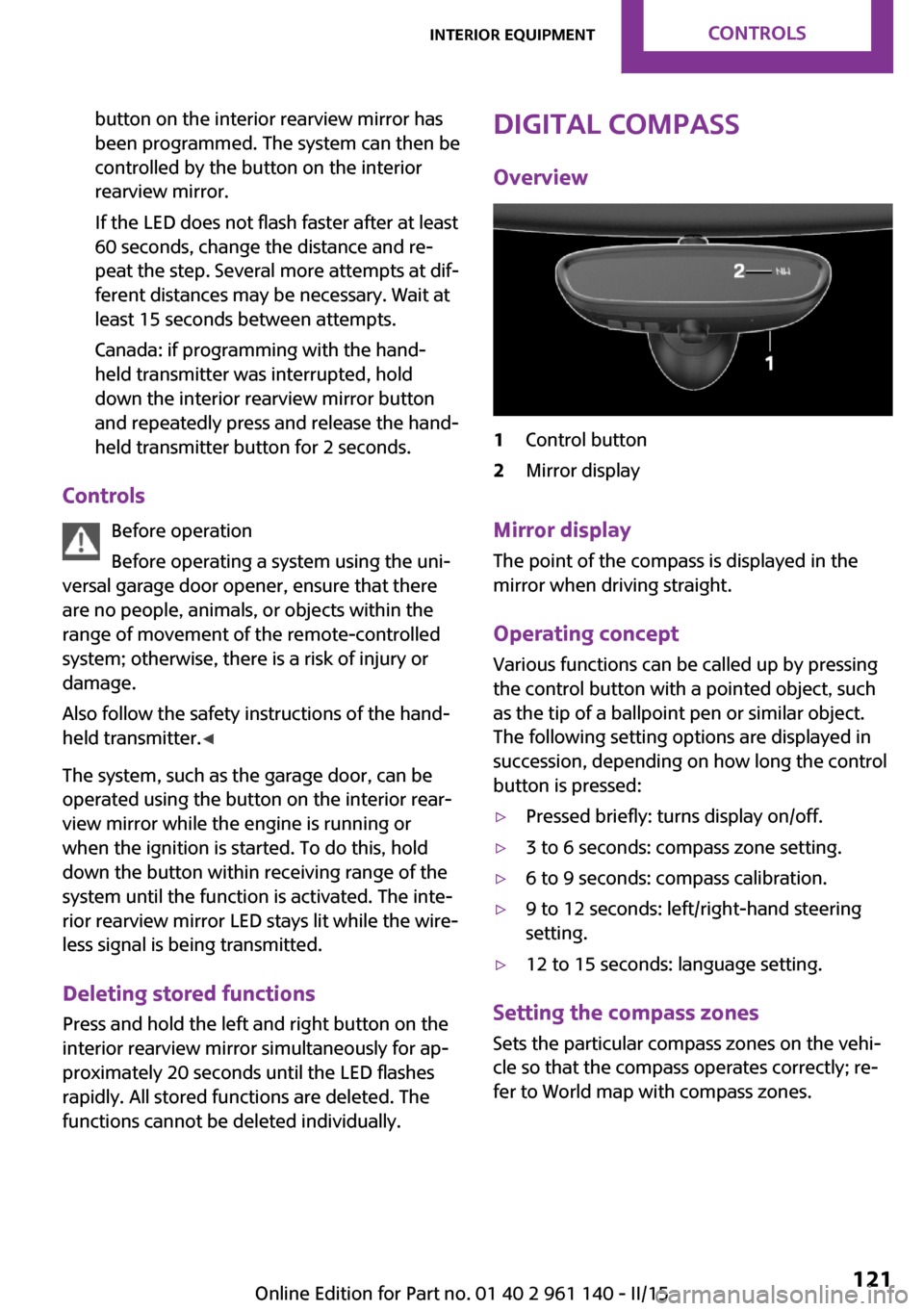
Overview1Control button2Mirror display
Mirror displayThe point of the compass is displayed in the
mirror when driving straight.
Operating concept Various functions can be called up by pressing
the control button with a pointed object, such
as the tip of a ballpoint pen or similar object.
The following setting options are displayed in
succession, depending on how long the control
button is pressed:
▷Pressed briefly: turns display on/off.▷3 to 6 seconds: compass zone setting.▷6 to 9 seconds: compass calibration.▷9 to 12 seconds: left/right-hand steering
setting.▷12 to 15 seconds: language setting.
Setting the compass zones
Sets the particular compass zones on the vehi‐
cle so that the compass operates correctly; re‐
fer to World map with compass zones.
Seite 121Interior equipmentCONTROLS121
Online Edition for Part no. 01 40 2 961 140 - II/15
Page 127 of 251

Settings are stored automatically after approxi‐
mately 10 seconds.
Sun visor
Glare shield
Fold the sun visor down or up.
Vanity mirror
A vanity mirror is located in the sun visor be‐
hind a cover. When the cover is opened, the
mirror lighting switches on.
Ashtray/cigarette
lighter
At a glance
The ashtray is located in one of the frontal cup
holders, the cigarette lighter above it in the
center console.
Ashtray In order to empty the ashtray, remove the ash‐
tray from the cupholder.
Lighter Danger of burns
Only hold the hot lighter by its knob; oth‐
erwise, there is a danger of getting burned.
Switch off the ignition and take the remote
control with you when leaving the vehicle so
that children cannot use the lighter and burn
themselves. ◀
Replace the cover after use
Reinsert the lighter or socket cover after
use, otherwise objects may get into the lighter
socket or fixture and cause a short circuit. ◀
Push in the lighter.
The lighter can be removed as
soon as it pops back out.
Connecting electrical de‐ vices
Hints Do not connect charging devices to the
12 volt socket in the vehicle
Do not connect battery chargers to the factory-
installed 12 volt sockets in the vehicle as this
may damage the vehicle battery due to an in‐
creased power consumption. ◀
Replace the cover after use
Reinsert the lighter or socket cover after
use, otherwise objects may get into the lighter
socket or fixture and cause a short circuit. ◀
Keep the airbag unfolding area clear
Make sure that the devices and cable are
located outside of the airbag's unfolding area;
otherwise, its unfolding can be hampered or
objects can be hurled through the interior
when the airbag unfolds. ◀
Sockets Sockets can be used for the running electrical
devices with the engine running or with the ig‐Seite 123Interior equipmentCONTROLS123
Online Edition for Part no. 01 40 2 961 140 - II/15
Page 157 of 251
The phone number and an electronic serial
number, ESN, are displayed.6.Select the displayed phone number to un‐
subscribe from the channel.
The serial number, ESN, is needed to un‐
subscribe.
Selecting channels
You can only listen to enabled channels.
1. "Radio"2."Satellite radio"3.Select categories.4.Select the channel.
The selected channel is stored in the remote
control currently in use.
Changing the channel Press button.
Storing a channel
1. "Radio"2."Satellite radio"3.Select the channel.4.Press the right button.5.Select the memory location.
The channels are stored for the remote control
currently in use.
The channels can also be stored on the pro‐
grammable memory buttons.
Weather & Traffic jump Traffic and weather information for a selected
region is broadcast every few minutes.
Selecting a region
1. "Radio"2."Satellite radio"3. Press button.4."Set area:"5.Select region.
The region is stored in the remote control cur‐
rently in use.
Activating/deactivating the jump
Reception must be guaranteed in order to acti‐
vate or deactivate.
1. "Radio"2."Satellite radio"3. Press button.4."Weather & Traffic Jump"
Information for the selected region is broadcast
as soon as it is available.
Hints
▷Reception may not be available in some sit‐
uations, such as under certain environmen‐
tal or topographic conditions.▷The signal may not be available in tunnels
or underground garages; next to tall build‐
ings; or near trees, mountains or powerful
sources of radio interference.Seite 153RadioENTERTAINMENT153
Online Edition for Part no. 01 40 2 961 140 - II/15
Page 169 of 251
Rejecting a call
About the radio
"Reject"
Via the instrument cluster
"Reject"
Ending a call About the radio
"End call ( )"
Via the button on the steering wheel
Press button.
Via the instrument cluster
"End call"
Dialing a number
1. "Telephone"2."Dial number"3.Enter numbers using the right rotary knob.4. Select the symbol.
Calls with multiple parties
Accepting a second call
If a second call is received during an ongoing
call, a call waiting signal sounds.
"Accept"
The second call is accepted and the current call
is put on hold.
Establishing a second call Establish an additional call during an active call.
Dial the new phone number or select it from a
list.
▷"Phone book"▷"Outgoing calls"▷"Received calls"The first call is put on hold.
Switching between two calls, hold call You can switch between two calls.
Select line with symbol in order to switch
between the conversations.
Active conversation.
Call on hold.
Establishing/ending a conference call
Two calls can be connected to a single tele‐
phone conference call.
1.Establish two calls.2. "Conference call"
When terminating the conference call, both
calls are ended. If one call is terminated by an‐
other party, the other call is continued if
needed.
Muting the microphone When a call is active, the microphone can be
muted.
"Mute microphone"
The muted microphone is automatically muted:
▷When a new connection is established.▷If using call-switching to switch between
call parties.
DTMF suffix dialing
DTMF suffix dialing can be used for gaining ac‐
cess to network services or for controlling devi‐
ces, e.g., to make a remote inquiry of an an‐
swering machine. The DTMF code is needed for
this purpose. The DTMF code is only available
during an active call.
1."Keypad dialing"2.Enter DTMF code.Seite 165Bluetooth hands-free systemCOMMUNICATION165
Online Edition for Part no. 01 40 2 961 140 - II/15
Page 201 of 251

MaintenanceVehicle features and op‐
tions
This chapter describes all standard, country-
specific and optional features offered with the
series. It also describes features that are not
necessarily available in your car, e. g., due to
the selected options or country versions. This
also applies to safety-related functions and sys‐
tems. The respectively applicable country provi‐
sions must be observed when using the respec‐
tive features and systems.
MINI maintenance system
The maintenance system indicates required
maintenance measures, and thereby provides
support in maintaining road safety and the op‐
erational reliability of the vehicle.
In some cases scopes and intervals may vary
according to the country-specific version. Re‐
placement work, spare parts, fuels and lubri‐
cants and wear materials are calculated sepa‐
rately. Additional information is available from
the service center.
Condition Based Service
CBS
Sensors and special algorithms take into ac‐
count the driving conditions of your vehicle.
Based on this, Condition Based Service recog‐
nizes the maintenance requirements.
The system makes it possible to adapt the
amount of maintenance corresponding to your
user profile.
Detailed information on service requirements,
refer to page 65, can be displayed on the radio.For service data
Information on the required maintenance is
continuously stored in the remote control. Your
service center will read out this data and sug‐
gest the right array of service procedures for
your vehicle.
Therefore, hand your service specialist the re‐
mote control that you used most recently.
Storage periods
Storage periods during which the vehicle bat‐
tery was disconnected are not taken into ac‐
count.
If this occurs, have a service center update the
time-dependent maintenance procedures, such
as checking brake fluid and, if needed, chang‐
ing the engine oil and the microfilter/activated-
charcoal filter.
Service and Warranty In‐
formation Booklet for
US models and Warranty
and Service Guide Book‐
let for Canadian models
Please consult your Service and Warranty Infor‐
mation Booklet for US models and Warranty
and Service Guide Booklet for Canadian models
for additional information on service require‐
ments.
Maintenance and repair should be performed
by your service center. Make sure to have regu‐
lar maintenance procedures recorded in the ve‐
hicle's Service and Warranty Information Book‐
let for US models, and in the Warranty and
Service Guide Booklet for Canadian models.
These entries are proof of regular maintenance.Seite 197MaintenanceMOBILITY197
Online Edition for Part no. 01 40 2 961 140 - II/15