ESP MINI Hardtop 2 Door 2015 Owner's Guide
[x] Cancel search | Manufacturer: MINI, Model Year: 2015, Model line: Hardtop 2 Door, Model: MINI Hardtop 2 Door 2015Pages: 251, PDF Size: 11.4 MB
Page 63 of 251

DisplaysVehicle features and op‐tions
This chapter describes all standard, country-
specific and optional features offered with the
series. It also describes features that are notnecessarily available in your car, e. g., due to
the selected options or country versions. This
also applies to safety-related functions and sys‐
tems. The respectively applicable country provi‐
sions must be observed when using the respec‐
tive features and systems.
Instrument cluster
Overview, instrument cluster
1Tachometer 642Messages, e.g. Check Control3Speedometer4Fuel gauge 645Display/reset miles 646Electronic displays 60Seite 59DisplaysCONTROLS59
Online Edition for Part no. 01 40 2 961 140 - II/15
Page 71 of 251

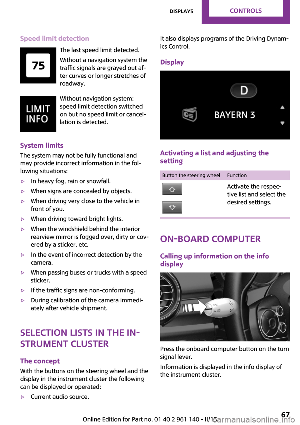
Speed limit detectionThe last speed limit detected.
Without a navigation system the
traffic signals are grayed out af‐
ter curves or longer stretches of
roadway.
Without navigation system:
speed limit detection switched
on but no speed limit or cancel‐
lation is detected.
System limits The system may not be fully functional and
may provide incorrect information in the fol‐
lowing situations:▷In heavy fog, rain or snowfall.▷When signs are concealed by objects.▷When driving very close to the vehicle in
front of you.▷When driving toward bright lights.▷When the windshield behind the interior
rearview mirror is fogged over, dirty or cov‐
ered by a sticker, etc.▷In the event of incorrect detection by the
camera.▷When passing buses or trucks with a speed
sticker.▷If the traffic signs are non-conforming.▷During calibration of the camera immedi‐
ately after vehicle shipment.
Selection lists in the in‐
strument cluster
The concept
With the buttons on the steering wheel and the
display in the instrument cluster the following
can be displayed or operated:
▷Current audio source.It also displays programs of the Driving Dynam‐
ics Control.
Display
Activating a list and adjusting the
setting
Button the steering wheelFunctionActivate the respec‐
tive list and select the
desired settings.
On-board computer
Calling up information on the info
display
Press the onboard computer button on the turn
signal lever.
Information is displayed in the info display of
the instrument cluster.
Seite 67DisplaysCONTROLS67
Online Edition for Part no. 01 40 2 961 140 - II/15
Page 72 of 251

Calling up information in the radioInformation is also shown on the radio display.1. Press button.2. "Vehicle Info"3."Onboard info"
Resetting values
1.Select the desired value.2."Reset?"
Information at a glance
Info display Repeatedly pressing the button
on the turn signal lever calls up the following information in the
info display:
▷Range.▷GREEN Info.
When GREEN Mode is activated.▷Average fuel consumption.▷Current fuel consumption.▷Average speed.▷Date.▷Engine temperature display.▷Speed limit detection.▷Speed.
Radio
Selected information is shown on the radio.
▷Range.▷Average fuel consumption.▷Average speed.Adjusting the info display
You can select what information from the com‐
puter is to be displayed on the info display of
the instrument cluster.1. Press button.2. "Settings"3."Instrument cluster display"4.Select the desired displays.
Information in detail
Range
Displays the estimated cruising range available
with the remaining fuel.
It is calculated based on your driving style over
the last 20 miles/30 km.
GREEN info Description of GREEN info, refer to page 143.
Average fuel consumption
This is calculated for the period while the en‐
gine is running.
The average fuel consumption is calculated for
the distance traveled since the last reset by the
on-board comupter.
Average speed
Periods in which the vehicle is parked with the
engine manually stopped are not included in
the calculation of the average speed.
Resetting average valuesPress and hold the onboard computer button
on the turn signal lever.
Engine temperature display Displays the current engine temperature, based
on a combination of coolant and motor oil tem‐
perature. As soon as the optimum operating
temperature has been attained, the indicator is
in the center position.
Seite 68CONTROLSDisplays68
Online Edition for Part no. 01 40 2 961 140 - II/15
Page 74 of 251

LED ring on the central
instrument cluster
The concept
The LED ring displays light animations to repre‐
sent specific functions.
Basic displays
Basic functions, for example the tachometer,
can be set to be displayed continually if so de‐
sired.
Event displays
Functions that are only displayed temporarily,
for example the volume or temperature set‐
tings, can be set as event displays.
Several vehicle assistance functions can also be
displayed on the LED ring. This display corre‐
sponds with the displays of the function in the
respective display.
Example: tachometer
Like the tachometer in the instrument cluster,
the light animations of the tachometer's basic
display show the current RPMs and the respec‐
tive RPM warning margins.
Display▷Arrow 1: current RPM.▷Arrow 2: prewarning field.▷Arrow 3: warning field.Switching on/off LED ring1. Press button.2. "Settings"3."Center Instrument"4."Center Instrument"
Adjusting the LED ring
1. Press button.2. "Settings"3."Center Instrument"4."Basic display" or "Event display"5.Select desired setting.
Setting the brightness The brightness can be adjusted when night
lighting is active in the instrument cluster.
1. Press button.2. "Settings"3."Center Instrument"4."Brightness"5.Turn the right-hand knob.
Settings are stored for the profile currently in
use.
Chrono package in the
cockpit
The concept
The Chrono package consists of three display
instruments in the cockpit, where the engine oil
pressure, the turbocharger boost, and the time
are displayed. In addition, intermediate and to‐
tal times can be measured using the stop
watch.
The display elements of the Chrono package
mainly support a sporty driving style, e,g, on
racetracks.
Seite 70CONTROLSDisplays70
Online Edition for Part no. 01 40 2 961 140 - II/15
Page 77 of 251

LightsVehicle features and op‐
tions
This chapter describes all standard, country-
specific and optional features offered with the series. It also describes features that are notnecessarily available in your car, e. g., due to
the selected options or country versions. This
also applies to safety-related functions and sys‐
tems. The respectively applicable country provi‐
sions must be observed when using the respec‐
tive features and systems.
Overview1Rear fog lights2Front fog lights3Depending on the equipment: automatic
headlight control, cornering lights, High-
beam Assistant, welcome lights, daytime
running lights4Lights off, daytime running lights5Parking lights / daytime running lights6Depending on the equipment: low beams,
welcome lights, High-beam Assistant7Instrument lightingParking lights, corner‐
ing lights and roadside
parking lights
General information Position of switch:
, ,
If the driver door is opened with the ignition
switched off, the exterior lighting is automati‐
cally switched off at these switch settings.
Parking lights
Position of switch
: the vehicle's lights
light up on all sides, e.g., for parking.
Do not use the parking lights for extended peri‐
ods; otherwise, the battery may become dis‐
charged and it would then be impossible to
start the engine.
When parking you better turn on just the road-
side parking light.
Low beams
Position of switch
with the ignition
switched on: the low beams light up.
Roadside parking lights
The vehicle can be illuminated on one side.
Seite 73LightsCONTROLS73
Online Edition for Part no. 01 40 2 961 140 - II/15
Page 78 of 251

Switching on
With the ignition switched off, press the lever
either up or down past the resistance point for
approx. 2 seconds.
Switch off Briefly press the lever to the resistance point in
the opposite direction.
Welcome lights and
headlight courtesy de‐
lay feature
Welcome lights When the vehicle is parked, leave the switch in
position
or : parking and interior lights
come on briefly when the vehicle is unlocked
depending on the ambient brightness.
Activating/deactivating
Set via radio.
1. Press button.2. "Settings"3."Lighting"4."Welcome light"
Settings are stored for the profile currently in
use.
Headlight courtesy delay feature
The low beams stay lit for a short while after
the radio-ready state is switched off if the lights
are turned off and the headlight flasher is
switched on.
Setting the duration Set via radio.
1. Press button.2. "Settings"3."Lighting"4."Pathway lighting:"5.Set length of time.
Settings are stored for the profile currently in
use.
Automatic headlight
control
Position of switch
: the low beams are acti‐
vated and off automatically, e.g., in tunnels, in
twilight or if there is precipitation. The indicator
lamp in the instrument cluster lights up.
A blue sky with the sun low on the horizon can
cause the lights to be switched on.
The low beams always stay on when the fog
lights are activated.
Personal responsibility
The automatic headlight control cannot
serve as a substitute for your personal judg‐
ment in determining when to turn the lights on
in response to ambient lighting conditions.
E. g. the sensors are unable to detect fog or
hazy weather. To avoid safety risks under these
conditions, you should always switch on the
lights manually. ◀
Daytime running lights
With the ignition switched on, the daytime run‐
ning lights light up in position
, or
. After the ignition is switched off, the park‐
ing lights light up in position
.
Activating/deactivating
In some countries, daytime running lights are
mandatory, so it may not be possible to deacti‐
vate the daytime running lights.
Seite 74CONTROLSLights74
Online Edition for Part no. 01 40 2 961 140 - II/15
Page 79 of 251

Set via radio.1. Press button.2. "Settings"3."Lighting"4."Daytime running lamps"
Settings are stored for the profile currently in
use.
Cornering lamp
Position of switch
: going around corners,
the cornering lamp also lights the interior area
of the curve. Below a speed of approx.
25 mph/40 km/h when the flasher is switched
on and the steering angle is detected, there is
automatic activation.
Malfunction
A Check Control message is displayed.
Cornering light is disrupted or failed. Have the
system checked as soon as possible.
High-beam Assistant The concept
When the low beams are activated, this system
automatically switches the high beams on and
off. The procedure is controlled by a camera on
the front of the interior rearview mirror. The as‐
sistant ensures that the high beams are acti‐
vated whenever the traffic situation allows. The
driver can intervene at any time and switch the
high beams on and off as usual.
Note Personal responsibility
The High-beam Assistant cannot serve as
a substitute for the driver's personal judgment
of when to use the high beams. Therefore,
manually reel off the high beams in situations
where required to avoid a safety risk. ◀
Activating
The High-beam Assistant can be activated
when the low beams are activated.
1.Depending on the equipment, turn the light
switch into position
or .
2.Press button on the turn signal lever, arrow.
The indicator lamp in the instrument
cluster lights up.
When the low beams are on, the lights are au‐
tomatically brightened or dimmed.
The system responds to light from oncoming
traffic and traffic driving ahead of you, and to
adequate illumination, e.g., in towns and cities.
The blue indicator lamp in the instru‐
ment cluster lights up when the system
switches on the high beams.
Switching the high beams on and off
manually
▷High beams on, arrow 1.Seite 75LightsCONTROLS75
Online Edition for Part no. 01 40 2 961 140 - II/15
Page 82 of 251

SafetyVehicle features and op‐
tions
This chapter describes all standard, country-
specific and optional features offered with the
series. It also describes features that are notnecessarily available in your car, e. g., due to
the selected options or country versions. This
also applies to safety-related functions and sys‐
tems. The respectively applicable country provi‐
sions must be observed when using the respec‐
tive features and systems.
Airbags
1Front airbag, driver2Front airbag, front passenger3Head airbag4Side airbag5Knee airbagsFront airbags
Front airbags help protect the driver and front
passenger by responding to frontal impacts in
which safety belts alone would not provide ad‐
equate restraint.Side airbags
In a lateral impact, the side airbag supports the
side of the body in the chest and lap area.
Head airbags
In a lateral impact, the head airbag supports
the head.Seite 78CONTROLSSafety78
Online Edition for Part no. 01 40 2 961 140 - II/15
Page 85 of 251

After installing a child seat, make sure that the
indicator lamp for the front-seat passenger air‐
bags lights up. This indicates that the child seat
has been detected and the front-seat passen‐
ger airbags are not activated.
Strength of the driver's and front-seat
passenger airbag
The explosive power that activates driver's/
front passenger's airbags very much depends
on the positions of the driver's/front passeng‐
er's seat.
With a respective message appearing on Con‐
trol Display calibrate the front seats to keep the
accuracy of this function over the long-term.
Calibrating the front seats
A corresponding message appears on the Con‐
trol Display.1.Move the respective seat all the way for‐
ward.2.Move the respective seat forward again. It
moves forward briefly.3.Readjust the seat to the desired position.
The calibration procedure is completed when
the message on the Control Display disappears.
If the message continues to be displayed, re‐
peat the calibration.
If the message does not disappear after a re‐
peat calibration, have the system checked as
soon as possible.
Unobstructed area of movement
Ensure that the area of movement of the
seats is unobstructed to avoid personal injury
or damage to objects. ◀
Tire Pressure Monitor
TPM
The concept The system monitors tire inflation pressure in
the four mounted tires. The system warns you if
there is a significant loss of pressure in one or
more tires. For this purpose, sensors in the tire
valves measure the tire inflation pressure.
Hints Tire damage due to external factors
Sudden tire damage caused by external
circumstances cannot be recognized in ad‐
vance. ◀
With use of the system observe further infor‐
mation found under Tire inflation pressure, re‐
fer to page 176.
Functional requirements
The system must have been reset with the cor‐
rect tire inflation pressure; otherwise, reliable
signaling of tire pressure loss is not assured.
Reset the system after each adjustment of the
tire inflation pressure and after every tire or
wheel change.
Always use wheels with TPM electronics to en‐
sure that the system will operate properly.
Status display
The current status of the Tire Pressure Monitor
TPM can be displayed, e.g., whether or not the
TPM is active.1. Press button.2. "Vehicle Info"3."Vehicle status"4."Tire Pressure Monitor (TPM)"
The status is displayed.
In addition, the current tire inflation pressures
are displayed. It shows the actual values read;
Seite 81SafetyCONTROLS81
Online Edition for Part no. 01 40 2 961 140 - II/15
Page 88 of 251

▷TPM was unable to complete the reset. Re‐
set the system again.▷Interference through systems or devices
with the same radio frequency: after leav‐
ing the area of the interference, the system
automatically becomes active again.
Declaration according to NHTSA/FMVSS
138 Tire Pressure Monitoring System
Each tire, including the spare (if provided)
should be checked monthly when cold and in‐
flated to the inflation pressure recommended
by the vehicle manufacturer on the vehicle
placard or tire inflation pressure label. (If your
vehicle has tires of a different size than the size
indicated on the vehicle placard or tire inflation
pressure label, you should determine the
proper tire inflation pressure for those tires.) As
an added safety feature, your vehicle has been
equipped with a tire pressure monitoring sys‐
tem (TPMS) that illuminates a low tire pressure
telltale when one or more of your tires is signifi‐
cantly under-inflated. Accordingly, when the
low tire pressure telltale illuminates, you should
stop and check your tires as soon as possible,
and inflate them to the proper pressure. Driving
on a significantly under-inflated tire causes the
tire to overheat and can lead to tire failure. Un‐
der-inflation also reduces fuel efficiency and
tire tread life, and may affect the vehicle's han‐
dling and stopping ability. Please note that the
TPMS is not a substitute for proper tire mainte‐
nance, and it is the driver's responsibility to
maintain correct tire pressure, even if under-in‐
flation has not reached the level to trigger illu‐
mination of the TPMS low tire pressure telltale.
Your vehicle has also been equipped with a
TPMS malfunction indicator to indicate when
the system is not operating properly. The TPMS
malfunction indicator is combined with the low
tire pressure telltale. When the system detects
a malfunction, the telltale will flash for approxi‐
mately one minute and then remain continu‐
ously illuminated. This sequence will continue
upon subsequent vehicle start-ups as long as
the malfunction exists. When the malfunction
indicator is illuminated, the system may not be
able to detect or signal low tire pressure as in‐
tended. TPMS malfunctions may occur for a va‐
riety of reasons, including the installation of re‐
placement or alternate tires or wheels on the
vehicle that prevent the TPMS from functioning
properly. Always check the TPMS malfunction
telltale after replacing one or more tires or
wheels on your vehicle to ensure that the re‐
placement or alternate tires and wheels allow
the TPMS to continue to function properly.
FTM Flat Tire Monitor
The concept The system does not measure the actual infla‐
tion pressure in the tires.
It detects a tire inflation pressure loss by com‐
paring the rotational speeds of the individual
wheels while moving.
In the event of a tire inflation pressure loss, the
diameter and therefore the rotational speed of
the corresponding wheel changes. This will be
detected and reported as a flat tire.
Functional requirements The system must have been initialized when
the tire inflation pressure was correct; other‐
wise, reliable flagging of a flat tire is not as‐
sured. Initialize the system after each correc‐
tion of the tire inflation pressure and after
every tire or wheel change.
Status display
The current status of the flat tire monitor can
be displayed, e.g., whether the RPA is active.1. Press button.2. "Vehicle Info"3."Vehicle status"4."Flat Tire Monitor (FTM)"
The status is displayed.
Seite 84CONTROLSSafety84
Online Edition for Part no. 01 40 2 961 140 - II/15