ignition MINI Hardtop 2 Door 2015 Owner's Guide
[x] Cancel search | Manufacturer: MINI, Model Year: 2015, Model line: Hardtop 2 Door, Model: MINI Hardtop 2 Door 2015Pages: 251, PDF Size: 11.4 MB
Page 83 of 251

Knee airbagThe knee airbag supports the legs in a frontal
impact.
Protective action Airbags are not triggered in every impact situa‐
tion, e.g., in less severe accidents or rear-end
collisions.
Information on how to ensure the opti‐
mal protective effect of the airbags▷Keep at a distance from the airbags.▷Always grasp the steering wheel on the
steering wheel rim, holding your hands at
the 3 o'clock and 9 o'clock positions, to
keep the risk of injury to your hands or
arms as low as possible when the airbag is
triggered.▷There should be no person, animals, or ob‐
jects between an airbag and a person.▷Do not use the cover of the front airbag on
the front passenger side as a storage area.▷Dashboard and windshield on the front
passenger side must stay clear - do not at‐
tach adhesive labels or coverings and do
not attach brackets or cables, e. g., for GPS
devices or' mobile phones.▷Make sure that the front passenger is sitting
correctly, i.e., keeps his or her feet and legs
in the footwell; otherwise, leg injuries might
occur when front airbag is activated.▷Do not place slip covers, seat cushions or
other objects on the front passenger seat
that are not approved specifically for seats
with integrated side airbags.▷Do not hang pieces of clothing, such as
jackets, over the backrests.▷Make sure that occupants keep their heads
away from the side airbag and do not rest
against the head airbag; otherwise, injuries
might occur when airbag is activated.▷Do not remove the airbag system.▷Do not remove the steering wheel.▷Do not apply adhesive materials to the air‐
bag cover panels, do not cover them or
modify them in any way.▷Never modify either the individual compo‐
nents or the wiring in the airbag system.
This also applies to steering wheel covers,
the dashboard, the seats, the roof pillars
and the sides of the roofliner. ◀
Even when you follow all instructions very
closely, injury from contact with the airbags
cannot be ruled out in certain situations.
The ignition and inflation noise may lead to
short-term and, in most cases, temporary hear‐
ing impairment in sensitive individuals.
Malfunction, deactivation and after de‐
ploying the airbags
Do not touch the individual components imme‐
diately after the system has been triggered;
otherwise, you may risk burns.
Only have the airbags checked, repaired or dis‐
mantled and the airbag generator scrapped by
the service center or an authorized repair shop
for handling explosives.
Non-professional attempts to service the sys‐
tem could lead to failure in an emergency or
unintentional activation of the airbag - both
may lead to injury. ◀
Warnings and information on the airbags are
also found on the sun visors.
Functional readiness of the airbag
system
When the ignition is reel on, the warn‐
ing lamp in the instrument cluster lights
up briefly and thereby indicates the op‐
erational readiness of the entire airbag system
and the belt tensioner.
Airbag system malfunctioning
▷Warning lamp does not come on when the
ignition is turned on.▷The warning lamp lights up continuously.Seite 79SafetyCONTROLS79
Online Edition for Part no. 01 40 2 961 140 - II/15
Page 105 of 251
lected distance is briefly displayed in the info
display.
In the following cases, the stored speed value is
deleted and cannot be called up again:▷When the system is switched off.▷When the ignition is switched off.
Changing between cruise control with/
without distance control
Traffic ahead
The cruise control does not react to traffic
driving ahead of you, but instead maintains the
stored speed. Take this factor into account – you yourself must react; otherwise, there is the
risk of an accident. ◀
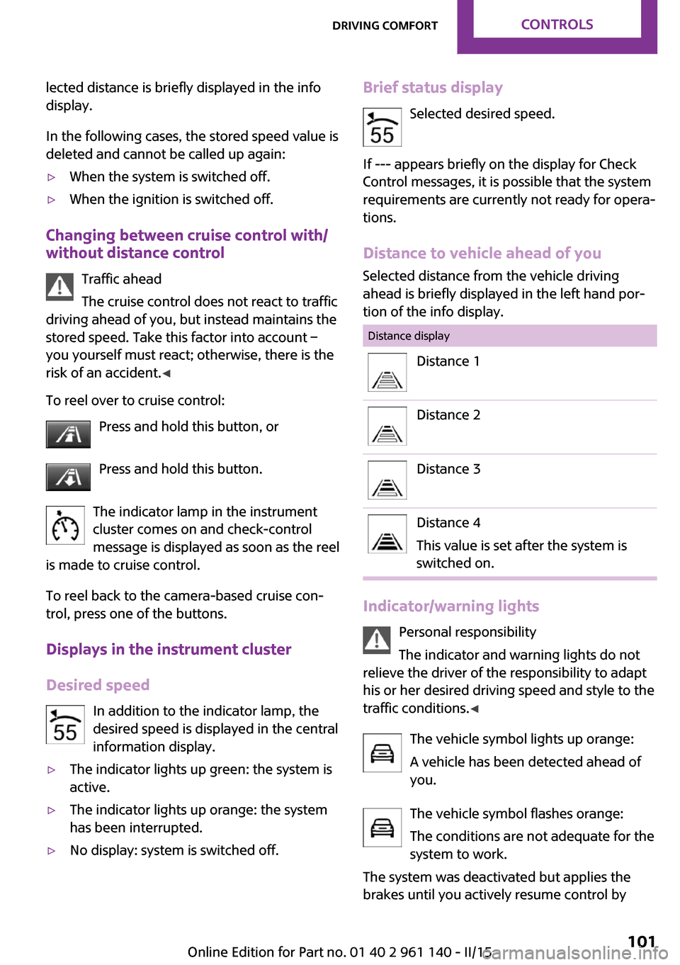
To reel over to cruise control: Press and hold this button, or
Press and hold this button.
The indicator lamp in the instrument
cluster comes on and check-control
message is displayed as soon as the reel
is made to cruise control.
To reel back to the camera-based cruise con‐
trol, press one of the buttons.
Displays in the instrument cluster
Desired speed In addition to the indicator lamp, the
desired speed is displayed in the central
information display.
▷The indicator lights up green: the system is
active.▷The indicator lights up orange: the system
has been interrupted.▷No display: system is switched off.Brief status display
Selected desired speed.
If --- appears briefly on the display for Check
Control messages, it is possible that the system
requirements are currently not ready for opera‐
tions.
Distance to vehicle ahead of you Selected distance from the vehicle driving
ahead is briefly displayed in the left hand por‐
tion of the info display.Distance displayDistance 1Distance 2Distance 3Distance 4
This value is set after the system is
switched on.
Indicator/warning lights
Personal responsibility
The indicator and warning lights do not
relieve the driver of the responsibility to adapt
his or her desired driving speed and style to the
traffic conditions. ◀
The vehicle symbol lights up orange:
A vehicle has been detected ahead of
you.
The vehicle symbol flashes orange:
The conditions are not adequate for the
system to work.
The system was deactivated but applies the
brakes until you actively resume control by
Seite 101Driving comfortCONTROLS101
Online Edition for Part no. 01 40 2 961 140 - II/15
Page 114 of 251

▷Press button.▷Switch off the ignition.
Indicator of the radio display
System status
▷Symbols, see arrows, on the
side of the vehicle illustrated.
Parking assistant is activated
and search for parking space
active.▷Suitable parking spaces are displayed next
to the vehicle symbol at the edge of the
road as on the display.▷The parking procedure is ac‐
tive. Steering control has
been taken over by system.▷Parking space search is always active
whenever the vehicle is moving forward
slow and straight, even if the system is de‐
activated.
Parking using the parking assistant
Check the traffic situation as well
Louds noises outside and inside the vehi‐
cle can drown out the parking assistant's and
PDC's signals.
Check the traffic situation around the vehicle
with your own eyes; otherwise, there is a dan‐
ger of an accident. ◀
1.Switch on the parking assistant and activate
it if needed.
The status of the parking space search is in‐
dicated on the display.2.Follow the instructions on the display.
The best possible parking position will
come after gear change on the stationary
vehicle - wait for the automatic steering
wheel move.The end of the parking procedure is indi‐
cated on the display.3.Adjust the parking position yourself if
needed.
Interrupting manually
The parking assistant can be interrupted at any
time:
▷Press button.
Interrupting automatically
The system is interrupted automatically in the
following situations:
▷If the driver grasps the steering wheel or if
he takes over steering.▷If a gear is selected that does not match the
instruction on the display.▷If the vehicle speed exceeds approx.
6 mph/10 km/h.▷Possible on snow-covered or slippery road
surfaces.▷If a maximum number of parking attempts
or the time taken for parking is exceeded.▷If the Park Distance Control PDC displays
clearances that are too small.▷When switching into other functions of the
radio.
A Check Control message is displayed.
Resume
An interrupted parking procedure can be con‐
tinued if needed.
To do this, follow the instructions on the dis‐
play.
System limits
No parking assistance The parking assistant does not offer assistance
in the following situations:
▷In tight curves.Seite 110CONTROLSDriving comfort110
Online Edition for Part no. 01 40 2 961 140 - II/15
Page 123 of 251
Interior equipmentVehicle features and op‐
tions
This chapter describes all standard, country-
specific and optional features offered with the
series. It also describes features that are not
necessarily available in your car, e. g., due to
the selected options or country versions. This
also applies to safety-related functions and sys‐
tems. The respectively applicable country provi‐
sions must be observed when using the respec‐
tive features and systems.
Universal Integrated Re‐
mote Control
The concept
The Universal Integrated Remote Control can
operate up to 3 functions of remote-controlled
systems such as garage door drives or lighting
systems. The Universal Integrated Remote Con‐
trol replaces up to 3 different hand-held trans‐
mitters. To operate the remote control, the but‐
tons on the interior rearview mirror must be
programmed with the desired functions. The
hand-held transmitter for the particular system
is required in order to program the remote con‐
trol.
During programming
During programming and before activat‐
ing a device using the universal garage door
opener, ensure that there are no people, ani‐
mals or objects in the area of the remote-con‐
trolled device; otherwise, there is a risk of injury
or damage.
Also follow the safety instructions of the hand-
held transmitter. ◀
Before selling the vehicle, delete the stored
functions for the sake of security.Compatibility
If this symbol is printed on the packag‐
ing or in the instructions of the system
to be controlled, the system is generally
compatible with the Universal Integrated Re‐
mote Control.
If you have any questions, please contact:▷Your service center.▷www.homelink.com on the Internet.
HomeLink is a registered trademark of Gentex
Corporation.
At a glance
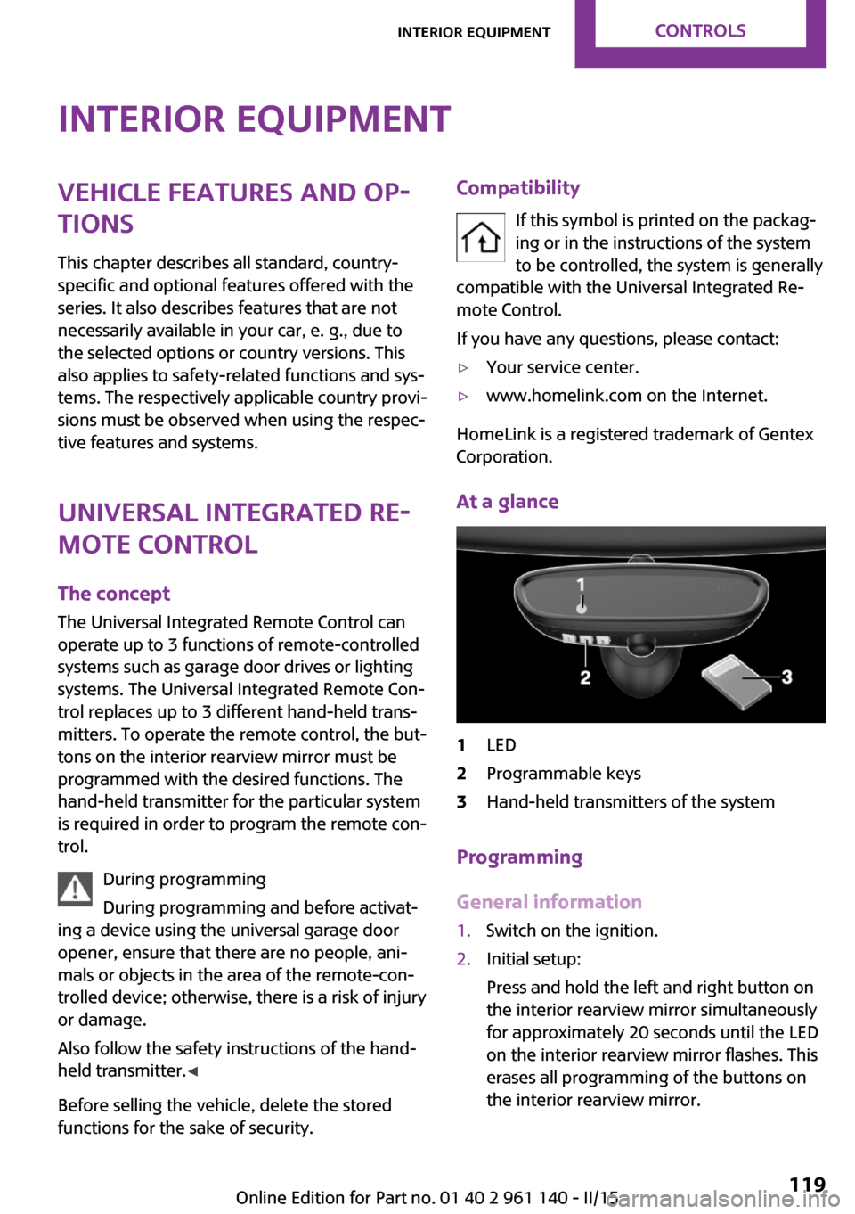
1LED2Programmable keys3Hand-held transmitters of the system
Programming
General information
1.Switch on the ignition.2.Initial setup:
Press and hold the left and right button on
the interior rearview mirror simultaneously
for approximately 20 seconds until the LED
on the interior rearview mirror flashes. This
erases all programming of the buttons on
the interior rearview mirror.Seite 119Interior equipmentCONTROLS119
Online Edition for Part no. 01 40 2 961 140 - II/15
Page 124 of 251
3.Hold the hand-held transmitter for the sys‐
tem to be controlled approx. 1 to 3 in/2.5
to 8 cm away from the buttons of the inte‐
rior rearview mirror. The required distance
depends on the manual transmitter.4.Simultaneously press and hold the button
of the desired function on the hand-held
transmitter and the button to be program‐
med on the interior rearview mirror. The
LED on the interior rearview mirror will be‐
gin flashing slowly.5.Release both buttons as soon as the LED
flashes more rapidly. The LED flashing
faster indicates that the button on the inte‐
rior rearview mirror has been programmed.
If the LED does not flash faster after at least
60 seconds, change the distance between
the interior rearview mirror and the hand-
held transmitter and repeat the step. Sev‐
eral more attempts at different distances
may be necessary. Wait at least 15 seconds
between attempts.
Canada: if programming with the hand-
held transmitter was interrupted, hold
down the interior rearview mirror button
and repeatedly press and release the hand-
held transmitter button for 2 seconds.6.To program other functions on other but‐
tons, repeat steps 3 to 5.
The systems can be controlled using the interior
rearview mirror buttons.
Special feature of the alternating-code
wireless system
If you are unable to operate the system after
repeated programming, please check if the sys‐
tem to be controlled features an alternating-
code system.
Read the system's operating manual, or press
the programmed button on the interior rear‐
view mirror longer. If the LED on the interior
rearview mirror starts flashing rapidly and then
stays lit constantly for 2 seconds, the system
features an alternating-code system. Flashing
and continuous illumination of the LED will re‐
peat for approximately 20 seconds.
For systems with an alternating-code system,
the Universal Integrated Remote Control and
the system also have to be synchronized.
Please read the operating manual to find out
how to synchronize the system.
Synchronizing is easier with the aid of a second
person.
To synchronize:1.Park the vehicle within range of the re‐
mote-controlled system.2.Program the relevant button on the interior
rearview mirror as described.3.Locate and press the synchronizing button
on the system being programmed. You
have approx. 30 seconds for the next step.4.Hold down the programmed button on the
interior rearview mirror for approximately
3 seconds and then release it. If necessary,
repeat this step up to three times in order
to finish synchronization. Once synchroni‐
zation is complete, the programmed func‐
tion will be carried out.
Reprogramming individual buttons
1.Switch on the ignition.2.Press and hold the interior rearview mirror
button to be programmed.3.As soon as the interior rearview mirror LED
starts flashing slowly, hold the hand-held
transmitter for the system to be controlled
approx. 1 to 3 in/2.5 to 8 cm away from the
buttons of the interior rearview mirror. The
required distance depends on the manual
transmitter.4.Likewise, press and hold the button of the
desired function on the hand-held trans‐
mitter.5.Release both buttons as soon as the interior
rearview mirror LED flashes more rapidly.
The LED flashing faster indicates that theSeite 120CONTROLSInterior equipment120
Online Edition for Part no. 01 40 2 961 140 - II/15
Page 125 of 251
button on the interior rearview mirror has
been programmed. The system can then be
controlled by the button on the interior
rearview mirror.
If the LED does not flash faster after at least
60 seconds, change the distance and re‐
peat the step. Several more attempts at dif‐
ferent distances may be necessary. Wait at
least 15 seconds between attempts.
Canada: if programming with the hand-
held transmitter was interrupted, hold
down the interior rearview mirror button
and repeatedly press and release the hand-
held transmitter button for 2 seconds.
Controls
Before operation
Before operating a system using the uni‐
versal garage door opener, ensure that there
are no people, animals, or objects within the
range of movement of the remote-controlled
system; otherwise, there is a risk of injury or
damage.
Also follow the safety instructions of the hand-
held transmitter. ◀
The system, such as the garage door, can be
operated using the button on the interior rear‐
view mirror while the engine is running or
when the ignition is started. To do this, hold
down the button within receiving range of the
system until the function is activated. The inte‐
rior rearview mirror LED stays lit while the wire‐
less signal is being transmitted.
Deleting stored functions
Press and hold the left and right button on the
interior rearview mirror simultaneously for ap‐
proximately 20 seconds until the LED flashes
rapidly. All stored functions are deleted. The
functions cannot be deleted individually.
Digital compass
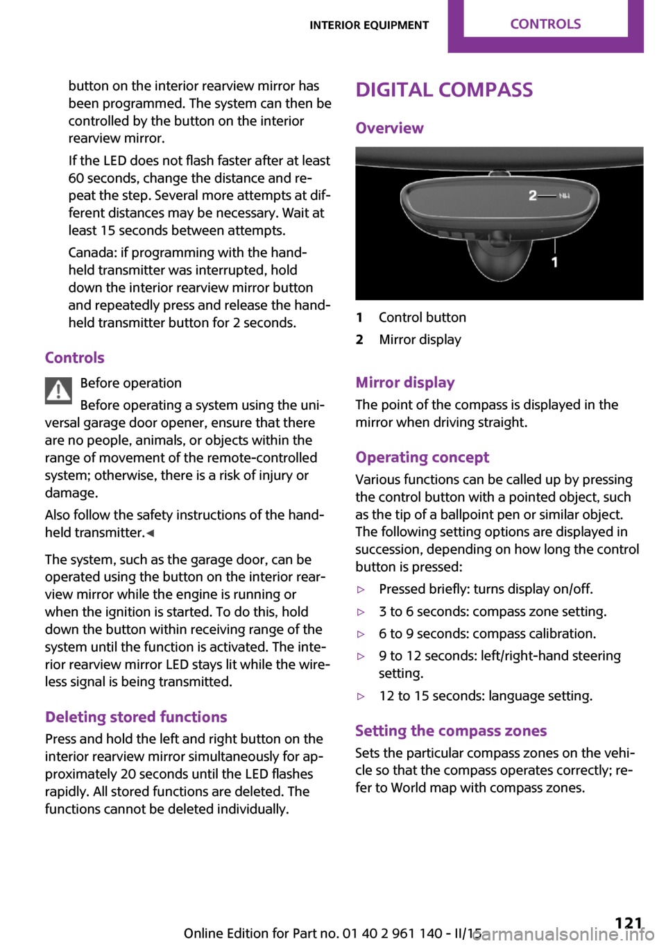
Overview1Control button2Mirror display
Mirror displayThe point of the compass is displayed in the
mirror when driving straight.
Operating concept Various functions can be called up by pressing
the control button with a pointed object, such
as the tip of a ballpoint pen or similar object.
The following setting options are displayed in
succession, depending on how long the control
button is pressed:
▷Pressed briefly: turns display on/off.▷3 to 6 seconds: compass zone setting.▷6 to 9 seconds: compass calibration.▷9 to 12 seconds: left/right-hand steering
setting.▷12 to 15 seconds: language setting.
Setting the compass zones
Sets the particular compass zones on the vehi‐
cle so that the compass operates correctly; re‐
fer to World map with compass zones.
Seite 121Interior equipmentCONTROLS121
Online Edition for Part no. 01 40 2 961 140 - II/15
Page 127 of 251

Settings are stored automatically after approxi‐
mately 10 seconds.
Sun visor
Glare shield
Fold the sun visor down or up.
Vanity mirror
A vanity mirror is located in the sun visor be‐
hind a cover. When the cover is opened, the
mirror lighting switches on.
Ashtray/cigarette
lighter
At a glance
The ashtray is located in one of the frontal cup
holders, the cigarette lighter above it in the
center console.
Ashtray In order to empty the ashtray, remove the ash‐
tray from the cupholder.
Lighter Danger of burns
Only hold the hot lighter by its knob; oth‐
erwise, there is a danger of getting burned.
Switch off the ignition and take the remote
control with you when leaving the vehicle so
that children cannot use the lighter and burn
themselves. ◀
Replace the cover after use
Reinsert the lighter or socket cover after
use, otherwise objects may get into the lighter
socket or fixture and cause a short circuit. ◀
Push in the lighter.
The lighter can be removed as
soon as it pops back out.
Connecting electrical de‐ vices
Hints Do not connect charging devices to the
12 volt socket in the vehicle
Do not connect battery chargers to the factory-
installed 12 volt sockets in the vehicle as this
may damage the vehicle battery due to an in‐
creased power consumption. ◀
Replace the cover after use
Reinsert the lighter or socket cover after
use, otherwise objects may get into the lighter
socket or fixture and cause a short circuit. ◀
Keep the airbag unfolding area clear
Make sure that the devices and cable are
located outside of the airbag's unfolding area;
otherwise, its unfolding can be hampered or
objects can be hurled through the interior
when the airbag unfolds. ◀
Sockets Sockets can be used for the running electrical
devices with the engine running or with the ig‐Seite 123Interior equipmentCONTROLS123
Online Edition for Part no. 01 40 2 961 140 - II/15
Page 153 of 251
RadioVehicle features and op‐
tions
This chapter describes all standard, country-
specific and optional features offered with the
series. It also describes features that are not
necessarily available in your car, e. g., due to
the selected options or country versions. This
also applies to safety-related functions and sys‐
tems. The respectively applicable country provi‐
sions must be observed when using the respec‐
tive features and systems.
General information Settings are stored for the profile, refer to
page 23, currently in use.
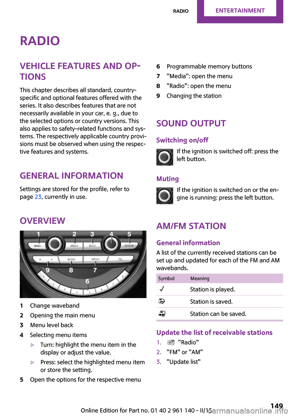
Overview1Change waveband2Opening the main menu3Menu level back4Selecting menu items▷Turn: highlight the menu item in the
display or adjust the value.▷Press: select the highlighted menu item
or store the setting.5Open the options for the respective menu6Programmable memory buttons7"Media": open the menu8"Radio": open the menu9Changing the station
Sound output
Switching on/off If the ignition is switched off: press the
left button.
Muting If the ignition is switched on or the en‐
gine is running: press the left button.
AM/FM station General information
A list of the currently received stations can be
set up and updated for each of the FM and AM
wavebands.
SymbolMeaningStation is played.Station is saved.Station can be saved.
Update the list of receivable stations
1. "Radio"2."FM" or "AM"3."Update list"Seite 149RadioENTERTAINMENT149
Online Edition for Part no. 01 40 2 961 140 - II/15
Page 166 of 251
Bluetooth hands-free systemVehicle features and op‐
tions
This chapter describes all standard, country-
specific and optional features offered with the
series. It also describes features that are not
necessarily available in your car, e. g., due to
the selected options or country versions. This
also applies to safety-related functions and sys‐
tems. The respectively applicable country provi‐
sions must be observed when using the respec‐
tive features and systems.
The concept Mobile phones can be connected to the vehicle
via Bluetooth. After the mobile phones are
paired once, they are recognized automatically
when the ignition is switched on. As soon as
they are inside the vehicle they can be oper‐
ated via the radio and via the buttons on the
steering wheel.
Hints Using the mobile phone while driving
Make entries only when traffic and road
conditions allow. Do not hold the mobile phone
in your hand while you are driving; use the
hands-free system instead. If you do not ob‐
serve this precaution, you can endanger the ve‐
hicle's occupants and other traffic. ◀
Certain functions may need to be enabled by the mobile phone provider or service provider.
At high temperatures, the charge functions of
the mobile phone can be limited under certain
circumstances, and some functions are no lon‐
ger executed.Do not operate a mobile phone that is con‐
nected to the vehicle on the mobile phone key‐
pad, as this may lead to a malfunction.
When the mobile phone is used via the vehicle,
refer to the operating manual of the mobile
phone.
Approved mobile phones Accurate information about which mobile
phones are supported with a Bluetooth inter‐
face is available at www.mini.com/connectivity.
These approved mobile phones, with a certain
software version, support the vehicle functions
described below.
Malfunctions may occur with other mobile
phones or software versions.
Displaying the vehicle identification
number and software part number
The vehicle identification number and software
part number are needed to determine which
mobile phones are supported by the mobile
phone installation package. The software ver‐
sion of the mobile phone may also be required.1. "Telephone"2. Press button.3."Bluetooth® info"4."System information"
Pairing/unpairing the
mobile phone
Requirements
▷The mobile phone is compatible.▷The mobile phone is ready for operation.Seite 162COMMUNICATIONBluetooth hands-free system162
Online Edition for Part no. 01 40 2 961 140 - II/15
Page 167 of 251
▷The ignition is switched on.▷Bluetooth connection on the vehicle and on
the mobile phone activated.▷Bluetooth presets may need to be made on
the mobile phone, e.g., for a connection
without confirmation or visibility, refer to
the mobile phone operating instructions.▷Set Bluetooth passkey for one-time use in
the logon procedure.▷Vehicle is stationary.
Bluetooth activation/deactivation
1. "Telephone"2. Press button.3."Bluetooth®"
Pairing and connecting
Pairing the mobile phone
To avoid becoming distracted and posing
an unnecessary hazard both to your own vehi‐
cle's occupants and to other traffic, only pair
the mobile phone while the vehicle is station‐
ary. ◀
1. "Telephone"2.A mobile phone has not yet been paired:
"OK"
A mobile phone has been paired:
"Bluetooth®"3.A mobile phone has not yet been paired:
the Bluetooth name of the vehicle is shown
on the display.
A mobile phone has not yet been paired:
"Add new phone". The Bluetooth name of
the vehicle is shown on the display.4.To perform additional steps on the mobile
phone, refer to the mobile phone operating
instructions.The Bluetooth name of the vehicle appears
on the mobile phone display. Select this.5.Enter the same passkey on the mobile
phone and on the display
Or
Compare the control number on the display
with the control number in the display of
the mobile phone and confirm.
Four mobile phones can be logged in on the
vehicle, and one mobile phone can be con‐
nected to the vehicle.
Following the initial pairing Mobile phone is connected to the vehicle after
a brief time.
The phone book entries stored on the SIM card
or in the mobile phone are transferred to the
vehicle.
Specific settings may be necessary in some mo‐
bile phones, e.g., authorization or a secure con‐
nection; refer to the mobile phone operating
instructions.
Connecting a particular mobile phone
1. "Telephone"2."Bluetooth®"3.Select the mobile phone that is to be con‐
nected.
Unpairing the mobile phone
1. "Telephone"2."Bluetooth®"3.Highlight any mobile phone that is to be re‐
moved.4. Press button.5."Remove device" or "Remove all devices"
What to do if...
Information on suitable mobile phones, refer to
page 162.
Seite 163Bluetooth hands-free systemCOMMUNICATION163
Online Edition for Part no. 01 40 2 961 140 - II/15