fuel MINI Hardtop 2 Door 2015 Owner's Manual
[x] Cancel search | Manufacturer: MINI, Model Year: 2015, Model line: Hardtop 2 Door, Model: MINI Hardtop 2 Door 2015Pages: 251, PDF Size: 11.4 MB
Page 9 of 251

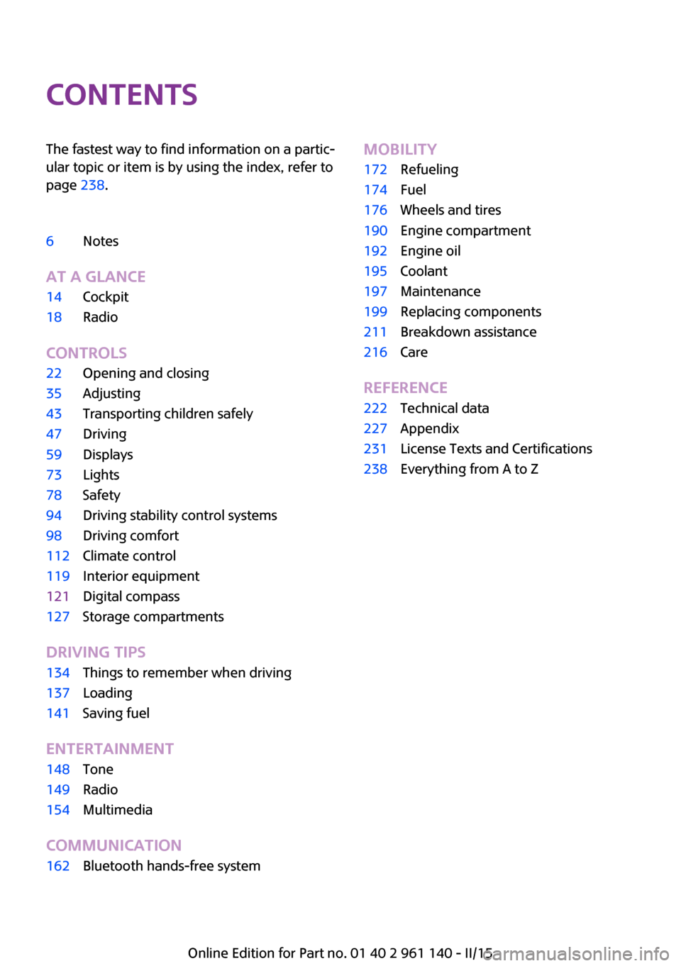
ContentsThe fastest way to find information on a partic‐
ular topic or item is by using the index, refer to
page 238.6Notes
AT A GLANCE
14Cockpit18Radio
CONTROLS
22Opening and closing35Adjusting43Transporting children safely47Driving59Displays73Lights78Safety94Driving stability control systems98Driving comfort112Climate control119Interior equipment121Digital compass127Storage compartments
DRIVING TIPS
134Things to remember when driving137Loading141Saving fuel
ENTERTAINMENT
148Tone149Radio154Multimedia
COMMUNICATION
162Bluetooth hands-free systemMOBILITY172Refueling174Fuel176Wheels and tires190Engine compartment192Engine oil195Coolant197Maintenance199Replacing components211Breakdown assistance216Care
REFERENCE
222Technical data227Appendix231License Texts and Certifications238Everything from A to Z
Online Edition for Part no. 01 40 2 961 140 - II/15
Page 30 of 251

This device complies with part 15 of the FCC
Rules. Operation is subject to the following two
conditions:▷This device may not cause harmful interfer‐
ence, and▷this device must accept any interference re‐
ceived, including interference that may
cause undesired operation.
Any unauthorized modifications or changes to
these devices could void the user's authority to
operate this equipment.
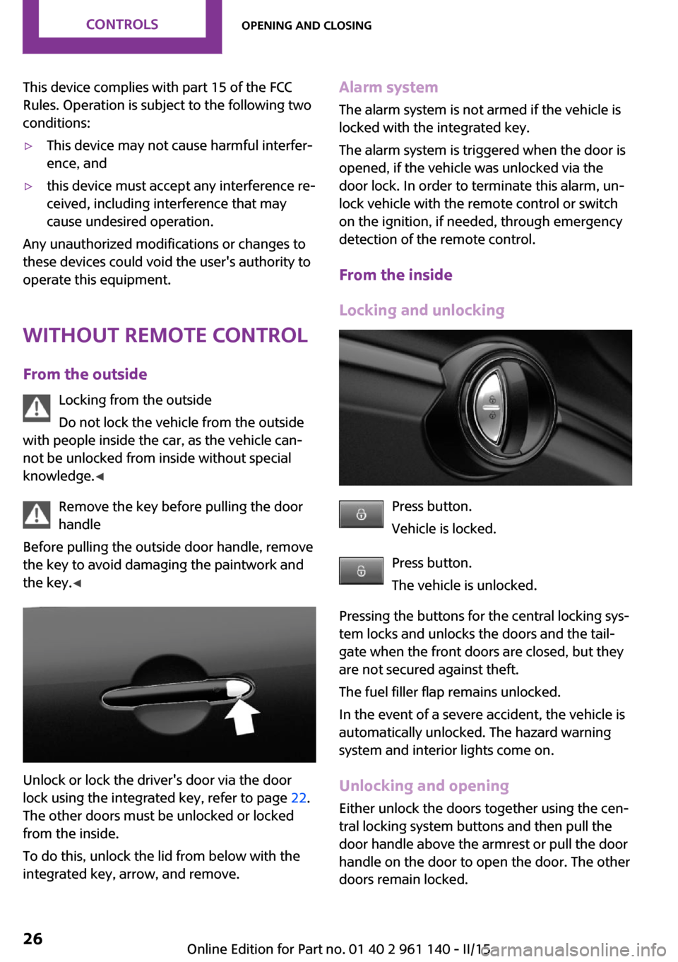
Without remote control From the outside Locking from the outside
Do not lock the vehicle from the outside
with people inside the car, as the vehicle can‐
not be unlocked from inside without special
knowledge. ◀
Remove the key before pulling the door
handle
Before pulling the outside door handle, remove
the key to avoid damaging the paintwork and
the key. ◀
Unlock or lock the driver's door via the door
lock using the integrated key, refer to page 22.
The other doors must be unlocked or locked
from the inside.
To do this, unlock the lid from below with the
integrated key, arrow, and remove.
Alarm system
The alarm system is not armed if the vehicle is
locked with the integrated key.
The alarm system is triggered when the door is
opened, if the vehicle was unlocked via the
door lock. In order to terminate this alarm, un‐
lock vehicle with the remote control or switch
on the ignition, if needed, through emergency
detection of the remote control.
From the inside
Locking and unlocking
Press button.
Vehicle is locked.
Press button.
The vehicle is unlocked.
Pressing the buttons for the central locking sys‐
tem locks and unlocks the doors and the tail‐
gate when the front doors are closed, but they
are not secured against theft.
The fuel filler flap remains unlocked.
In the event of a severe accident, the vehicle is
automatically unlocked. The hazard warning
system and interior lights come on.
Unlocking and opening
Either unlock the doors together using the cen‐
tral locking system buttons and then pull the
door handle above the armrest or pull the door
handle on the door to open the door. The other
doors remain locked.
Seite 26CONTROLSOpening and closing26
Online Edition for Part no. 01 40 2 961 140 - II/15
Page 33 of 251

▷Interference of the radio connection from
transmission towers or other equipment
with high transmit power.▷Shielding of the remote control due to
metal objects.▷Interference of the radio connection from
mobile phones or other electronic devices
in direct proximity.
Do not transport the remote control together
with metal objects or electronic devices.
In the case of a malfunction, unlock and lock
the vehicle using the buttons of the remote
control or using the integrated key, refer to
page 26.
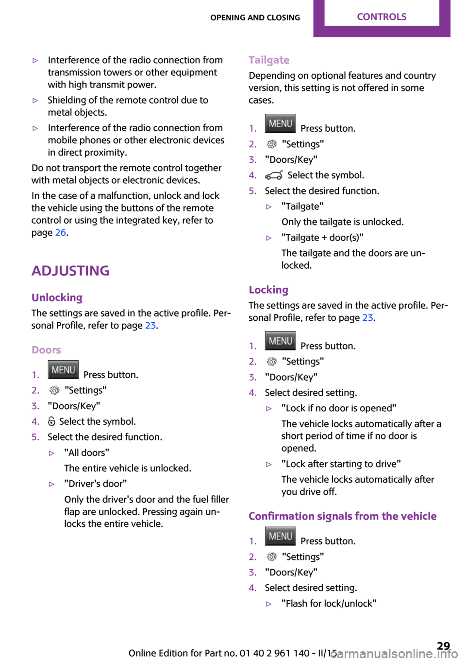
Adjusting Unlocking The settings are saved in the active profile. Per‐
sonal Profile, refer to page 23.
Doors
1. Press button.2. "Settings"3."Doors/Key"4. Select the symbol.5.Select the desired function.▷"All doors"
The entire vehicle is unlocked.▷"Driver's door"
Only the driver's door and the fuel filler
flap are unlocked. Pressing again un‐
locks the entire vehicle.Tailgate
Depending on optional features and country
version, this setting is not offered in some
cases.1. Press button.2. "Settings"3."Doors/Key"4. Select the symbol.5.Select the desired function.▷"Tailgate"
Only the tailgate is unlocked.▷"Tailgate + door(s)"
The tailgate and the doors are un‐
locked.
Locking
The settings are saved in the active profile. Per‐
sonal Profile, refer to page 23.
1. Press button.2. "Settings"3."Doors/Key"4.Select desired setting.▷"Lock if no door is opened"
The vehicle locks automatically after a
short period of time if no door is
opened.▷"Lock after starting to drive"
The vehicle locks automatically after
you drive off.
Confirmation signals from the vehicle
1. Press button.2. "Settings"3."Doors/Key"4.Select desired setting.▷"Flash for lock/unlock"Seite 29Opening and closingCONTROLS29
Online Edition for Part no. 01 40 2 961 140 - II/15
Page 52 of 251

▷After approx. 8 minutes.▷When the vehicle is locked using the central
locking system.▷Shortly before the battery is discharged
completely, so that the engine can still be
started.
The radio-ready state remains active if, e.g., the
ignition is automatically switched off for the fol‐
lowing reasons:
▷Opening or closing the driver's door.▷Unfastening of the driver's safety belt.▷When automatically switching from low
beams to parking lights.
If the engine is switched off and the ignition is
switched on, the system automatically switches
to the radio-ready state if the lights are turned
off or, if correspondingly equipped, the day‐
time running lights are activated.
Starting the engine
Hints Enclosed areas
Do not let the engine run in enclosed
areas, since breathing in exhaust fumes may
lead to loss of consciousness and death. The
exhaust gases contain carbon monoxide, an
odorless and colorless but highly toxic gas. ◀
Unattended vehicle
Do not leave the vehicle unattended with
the engine running; doing so poses a risk of
danger.
Before leaving the vehicle with the engine run‐
ning, set the parking brake and place the trans‐
mission in selector lever position P or N to pre‐
vent the vehicle from moving. ◀
Repeated starting in quick succession
Avoid trying to start the vehicle repeat‐
edly and in quick succession. Otherwise, the
fuel is not burned or is inadequately burned,
posing a risk of overheating and damage to the
catalytic converter. ◀
Do not wait for the engine to warm-up while
the vehicle remains stationary. Start driving at
moderate engine speeds.
Steptronic transmission
Starting the engine1.Depress the brake pedal.2.Engage selector lever position P or N.3.Press the Start/Stop button.
The ignition is activated automatically for a cer‐
tain time and is stopped as soon as the engine
starts.
Manual transmission
Starting the engine
1.Depress the brake pedal.2.Press on the clutch pedal and shift to neu‐
tral.3.Press the Start/Stop button.
The ignition is activated automatically for a cer‐
tain time and is stopped as soon as the engine
starts.
Engine stop
Hints Take the remote control with you
Take the remote control with you when
leaving the vehicle so that children, e.g., cannot
start the engine. ◀
Apply parking brake and further secure
the vehicle if needed.
Set the parking brake firmly when parking; oth‐
erwise, the vehicle could roll. On steep upward
and downward inclines, further secure the ve‐
Seite 48CONTROLSDriving48
Online Edition for Part no. 01 40 2 961 140 - II/15
Page 53 of 251

hicle, e.g., by turning the steering wheel in the
direction of the curb. ◀
Before driving into a car wash So that the vehicle can roll into a car wash ob‐
serve instructions for going into an automatic
car wash, refer to page 216.
Steptronic transmission
Switching off the engine1.Engage selector lever position P with the
vehicle stopped.2.Press the Start/Stop button.
The engine is switched off.
The radio-ready state is switched on.3.Set the parking brake.
Manual transmission
Switching off the engine
1.With the vehicle at a standstill, press the
Start/Stop button.
The engine is switched off.
The radio-ready state is switched on.2.Shift into first gear or reverse.3.Set the parking brake.
Auto Start/Stop function
The concept
The Auto Start/Stop function helps save fuel.
The system switches off the engine during a
stop, e.g., in traffic congestion or at traffic
lights. The ignition remains switched on. The
engine starts again automatically for driving off.
Automatic operation
After every start of the engine using the Start/
Stop button, the Auto Start/Stop function is in
the last selected state, refer to page 50. When
the Auto Start/Stop function is active, it is avail‐
able when the vehicle is traveling faster than
about 3 mph, approx. 5 km/h.
Engine stop
The engine is switched off automatically during
a stop under the following conditions:
Manual transmission:▷Neutral is engaged and the clutch pedal is
not pressed.▷The driver's safety belt is buckled or the
driver's door is closed.
Steptronic transmission:
▷The selector lever is in selector lever posi‐
tion D.▷Brake pedal remains depressed while the
vehicle is stopped.▷The driver's safety belt is buckled or the
driver's door is closed.
In order to be able to release the brake pedal,
engage lever in position P. The engine remains
off.
To continue driving depress the brake pedal.
When a gear is engaged, the engine starts au‐
tomatically.
The air flow from the air conditioner is reduced
when the engine is switched off.
Displays in the instrument cluster The display indicates that theAuto Start/Stop function is ready
for an Automatic engine start.
The display indicates that the
conditions for an automatic en‐
gine stop have not been met.
Seite 49DrivingCONTROLS49
Online Edition for Part no. 01 40 2 961 140 - II/15
Page 63 of 251

DisplaysVehicle features and op‐tions
This chapter describes all standard, country-
specific and optional features offered with the
series. It also describes features that are notnecessarily available in your car, e. g., due to
the selected options or country versions. This
also applies to safety-related functions and sys‐
tems. The respectively applicable country provi‐
sions must be observed when using the respec‐
tive features and systems.
Instrument cluster
Overview, instrument cluster
1Tachometer 642Messages, e.g. Check Control3Speedometer4Fuel gauge 645Display/reset miles 646Electronic displays 60Seite 59DisplaysCONTROLS59
Online Edition for Part no. 01 40 2 961 140 - II/15
Page 68 of 251

Fuel gaugeVehicle tilt position may cause
the display to vary.
The arrow beside the fuel pump
symbol shows which side of the
vehicle the fuel filler flap is on.
Notes on refueling, refer to page 172.
Tachometer
Always avoid engine speeds in the red warning
field. In this range, the fuel supply is interrupted
to protect the engine.
Odometer and trip odom‐
eter
The concept
Odometer and trip odometer are displayed in
the instrument cluster.
Resetting the trip odometer Press the knob.▷The odometer is displayed
when the ignition is switched
off.▷When the ignition is switched
on, the trip odometer is re‐
set.
External temperature
If the indicator drops to
+37 ℉/+3 ℃, a signal sounds.
A Check Control message is dis‐
played.
There is an increased risk of ice
on roads.
Ice on roads
Even at temperatures above
+37 ℉/+3 ℃, roads might be icy.
Therefore, drive carefully on bridges and
shaded roads, e.g., to avoid the increased risk
of an accident. ◀
Time The time is displayed in the in‐
strument cluster.
Setting the time on the radio, re‐
fer to page 69.
Date The date is displayed in the in‐
strument cluster.
Set the date on the radio, refer
to page 69.
Range Display With a low remaining range:▷A Check Control message is
displayed briefly.▷The remaining range is
shown on the computer.▷With a dynamic driving style - e.g., taking
curves aggressively - engine operation
might vary.
The Check Control message appears continu‐
ously below a range of approx. 30 miles/50 km.
Refuel promptly
Refuel no later than at a range of
30 miles/50 km or engine operation might fail
and damage might occur. ◀
Seite 64CONTROLSDisplays64
Online Edition for Part no. 01 40 2 961 140 - II/15
Page 69 of 251

Displaying the cruising range1. Press button.2. "Settings"3."Instrument cluster display"4."Range"
Current fuel consump‐
tion
The concept
Displays the current fuel consumption. Check
whether you are currently driving in an efficient
and environmentally-friendly manner.
Service requirements
The concept
After the ignition is turned on the instrument
cluster briefly displays available driving distance
or time to the next scheduled maintenance.
Your service specialist can read the current
service requirements from your remote control.
Display
Detailed information on service
requirements
The radio will display detailed information
about service requirements.
1. Press button.2. "Vehicle Info"3."Vehicle status"4."Service required"5.Select the desired entry to view detailed in‐
formation.SymbolsSymbolsDescriptionNo service is currently required.The deadline for scheduled
maintenance or a legally man‐
dated inspection is approach‐
ing.The service deadline has al‐
ready passed.
Entering appointment dates
Enter the dates for the required inspections.
Make sure that the vehicle's date and time are
set correctly.
1. Press button.2. "Vehicle Info"3."Vehicle status"4."Service required"5."§ Vehicle inspection" or"§ Emission
inspection"6."Change date"7.Enter the desired appointment.
Gear shift indicator
The concept
The system recommends the most fuel efficient
gear for the current driving situation.
Depending on the vehicle's features and coun‐
try version of the vehicle, the gear shift indica‐
tor is active in the manual mode of the Step‐
tronic transmission and with manual
transmission.
Suggestions to shift gear up or down are dis‐
played in the instrument cluster.
Seite 65DisplaysCONTROLS65
Online Edition for Part no. 01 40 2 961 140 - II/15
Page 70 of 251

Manual transmission: displayingExampleDescriptionFuel efficient gear is set.Shift into fuel efficient gear.
Steptronic transmission: Displaying
ExampleDescriptionFuel efficient gear is set.Shift into fuel efficient gear.
Speed limit detection
The concept
Speed limit detection
Speed limit detection uses a symbol in the
shape of a traffic sign to display the currently
detected speed limit. The camera at the base of
the interior rearview mirror detects traffic signs
at the edge of the road as well as variable over‐
head sign posts. Traffic signs with extra symbols
for wet road conditions, etc. are also detected
and compared with the vehicle's onboard data,
such as for the rain sensor, and will be dis‐
played depending on the situation.
Without a navigation system, the system is sub‐
ject to limitations imposed by technology.
Speed limits with extra text characters are al‐
ways displayed.
Hints
Speed limits when towing a trailer are not
shown.
Personal judgment
The system cannot serve as a substitute
for the driver's personal judgment of the traffic
situation.
The system assists the driver and does not re‐
place the human eye. ◀
At a glance
Camera
The camera is found near the interior rearview
mirror.
Keep the windshield in the area behind the in‐
terior rearview mirror clean and clear.
Switching on/off
1. Press button.2. "Settings"3."Instrument cluster display"4."Speed limit information"
If speed limit detection is switched on, it can be
displayed on the info display in the instrument
cluster via the computer.
Display The following is displayed in the instrumentcluster:
Seite 66CONTROLSDisplays66
Online Edition for Part no. 01 40 2 961 140 - II/15
Page 72 of 251

Calling up information in the radioInformation is also shown on the radio display.1. Press button.2. "Vehicle Info"3."Onboard info"
Resetting values
1.Select the desired value.2."Reset?"
Information at a glance
Info display Repeatedly pressing the button
on the turn signal lever calls up the following information in the
info display:
▷Range.▷GREEN Info.
When GREEN Mode is activated.▷Average fuel consumption.▷Current fuel consumption.▷Average speed.▷Date.▷Engine temperature display.▷Speed limit detection.▷Speed.
Radio
Selected information is shown on the radio.
▷Range.▷Average fuel consumption.▷Average speed.Adjusting the info display
You can select what information from the com‐
puter is to be displayed on the info display of
the instrument cluster.1. Press button.2. "Settings"3."Instrument cluster display"4.Select the desired displays.
Information in detail
Range
Displays the estimated cruising range available
with the remaining fuel.
It is calculated based on your driving style over
the last 20 miles/30 km.
GREEN info Description of GREEN info, refer to page 143.
Average fuel consumption
This is calculated for the period while the en‐
gine is running.
The average fuel consumption is calculated for
the distance traveled since the last reset by the
on-board comupter.
Average speed
Periods in which the vehicle is parked with the
engine manually stopped are not included in
the calculation of the average speed.
Resetting average valuesPress and hold the onboard computer button
on the turn signal lever.
Engine temperature display Displays the current engine temperature, based
on a combination of coolant and motor oil tem‐
perature. As soon as the optimum operating
temperature has been attained, the indicator is
in the center position.
Seite 68CONTROLSDisplays68
Online Edition for Part no. 01 40 2 961 140 - II/15