turn signal MINI Hardtop 4 Door 2016 (Mini Connected) User Guide
[x] Cancel search | Manufacturer: MINI, Model Year: 2016, Model line: Hardtop 4 Door, Model: MINI Hardtop 4 Door 2016Pages: 246, PDF Size: 6.36 MB
Page 145 of 246

4.Likewise, press and hold the button of the
desired function on the hand-held trans‐
mitter.5.Release both buttons as soon as the interior
rearview mirror LED flashes more rapidly.
The LED flashing faster indicates that the
button on the interior rearview mirror has
been programmed. The system can then be
controlled by the button on the interior
rearview mirror.
If the LED does not flash faster after at least
60 seconds, change the distance and re‐
peat the step. Several more attempts at dif‐
ferent distances may be necessary. Wait at
least 15 seconds between attempts.
Canada: if programming with the hand-
held transmitter was interrupted, hold
down the interior rearview mirror button
and repeatedly press and release the hand-
held transmitter button for 2 seconds.
Controls
WARNING
Body parts can be jammed when operat‐
ing remote-controlled systems, e.g. the garage
door, using the universal garage door opener.
There is risk of injuries or risk of property dam‐
age. Make sure that the area of movement of
the respective system is clear during program‐
ming and operation. Also follow the safety in‐
structions of the hand-held transmitter. ◀
The system, such as the garage door, can be
operated using the button on the interior rear‐
view mirror while the engine is running or
when the ignition is started. To do this, hold
down the button within receiving range of the
system until the function is activated. The inte‐
rior rearview mirror LED stays lit while the wire‐
less signal is being transmitted.
Deleting stored functions
Press and hold the left and right button on the
interior rearview mirror simultaneously for ap‐
proximately 20 seconds until the LED flashes
rapidly. All stored functions are deleted. The
functions cannot be deleted individually.
Digital compass
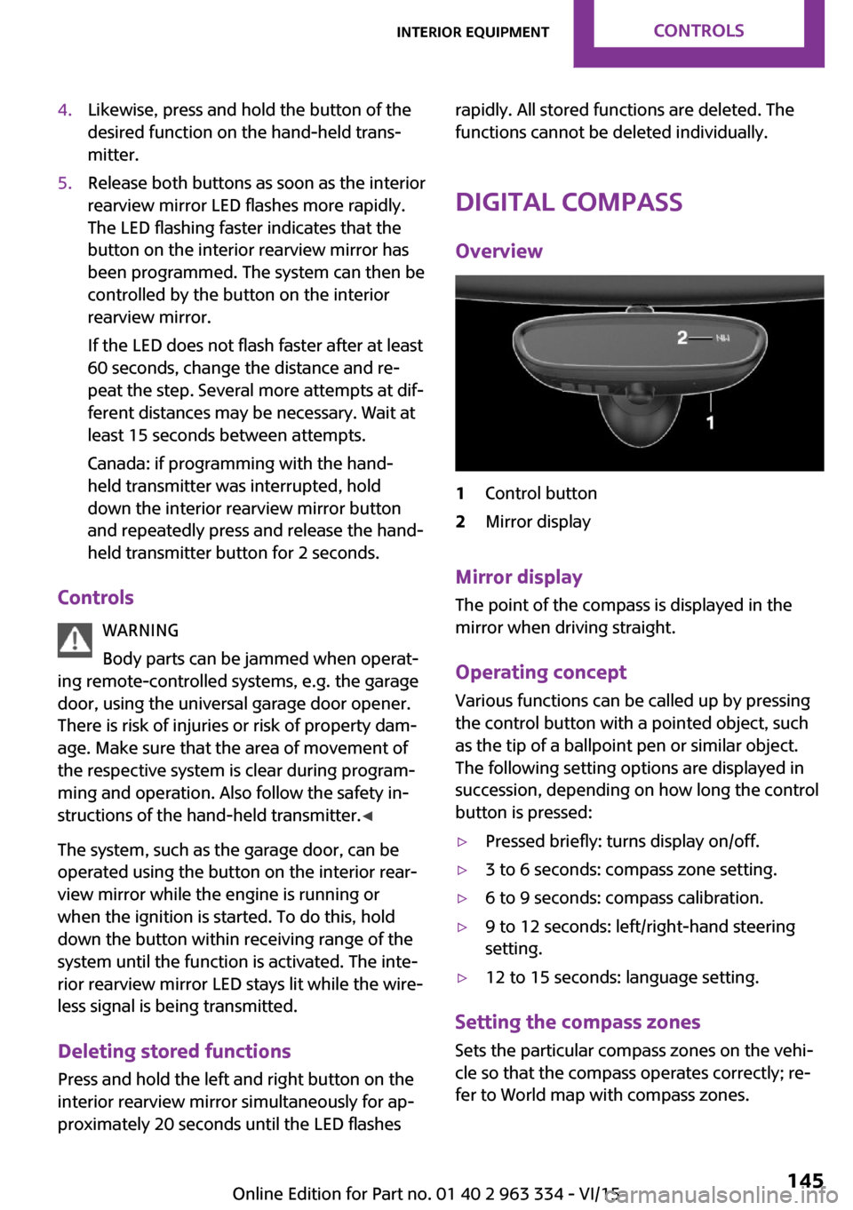
Overview1Control button2Mirror display
Mirror display The point of the compass is displayed in the
mirror when driving straight.
Operating concept Various functions can be called up by pressing
the control button with a pointed object, such
as the tip of a ballpoint pen or similar object.
The following setting options are displayed in
succession, depending on how long the control
button is pressed:
▷Pressed briefly: turns display on/off.▷3 to 6 seconds: compass zone setting.▷6 to 9 seconds: compass calibration.▷9 to 12 seconds: left/right-hand steering
setting.▷12 to 15 seconds: language setting.
Setting the compass zones
Sets the particular compass zones on the vehi‐
cle so that the compass operates correctly; re‐
fer to World map with compass zones.
Seite 145Interior equipmentCONTROLS145
Online Edition for Part no. 01 40 2 963 334 - VI/15
Page 163 of 246

Securing
Follow the installation instructions of the roof
rack.
Loading Because roof racks raise the vehicle's center of
gravity when loaded, they have a major effect
on vehicle handling and steering response.
Therefore, note the following when loading and
driving:▷Do not exceed the approved roof/axle
loads and the approved gross vehicle
weight.▷Be sure that adequate clearance is main‐
tained for tilting and opening the glass sun‐
roof.▷Distribute the roof load uniformly.▷The roof load should not extend past the
loading area.▷Always place the heaviest pieces on the
bottom.▷Secure the roof luggage firmly, e.g., tie with
ratchet straps.▷Do not let objects project into the opening
path of the tailgate.▷Drive cautiously and avoid sudden acceler‐
ation and braking maneuvers. Take corners
gently.
Rear luggage rack
General information Installation only possible with rear luggage rack
preparation.
Rear racks are available as special accessories.
Information Follow the installation instructions of the rear
luggage rack.
Drive cautiously and avoid sudden acceleration
and braking maneuvers. Take corners gently.
SecuringCOOPER/COOPER D/ONE/ONE DCOOPER S/COOPER SD
The anchorage points, arrow 1, and the socket,
arrow 2, are located below the covers in the
bumper.
Remove the covers before installing the rear
luggage rack.
Power consumption
Before starting to drive, check the function of
the tail lamps of the rear luggage rack.
The rear luggage rack lights must not consume
more than:
▷Turn signals: 42 watts per side.▷Rear lights: 50 watts per side.▷Brake lights: 84 watts in total.▷Rear fog lights: 42 watts in total.▷Backup lamp: 42 watts in total.Seite 163LoadingDRIVING TIPS163
Online Edition for Part no. 01 40 2 963 334 - VI/15
Page 204 of 246

Headlight glass
Condensation can form on the inside of the ex‐
ternal lights in cool or humid weather. When
driving with the lights switched on, the conden‐
sation evaporates after a short time. The head‐
light glass does not need to be changed.
If despite driving with the lights switched on,
increasing humidity forms, e. g. water droplets
in the lamp, the manufacturer of your vehicle
recommends having it checked by a dealer’s
service center or another qualified service cen‐
ter or repair shop.
Front lights, bulb replacement
Overview Halogen headlights1Low beams/high beams2Turn signalLED headlights1Daytime running lights2Low beams/high beams3Turn signal
Bug light
1Parking lights2Daytime running lights3Fog lights
LED bug light
1Parking lights2Fog lightsSeite 204MOBILITYReplacing components204
Online Edition for Part no. 01 40 2 963 334 - VI/15
Page 205 of 246

LED low beams/LED high beamsFollow the general instructions on lights and
bulbs, refer to page 203.
The lights feature LED technology. Contact a
dealer’s service center or another qualified
service center or repair shop in the event of a
malfunction.
Halogen low beams/halogen high
beams
Follow the general instructions on lights and
bulbs, refer to page 203.
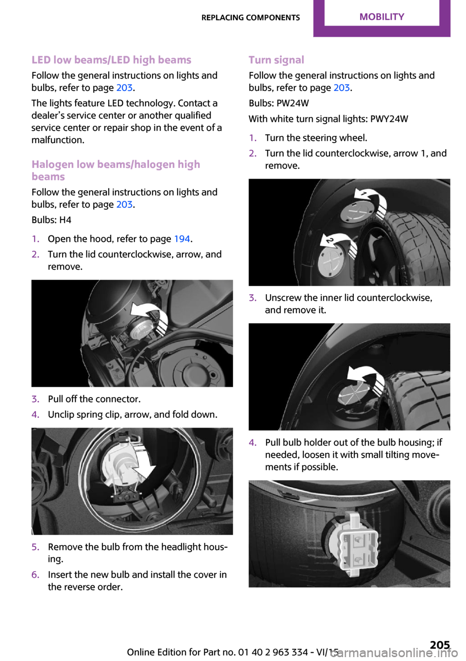
Bulbs: H41.Open the hood, refer to page 194.2.Turn the lid counterclockwise, arrow, and
remove.3.Pull off the connector.4.Unclip spring clip, arrow, and fold down.5.Remove the bulb from the headlight hous‐
ing.6.Insert the new bulb and install the cover in
the reverse order.Turn signal
Follow the general instructions on lights and
bulbs, refer to page 203.
Bulbs: PW24W
With white turn signal lights: PWY24W1.Turn the steering wheel.2.Turn the lid counterclockwise, arrow 1, and
remove.3.Unscrew the inner lid counterclockwise,
and remove it.4.Pull bulb holder out of the bulb housing; if
needed, loosen it with small tilting move‐
ments if possible.Seite 205Replacing componentsMOBILITY205
Online Edition for Part no. 01 40 2 963 334 - VI/15
Page 207 of 246

Vehicle with two rear fog lights1Side tail lights2Rear fog lights3License plate lamp4Center brake lamp
Side tail lights
1Brake lights/tail lights2Turn signal3Reversing lights
Side LED tail lights
1Tail lights2Turn signal3Brake light4Reversing lights
Side tail lights
Follow the general instructions on lights and
bulbs, refer to page 203.
Bulbs: P21W
1.Open tailgate, refer to page 40.2.Remove left or right cover.3.Through the opening, loosen the plug con‐
nector, arrow 2 on the bulb holder.
Press the latches together, arrows 1, and
remove the bulb holder.4.Remove the bulb holder from the opening.5.Press the nonworking bulb gently into the
socket, turn counterclockwise and remove.▷Arrow 1: brake lights/tail lights▷Arrow 2: turn signalSeite 207Replacing componentsMOBILITY207
Online Edition for Part no. 01 40 2 963 334 - VI/15
Page 209 of 246

The wire is long enough to guide the socket
down and through between any heat shield
that may be installed and the bumper.4.Replace nonworking bulb.5.To install the new bulb, proceed in reverse
order of removal.
Right fog lamp:
1.Turn the bulb socket counterclockwise and
remove.
The wire is long enough to guide the socket
down and through between any heat shield
that may be installed and the bumper.2.Replace nonworking bulb.3.To install the new bulb, proceed in reverse
order of removal.
Side turn signal, bulb replacement
Follow the general instructions on lights and
bulbs, refer to page 203.
Bulbs:
▷With orange lens: W5W▷With white lens: WY5W diadem1.Open the hood. The covers of the side turn
signal lights are on the left and right next to
the hinges of the hood.2.Loosen nuts of the cover by hand and re‐
move the cover.3.Turn the bulb holder counterclockwise and
remove.4.Replace the bulb.5.To insert the new bulb, proceed in reverse
order of removal. Insert the nuts of the
cover and press down.Seite 209Replacing componentsMOBILITY209
Online Edition for Part no. 01 40 2 963 334 - VI/15
Page 216 of 246

3.Let both engines run for several minutes.4.Disconnect the jumper cables in the reverse
order.
Check the battery and recharge if needed.
Tow-starting and towing
Information WARNING
Due to system limits, individual functions
can malfunction during tow-starting/towing
with the Intelligent Safety systems activated,
e.g. approach control warning with light brak‐
ing function. There is risk of an accident. Switch
all Intelligent Safety systems off prior to tow-
starting/towing. ◀
Switching off Intelligent Safety systems, refer to
page 108.
Steptronic transmission: transporting
your vehicle
Information Your vehicle must not be towed if the front
wheels are touching the ground.
CAUTION
The vehicle can be damaged when tow‐
ing the vehicle with a lifted rear axle. There is
risk of property damage. Have vehicle trans‐
ported only with lifted front axle or on a load‐
ing platform. ◀
Tow truck
Have your vehicle transported with a tow truck
with a so-called lift bar or on a flat bed.
CAUTION
When lifting the vehicle by the tow fitting
or body and chassis parts; damage can occur
on vehicle parts. There is risk of property dam‐
age. Lift vehicle using suitable means. ◀
Use tow fitting located in the front only for po‐
sitioning the vehicle.
Manual transmission
Observe before towing your vehicle
Gearshift lever in neutral position.
Towing CAUTION
If manual unlocking of the parking brake
is not possible, the vehicle cannot be moved or
towed. There is risk of property damage. The
vehicle should only be transported on a loading
platform. ◀
Information the following instructions:
▷Make sure that the ignition is switched on;
otherwise, the low beams, tail lights, turn
signals, and wipers may be unavailable.▷Do not tow the vehicle with the rear axle
tilted, as the front wheels could turn.▷When the engine is stopped, there is no
power assist. Consequently, more forceSeite 216MOBILITYBreakdown assistance216
Online Edition for Part no. 01 40 2 963 334 - VI/15
Page 237 of 246

Camera-based cruise con‐trol 119
Camera lenses, care 223
Camera, rearview cam‐ era 130
Can holder, see Cu‐ pholder 152
Car battery 212
Car care products 221
Care, displays 223
Care, vehicle 221
Cargo area 148
Cargo area, adapting size 153
Cargo area, enlarging 149
Cargo area lid 40
Cargo area, storage compart‐ ments 153
Cargo cover 148
Cargo, securing 162
Cargo straps, securing cargo 162
Car key, see Remote con‐ trol 34
Carpet, care 223
Car wash 220
Catalytic converter, see Hot exhaust system 159
CBS Condition Based Serv‐ ice 200
Center armrest 152
Center console 16
Central instrument cluster, LED ring 88
Central locking system 40
Central screen, refer to Control Display 18
Changes, technical, refer to Own Safety 7
Changing parts 202
Changing wheels 210
Changing wheels/tires 186
Chassis number, see vehicle identification number 10
Check Control 76
Checking the oil level elec‐ tronically 195 Children, seating position 58
Children, transporting safely 58
Child restraint fixing sys‐ tem 58
Child restraint fixing system LATCH 60
Child restraint fixing systems, mounting 59
Child safety locks 61
Child seat, mounting 59
Child seats 58
Chrome parts, care 222
Chrono package, cockpit 92
Cigarette lighter 147
Cleaning, displays 223
Climate control 136, 138
Clock 80
Closing/opening via door lock 39
Closing/opening with remote control 37
Clothes hooks 153
Coasting 168
Coasting with engine decou‐ pled, coasting 168
Coasting with idling en‐ gine 168
Combination switch, see Turn signals 67
Combi switch, see wiper sys‐ tem 68
Comfort Access 41
Compartments in the doors 152
Compass 145
Compressor 188
Condensation on win‐ dows 140
Condensation under the vehi‐ cle 160
Condition Based Service CBS 200
Configuring driving pro‐ gram 118
Confirmation signal 43 Control Display 18
Control Display, settings 87
Controller 19
Control systems, driving stabil‐ ity 115
Convenient opening 38
Coolant 198
Cooling function 137, 139
Cooling, maximum 139
Cooling system 198
Cornering lamp 96
Corrosion on brake discs 160
Cosmetic mirror 147
Courtesy lamps during unlock‐ ing 37
Courtesy lamps with the vehi‐ cle locked 38
Cruise control 124
Cruise control, active 119
Cruising range 81
Cupholder 152
Current fuel consumption 81
D
Damage, tires 186
Damping control, dy‐ namic 117
Data, technical 226
Date 80
Daytime running lights 96
Defrosting, refer to defrosting the windows 137
Defrosting, see Windows, de‐ frosting 140
Defrosting the windows 137
Dehumidifying, air 137, 139
Deleting personal data 24
Deletion of personal data 24
Destination distance 85
Digital clock 80
Digital compass 145
Dimensions 226
Dimmable exterior mirrors 56
Dimmable interior rearview mirror 56 Seite 237Everything from A to ZREFERENCE237
Online Edition for Part no. 01 40 2 963 334 - VI/15
Page 238 of 246

Direction indicator, see Turnsignals 67
Display, electronic, instrument cluster 76
Display, engine tempera‐ ture 85
Display lighting, see Instru‐ ment lighting 97
Displays 75
Displays, cleaning 223
Disposal, coolant 199
Disposal, vehicle battery 213
Distance control, see PDC 126
Distance to destination 85
Divided screen view, split screen 23
Door lock, see Remote con‐ trol 34
Drive mode, GREEN mode 165
Drive-off assistant 118
Drive-off assistant, see DSC 115
Driving Dynamics Control 117
Driving Excitement, SPORT 86
Driving instruction, GREEN mode 167
Driving instructions, break- in 158
Driving mode 117
Driving notes, general 158
Driving stability control sys‐ tems 115
Driving style analysis 169
Driving tips 158
DSC Dynamic Stability Con‐ trol 115
DTC Dynamic Traction Con‐ trol 116
Dynamic Damping Con‐ trol 117
Dynamic Stability Control DSC 115
Dynamic Traction Control DTC 116 E
Electronic displays, instrument cluster 76
Electronic oil measure‐ ment 195
Electronic Stability Program ESP, see DSC 115
Emergency detection, remote control 35
Emergency release, fuel filler flap 174
Emergency start function, en‐ gine start 35
Emergency wheel, compact wheel, refer to Emergency
wheel 210
Energy Control 81
Engine, automatic Start/Stop function 64
Engine, automatic switch- off 64
Engine compartment 193
Engine compartment, working in 194
Engine coolant 198
Engine idling when driving, coasting 168
Engine oil 195
Engine oil, adding 196
Engine oil additives 197
Engine oil change 197
Engine oil filler neck 196
Engine oil types, alterna‐ tive 197
Engine oil types, suitable 197
Engine start during malfunc‐ tion 35
Engine start, jump-start‐ ing 214
Engine start, refer to Starting the engine 63
Engine stop 63
Engine temperature, dis‐ play 85
Entering a car wash 220 Equipment, interior 143
Error displays, see Check Con‐ trol 76
ESP Electronic Stability Pro‐ gram, see DSC 115
Exchanging wheels/tires 186
Exhaust system 159
Exterior mirror, automatic dimming feature 56
Exterior mirrors 55
External start 214
External temperature dis‐ play 80
External temperature warn‐ ing 80
Eyes for securing cargo 162
F
Failure message, see Check Control 76
False alarm, refer to Uninten‐ tional alarm 44
Fan, refer to Air flow 137
Fan, see Air flow 140
Favorites buttons, onboard monitor 24
Filler neck for engine oil 196
Fine wood, care 222
First-aid kit 214
Fitting for towing, see tow fit‐ ting 218
Flat tire, changing wheels 210
Flat Tire Monitor FTM 106
Flat tire, repairing 188
Flat tire, Tire Pressure Monitor TPM 102
Flat tire, warning lamp 103, 106
Flooding 159
Floor carpet, care 223
Floor mats, care 223
Fogged up windows 137
Folding back rear seat back‐ rests 149 Seite 238REFERENCEEverything from A to Z238
Online Edition for Part no. 01 40 2 963 334 - VI/15
Page 243 of 246

Steering wheel, adjusting 57
Steptronic Sport transmission, refer to Steptronic transmis‐
sion 71
Steptronic transmission 71
Stopping the engine 63
Storage compartments 151
Storage, tires 187
Storing the vehicle 223
Suitable engine oil types 197
Summer tires, tread 185
Sun visor 147
Supplementary text mes‐ sages 79
Switch for Dynamic Driv‐ ing 117
Switch-on times, parked-car ventilation 141
Switch, see Cockpit 14
Symbols 6
Symbols in the status field 23
T Tachometer 80
Tailgate 40
Tailgate via remote control 38
Tail lights 206
Technical changes, refer to Own Safety 7
Technical data 226
Temperature, air condi‐ tioner 137
Temperature, automatic cli‐ mate control 139
Temperature display for exter‐ nal temperature 80
Temperature, engine 85
Tempomat, see camera-based cruise control 119
Terminal, starting aid 215
Text messages, supplemen‐ tary 79
Theft alarm system, see Alarm system 43
Thigh support 50 Tilt alarm sensor 44
Time of arrival 85
Tire damage 186
Tire identification marks 184
Tire inflation pressure 178
Tire inflation pressure moni‐ tor, refer to FTM 106
Tire Pressure Monitor TPM 102
Tires, changing 186
Tire sealant 188
Tires, everything on wheels and tires 178
Tires, run-flat tires 187
Tire tread 185
Tone, refer to Integrated Owner's Manual
Tools 202
Total vehicle weight 227
Touchpad 21
Tow fitting 218
Towing 216
Tow-starting 216
TPM Tire Pressure Moni‐ tor 102
Traction control 116
TRACTION drive mode, driving dynamics 116
Transmission lock, releasing manually 73
Transmission, manual trans‐ mission 71
Transmission, see Steptronic transmission 71
Transporting children safely 58
Tread, tires 185
Triple turn signal activa‐ tion 67
Trip odometer 80
Trip on-board computer 86
Trip recorder, see Trip odome‐ ter 80
Turning circle lines, rearview camera 131
Turn signal, front 204 Turn signal, side 209
Turn signals, operation 67
Turn signals, rear, bulb re‐ placement 206
U
Unintentional alarm 44
Units of measurement 88
Universal remote control 143
Unlock button, Steptronic transmission 72
Unlocking/locking via door lock 39
Unlocking/locking with re‐ mote control 37
Unlocking, settings 42
Updates made after the edito‐ rial deadline 7
Upholstery care 222
USB interface 148
V
Vanity mirror 147
Vehicle battery 212
Vehicle battery, replacing 212
Vehicle, break-in 158
Vehicle care 221
Vehicle features and op‐ tions 6
Vehicle identification num‐ ber 10
Vehicle jack 210
Vehicle paint 221
Vehicle storage 223
Vehicle wash 220
Ventilation 141
Ventilation, refer to Parked- car ventilation 141
VIN, see vehicle identification number 10
Voice activation system 26 Seite 243Everything from A to ZREFERENCE243
Online Edition for Part no. 01 40 2 963 334 - VI/15