display MINI Hardtop 4 Door 2016 (Mini Connected) Owner's Guide
[x] Cancel search | Manufacturer: MINI, Model Year: 2016, Model line: Hardtop 4 Door, Model: MINI Hardtop 4 Door 2016Pages: 246, PDF Size: 6.36 MB
Page 81 of 246
Range
Display With a low remaining range:▷A Check Control message is
displayed briefly.▷The remaining range is
shown on the onboard com‐
puter.▷With a dynamic driving style, e.g. taking
curves aggressively, the engine function is
not always ensured.
The Check Control message appears continu‐
ously below a range of approx. 30 miles/50 km.
CAUTION
With a range of less than 30 miles/50 km
it is possible that the engine will no longer have
sufficient fuel. Engine functions are no longer
ensured. There is risk of property damage. Re‐
fuel promptly. ◀
Displaying the cruising range
1. "Settings"2."Instrument cluster"3."Range"
Current fuel consump‐
tion
The concept
Displays the current fuel consumption. Check
whether you are currently driving in an efficient
and environmentally-friendly manner.
Displaying the current fuel
consumption
1. "Settings"2."Instrument cluster"3."Current consumption"Service requirements
The concept
After the ignition is turned on the instrument
cluster briefly displays available driving distance
or time to the next scheduled maintenance.
A service advisor can read out the current serv‐
ice requirements from your remote control.
Display
Detailed information on service
requirements
More information on the scope of service re‐
quired can be displayed on the Control Display.1. "Vehicle info"2."Vehicle status"3. "Service required"
Required maintenance procedures and le‐
gally mandated inspections are displayed.4.Select an entry to call up detailed informa‐
tion.
Symbols
SymbolsDescriptionNo service is currently required.The deadline for scheduled
maintenance or a legally man‐
dated inspection is approach‐
ing.The service deadline has al‐
ready passed.
Entering appointment dates
Enter the dates for the required inspections.
Make sure that the vehicle's date and time are
set correctly.
Seite 81DisplaysCONTROLS81
Online Edition for Part no. 01 40 2 963 334 - VI/15
Page 82 of 246
On the Control Display:1. "Vehicle info"2."Vehicle status"3. "Service required"4."§ Vehicle inspection"5."Date:"6.Adjust the settings.7.Confirm.
The entered date is stored.
Gear shift indicator
The concept
The system recommends the most fuel efficient
gear for the current driving situation.
General information Depending on the vehicle's features and coun‐
try version of the vehicle, the gear shift indica‐
tor is active in the manual mode of the Step‐
tronic transmission and with manual
transmission.
Suggestions to shift gear up or down are dis‐
played in the instrument cluster.
Manual transmission: displaying
ExampleDescriptionFuel efficient gear is set.Shift into fuel efficient gear.Steptronic transmission: displayingExampleDescriptionFuel efficient gear is set.Shift into fuel efficient gear.
Speed limit detection
The concept
Speed limit detection
Speed limit detection shows the current maxi‐
mum permitted speed in the instrument clus‐
ter. The camera at the base of the interior rear‐
view mirror detects traffic signs at the edge of
the road as well as variable overhead sign
posts. Traffic signs with extra symbols for wet
road conditions, etc. are also detected and
compared with the vehicle's onboard data,
such as for the rain sensor, and will be dis‐
played depending on the situation.
With the navigation system, the system takes
into account the information stored in the navi‐
gation data and also displays speed limits
present on routes without signs.
Without a navigation system, the system is sub‐
ject to limitations imposed by technology.
Speed limits with extra text characters are al‐
ways displayed.
Information
Speed limits when towing a trailer are not
shown.
WARNING
The system does not relieve from the per‐
sonal responsibility to correctly assess visibility
and traffic situation. There is risk of an accident.
Adjust the driving style to the traffic conditions.
Seite 82CONTROLSDisplays82
Online Edition for Part no. 01 40 2 963 334 - VI/15
Page 83 of 246
Watch traffic closely and actively interfere in
the respective situations. ◀
Overview
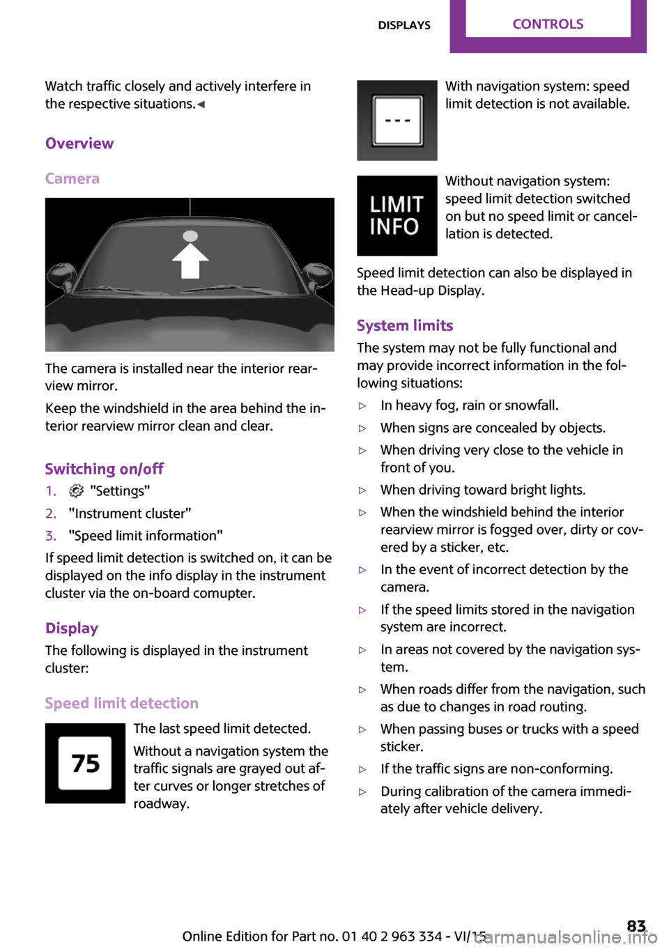
Camera
The camera is installed near the interior rear‐
view mirror.
Keep the windshield in the area behind the in‐
terior rearview mirror clean and clear.
Switching on/off
1. "Settings"2."Instrument cluster"3."Speed limit information"
If speed limit detection is switched on, it can be
displayed on the info display in the instrument
cluster via the on-board comupter.
Display The following is displayed in the instrument
cluster:
Speed limit detection The last speed limit detected.
Without a navigation system the
traffic signals are grayed out af‐
ter curves or longer stretches of
roadway.
With navigation system: speed
limit detection is not available.
Without navigation system:
speed limit detection switched
on but no speed limit or cancel‐
lation is detected.
Speed limit detection can also be displayed in
the Head-up Display.
System limits The system may not be fully functional and
may provide incorrect information in the fol‐
lowing situations:▷In heavy fog, rain or snowfall.▷When signs are concealed by objects.▷When driving very close to the vehicle in
front of you.▷When driving toward bright lights.▷When the windshield behind the interior
rearview mirror is fogged over, dirty or cov‐
ered by a sticker, etc.▷In the event of incorrect detection by the
camera.▷If the speed limits stored in the navigation
system are incorrect.▷In areas not covered by the navigation sys‐
tem.▷When roads differ from the navigation, such
as due to changes in road routing.▷When passing buses or trucks with a speed
sticker.▷If the traffic signs are non-conforming.▷During calibration of the camera immedi‐
ately after vehicle delivery.Seite 83DisplaysCONTROLS83
Online Edition for Part no. 01 40 2 963 334 - VI/15
Page 84 of 246
Selection lists in the in‐
strument cluster
The concept
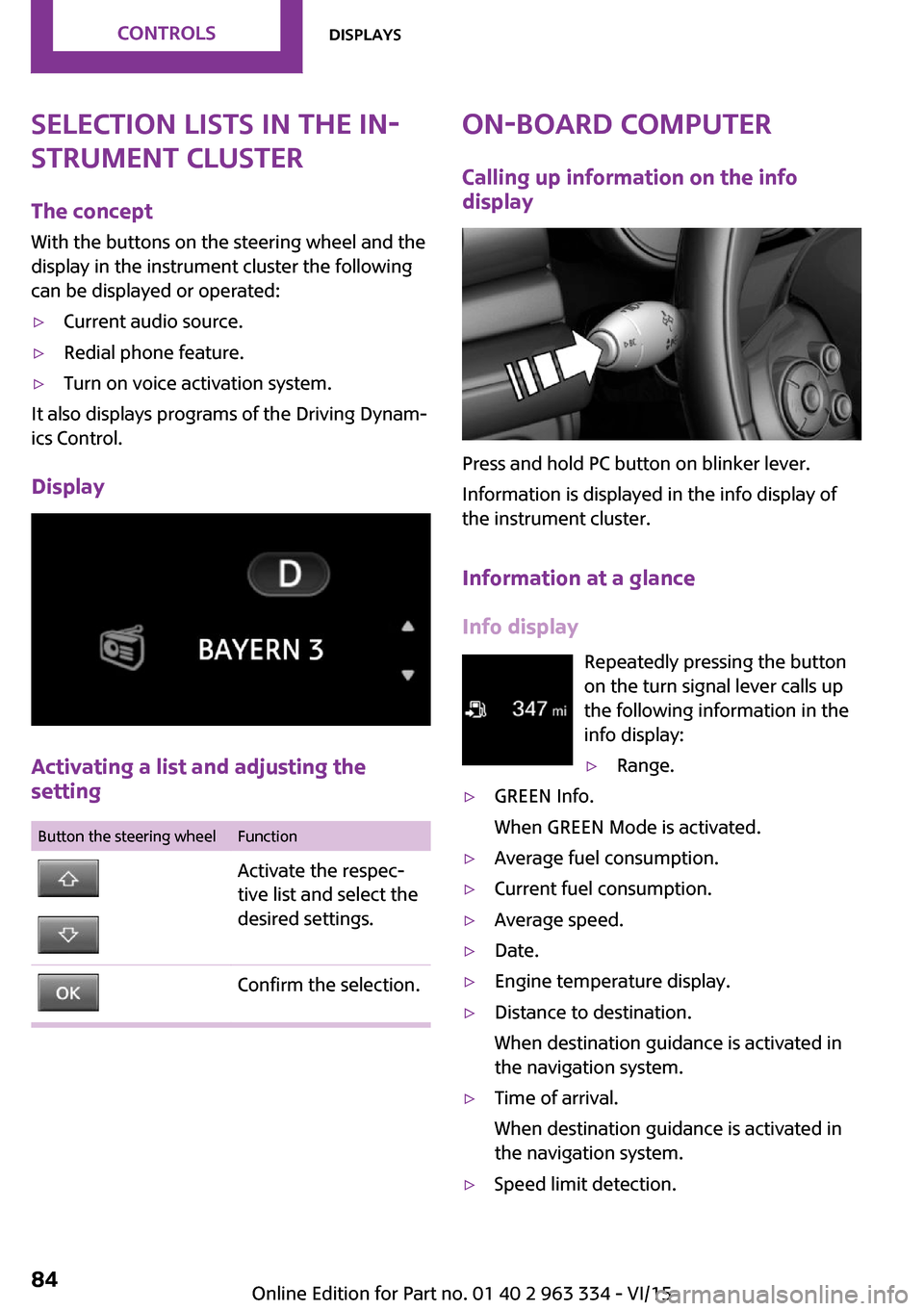
With the buttons on the steering wheel and the
display in the instrument cluster the following
can be displayed or operated:▷Current audio source.▷Redial phone feature.▷Turn on voice activation system.
It also displays programs of the Driving Dynam‐
ics Control.
Display
Activating a list and adjusting the
setting
Button the steering wheelFunctionActivate the respec‐
tive list and select the
desired settings.Confirm the selection.On-board computer
Calling up information on the info
display
Press and hold PC button on blinker lever.
Information is displayed in the info display of
the instrument cluster.
Information at a glance
Info display Repeatedly pressing the button
on the turn signal lever calls up
the following information in the
info display:
▷Range.▷GREEN Info.
When GREEN Mode is activated.▷Average fuel consumption.▷Current fuel consumption.▷Average speed.▷Date.▷Engine temperature display.▷Distance to destination.
When destination guidance is activated in
the navigation system.▷Time of arrival.
When destination guidance is activated in
the navigation system.▷Speed limit detection.Seite 84CONTROLSDisplays84
Online Edition for Part no. 01 40 2 963 334 - VI/15
Page 85 of 246
▷Speed.
Adjusting the info display
You can select what information from the on-
board comupter is to be displayed on the info
display of the instrument cluster.
On the Control Display:
1. "Settings"2."Instrument cluster"3.Select the desired displays.
Information in detail
Range
Displays the estimated cruising range available
with the remaining fuel.
It is calculated based on your driving style over
the last 20 miles/30 km.
GREEN info Description of GREEN info, refer to page 167.
Average fuel consumption
This is calculated for the period while the en‐
gine is running.
The average fuel consumption is calculated for
the distance traveled since the last reset by the
on-board comupter.
Average speed
Periods in which the vehicle is parked with the
engine manually stopped are not included in
the calculation of the average speed.
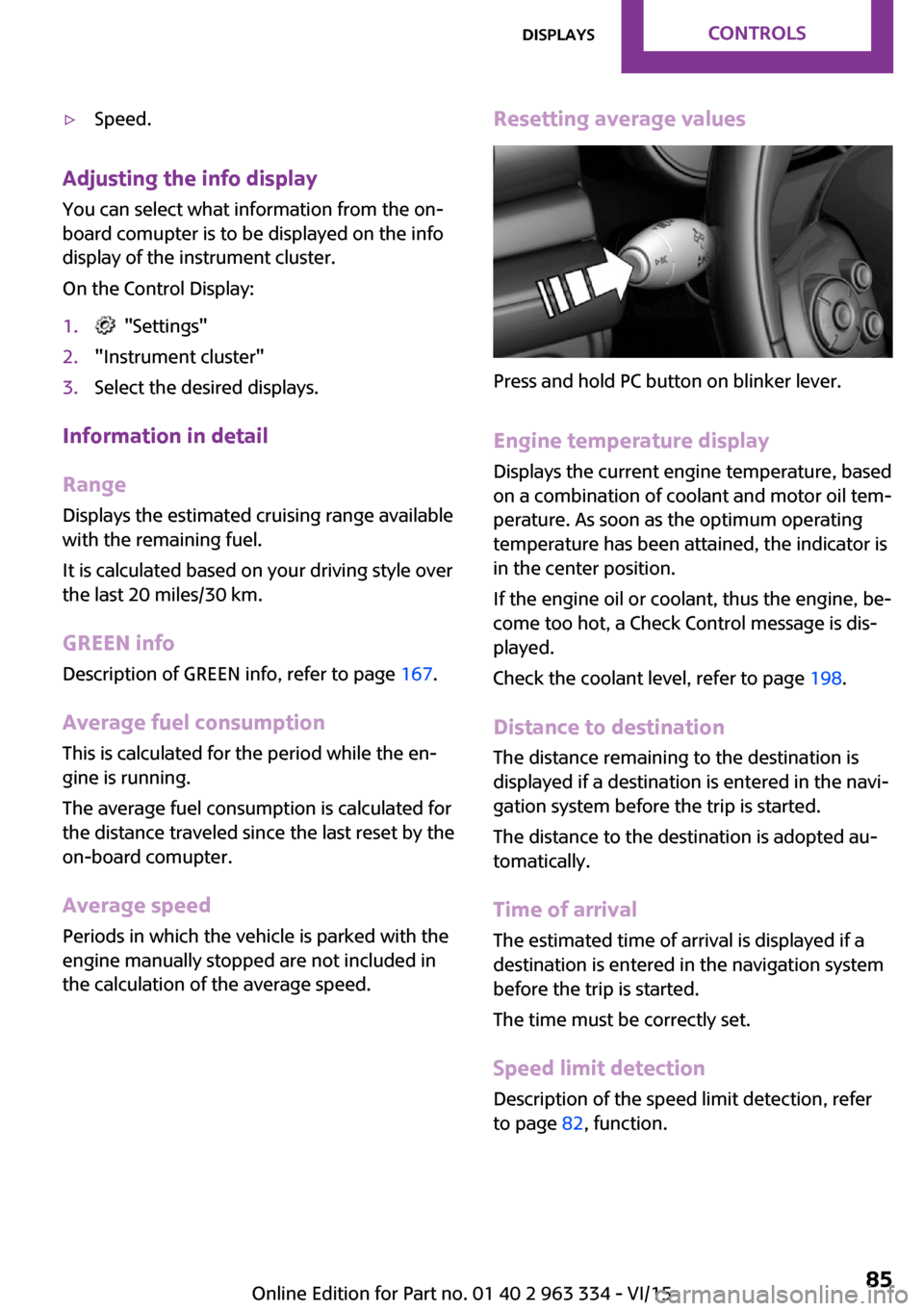
Resetting average values
Press and hold PC button on blinker lever.
Engine temperature display Displays the current engine temperature, based
on a combination of coolant and motor oil tem‐
perature. As soon as the optimum operating
temperature has been attained, the indicator is
in the center position.
If the engine oil or coolant, thus the engine, be‐
come too hot, a Check Control message is dis‐
played.
Check the coolant level, refer to page 198.
Distance to destination The distance remaining to the destination is
displayed if a destination is entered in the navi‐
gation system before the trip is started.
The distance to the destination is adopted au‐
tomatically.
Time of arrival The estimated time of arrival is displayed if a
destination is entered in the navigation system
before the trip is started.
The time must be correctly set.
Speed limit detection
Description of the speed limit detection, refer
to page 82, function.
Seite 85DisplaysCONTROLS85
Online Edition for Part no. 01 40 2 963 334 - VI/15
Page 86 of 246
Trip on-board computerThe vehicle features two types of on-board
computers.▷"Onboard info": the values can be reset as
often as necessary.▷"Trip computer": the values provide an
overview of the current trip.
Resetting the trip on-board computer
On the Control Display:
1. "Vehicle info"2."Trip computer"3."Reset": all values are reset.
"Automatically reset": all values are reset
approx. 4 hours after the vehicle came to a
standstill.
Display on the Control Display
Display the on-board comupter or trip on-
board computer on the Control Display.
On the Control Display:
1. "Vehicle info"2."Onboard info" or "Trip computer"
Resetting the fuel consumption and
speed
On the Control Display:
1. "Vehicle info"2."Onboard info"3."Consumpt." or "Speed"4."Yes"
Driving Excitement
The concept
On the Control Display, sport instruments can
be displayed, and the vehicle condition can be
checked before the use of the SPORT program.
Sport instruments
On the Control Display, values for power and
torque are displayed.
Displaying sport instruments
Via onboard monitor:1. "Vehicle info"2."Driving Excitement"3. "Sports instruments"
Via the Driving Dynamics Control
1.Activating SPORT.2. "Driving Excitement"3. "Sports instruments"
Vehicle state
The following vehicle and surrounding area
data are automatically checked and evaluated
in succession:
▷Range.▷Engine temperature.▷External temperature.▷SPORT program state.
Finally, a total evaluation of the vehicle state is
displayed.
Checking vehicle state
Via onboard monitor:
1. "Vehicle info"2."Driving Excitement"3. "Vehicle and surroundings"
Via the Driving Dynamics Control
1.Activating SPORT.2. "Driving Excitement"3. "Vehicle and surroundings"Seite 86CONTROLSDisplays86
Online Edition for Part no. 01 40 2 963 334 - VI/15
Page 87 of 246
Speed warning
The concept
Displays speed limit which, when reached,
should cause a warning to be issued.
The warning is repeated if the vehicle speed
drops below the set speed limit once by at least
3 mph/5 km/h.
Displaying, setting or changing the
limit
On the Control Display:1. "Settings"2."Speed"3."Warning at:"4.Turn the controller until the desired limit is
displayed.5.Press the controller.
The speed limit is stored.
Activating/deactivating the limit On the Control Display:
1. "Settings"2."Speed"3."Warning"4.Press the controller.
Setting your current speed as the limit On the Control Display:
1. "Settings"2."Speed"3."Select current speed"4.Press the controller.
The current vehicle speed is stored as the
limit.Settings on the Control
Display
Time
Setting the time zone1. "Settings"2."Time/Date"3."Time zone:"4.Select the desired time zone.
The time zone is stored.
Setting the time
1. "Settings"2."Time/Date"3."Time:"4.Turn the controller until the desired hours
are displayed.5.Press the controller.6.Turn the controller until the desired mi‐
nutes are displayed.7.Press the controller.
The time is stored.
Setting the time format
1. "Settings"2."Time/Date"3."Format:"4.Select the desired format.
The time format is stored.
Date
Setting the date
1. "Settings"2."Time/Date"3."Date:"4.Turn the controller until the desired day is
displayed.Seite 87DisplaysCONTROLS87
Online Edition for Part no. 01 40 2 963 334 - VI/15
Page 88 of 246
5.Press the controller.6.Make the necessary settings for the month
and year.
The date is stored.
Setting the date format
1. "Settings"2."Time/Date"3."Format:"4.Select the desired format.
The date format is stored.
Language
Setting the language
To set the language on the Control Display:
1. "Settings"2."Language/Units"3."Language:"4.Select the desired language.
Settings are stored for the profile currently
used.
Setting the voice dialog Voice dialog for the voice activation system, re‐
fer to page 27.
Units of measurement
Setting the units of measurement
To set the units for fuel consumption, route/
distance and temperature:
1. "Settings"2."Language/Units"3.Select the desired menu item.4.Select the desired unit.
Settings are stored for the profile currently
used.
Brightness
Setting the brightness To set the brightness of the Control Display:1. "Settings"2."Control display"3."Brightness"4.Turn the controller until the desired bright‐
ness is set.5.Press the controller.
Settings are stored for the profile currently
used.
Depending on the light conditions, the bright‐
ness settings may not be clearly visible.
LED ring on the central
instrument cluster
The concept
The LED ring displays light animations to repre‐
sent specific functions.
Basic displays
Basic functions, for example the tachometer,
can be set to be displayed continually if so de‐
sired.
Event displays Functions that are only displayed temporarily,
for example the volume or temperature set‐ tings, can be set as event displays.
Several vehicle assistance functions can also be displayed on the LED ring. This display corre‐
sponds with the displays of the function in the
respective display.
Example: tachometer Like the tachometer in the instrument cluster,
the light animations of the tachometer's basic
display show the current RPMs and the respec‐
tive RPM warning margins.
Seite 88CONTROLSDisplays88
Online Edition for Part no. 01 40 2 963 334 - VI/15
Page 89 of 246
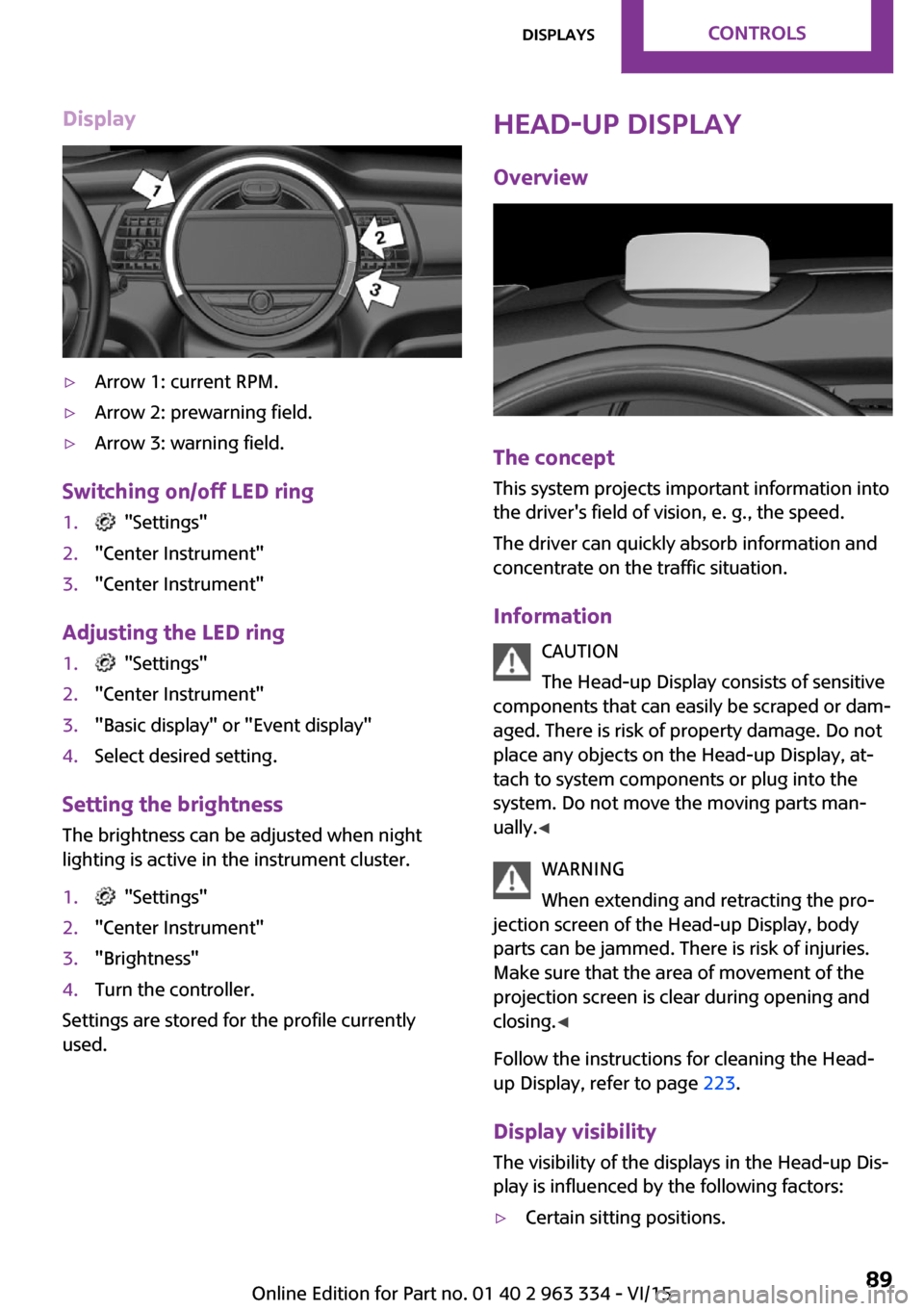
Display▷Arrow 1: current RPM.▷Arrow 2: prewarning field.▷Arrow 3: warning field.
Switching on/off LED ring
1. "Settings"2."Center Instrument"3."Center Instrument"
Adjusting the LED ring
1. "Settings"2."Center Instrument"3."Basic display" or "Event display"4.Select desired setting.
Setting the brightnessThe brightness can be adjusted when night
lighting is active in the instrument cluster.
1. "Settings"2."Center Instrument"3."Brightness"4.Turn the controller.
Settings are stored for the profile currently
used.
Head-up Display
Overview
The concept
This system projects important information into
the driver's field of vision, e. g., the speed.
The driver can quickly absorb information and
concentrate on the traffic situation.
Information CAUTION
The Head-up Display consists of sensitive
components that can easily be scraped or dam‐
aged. There is risk of property damage. Do not
place any objects on the Head-up Display, at‐
tach to system components or plug into the
system. Do not move the moving parts man‐
ually. ◀
WARNING
When extending and retracting the pro‐
jection screen of the Head-up Display, body
parts can be jammed. There is risk of injuries.
Make sure that the area of movement of the
projection screen is clear during opening and
closing. ◀
Follow the instructions for cleaning the Head-
up Display, refer to page 223.
Display visibility
The visibility of the displays in the Head-up Dis‐
play is influenced by the following factors:
▷Certain sitting positions.Seite 89DisplaysCONTROLS89
Online Edition for Part no. 01 40 2 963 334 - VI/15
Page 90 of 246
▷Objects on the cover of the Head-up Dis‐
play.▷Sunglasses with certain polarization filters.▷Wet roads.▷Unfavorable light conditions.
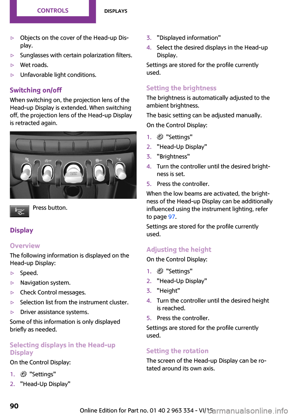
Switching on/off
When switching on, the projection lens of the
Head-up Display is extended. When switching
off, the projection lens of the Head-up Display
is retracted again.
Press button.
Display
Overview
The following information is displayed on the
Head-up Display:
▷Speed.▷Navigation system.▷Check Control messages.▷Selection list from the instrument cluster.▷Driver assistance systems.
Some of this information is only displayed
briefly as needed.
Selecting displays in the Head-up
Display
On the Control Display:
1. "Settings"2."Head-Up Display"3."Displayed information"4.Select the desired displays in the Head-up
Display.
Settings are stored for the profile currently
used.
Setting the brightness The brightness is automatically adjusted to the
ambient brightness.
The basic setting can be adjusted manually.
On the Control Display:
1. "Settings"2."Head-Up Display"3."Brightness"4.Turn the controller until the desired bright‐
ness is set.5.Press the controller.
When the low beams are activated, the bright‐
ness of the Head-up Display can be additionally
influenced using the instrument lighting, refer
to page 97.
Settings are stored for the profile currently
used.
Adjusting the height On the Control Display:
1. "Settings"2."Head-Up Display"3."Height"4.Turn the controller until the desired height
is reached.5.Press the controller.
Settings are stored for the profile currently
used.
Setting the rotation The screen of the Head-up Display can be ro‐
tated around its own axis.
Seite 90CONTROLSDisplays90
Online Edition for Part no. 01 40 2 963 334 - VI/15