hood open MINI Hardtop 4 Door 2016 Owner's Manual (Mini Connected)
[x] Cancel search | Manufacturer: MINI, Model Year: 2016, Model line: Hardtop 4 Door, Model: MINI Hardtop 4 Door 2016Pages: 246, PDF Size: 6.36 MB
Page 43 of 246
3. Select the symbol.4.Select the desired function.▷"Tailgate"
Only the tailgate is unlocked.▷"Tailgate + door(s)"
The tailgate and the doors are un‐
locked.
Locking
The settings are saved in the active profile. Per‐
sonal Profile, refer to page 36.
1. "Settings"2."Doors/key"3.Select desired setting.▷"Lock if no door is opened"
The vehicle locks automatically after a
short period of time if no door is
opened.▷"Lock after start driving"
The vehicle locks automatically after
you drive off.
Confirmation signals from the vehicle
1. "Settings"2."Doors/key"3.Select desired setting.▷"Acoustic sig. lock/unlock"
Unlocking is signaled by one honk of
the horn.▷"Flash when lock/unlock"
Unlocking is signaled by two flashes,
locking by one.
Alarm system
The concept
When the vehicle is locked, the vehicle alarm
system responds to:
▷Opening a door, the hood or the tailgate.▷Movements in the vehicle interior.▷Changes in the vehicle tilt, e. g., during at‐
tempts at stealing a wheel or when towing
the car.▷Disconnected battery voltage.
The alarm system briefly signals tampering:
▷Acoustic alarm.▷By switching on the hazard warning system.▷By flashing the daytime running lights.
Arming and disarming the alarm system
When you lock or unlock the vehicle, either
with the remote control or via the Comfort Ac‐
cess, the alarm system is armed or disarmed at
the same time.
Door lock and armed alarm system
The alarm system is triggered when the door is
opened, when the vehicle is unlocked via the
door lock.
Switch off the alarm, refer to page 44.
Tailgate in case of armed alarm system The tailgate can be opened even when the
alarm system is armed.
After the tailgate is closed, it is locked and
monitored again when the doors are locked.
The hazard warning system flashes once.
Panic mode You can trigger the alarm system if you findyourself in a dangerous situation.
Press button on the remote control for
at least 3 seconds.
To switch off the alarm: press any button.
Seite 43Opening and closingCONTROLS43
Online Edition for Part no. 01 40 2 963 334 - VI/15
Page 44 of 246

Indicator lamp on the interior rearview
mirror▷The indicator lamp flashes briefly every
2 seconds:
The alarm system is armed.▷The indicator lamp flashes after locking:
Doors, hood or tailgate are not correctly
closed. Correctly closed access points are
secured.
After 10 seconds, the indicator lamp flashes
continuously. Interior motion sensor and tilt
alarm sensor are not active.
When the still open access is closed, interior
motion sensor and tilt alarm sensor will be
switched on.▷The indicator lamp goes out after unlock‐
ing:
The vehicle has not been tampered with.▷The indicator lamp flashes after unlocking
until the engine ignition is switched on, but
no longer than approx. 5 minutes:
An alarm has been triggered.
Tilt alarm sensor The tilt of the vehicle is monitored.
The alarm system responds in situations such as
attempts to steal a wheel or when the car is
towed.
Interior motion sensor The windows and glass sunroof must be closed
for the system to function properly.
Avoiding unintentional alarms
The tilt alarm sensor and interior motion sensor
can be switched off together, such as in the fol‐
lowing situations:▷In automatic car washes.▷In duplex garages.▷During transport on trains carrying vehicles,
at sea or on a trailer.▷With animals in the vehicle.
Switching off the tilt alarm sensor and
interior motion sensor
Press the remote control button again
within 10 seconds as soon as the vehi‐
cle is locked.
The indicator lamp lights up for approx. 2 sec‐
onds and then continues to flash.
The tilt alarm sensor and interior motion sensor
are turned off until the vehicle is locked again.
Switching off the alarm
▷Unlock vehicle with the remote control or
switch on the ignition, if needed through
emergency detection of remote control, re‐
fer to page 35.▷For Comfort Access: If you have the remote
control with you, unlock vehicle using the
button on the driver's side or passenger
side door.
Power windows
Information WARNING
Unattended children or animals can move
the vehicle and endanger themselves and traf‐
fic, e.g. with the following actions:
▷Pressing the Start/Stop button.▷Releasing the parking brake.▷Opening and closing of doors or windows.Seite 44CONTROLSOpening and closing44
Online Edition for Part no. 01 40 2 963 334 - VI/15
Page 65 of 246

▷The driver's safety belt is buckled or the
driver's door is closed.
In order to be able to release the brake pedal,
engage lever in position P. The engine remains
off.
To continue driving depress the brake pedal.
When a gear is engaged, the engine starts au‐
tomatically.
The air flow from the air conditioner is reduced
when the engine is switched off.
Displays in the instrument cluster The display indicates that theAuto Start/Stop function is ready
for an Automatic engine start.
The display indicates that the
conditions for an automatic en‐
gine stop have not been met.
Functional limitations The engine is not switched off automatically in
the following situations:
▷External temperature too low.▷The external temperature is high and auto‐
matic climate control is running.▷The car's interior has not yet been heated
or cooled to the required level.▷The engine is not yet at operating tempera‐
ture.▷The wheels are at a sharp angle or the
steering wheel is being turned.▷After driving in reverse.▷Fogging of the windows when the auto‐
matic climate control is switched on.▷The vehicle battery charge is very low.▷At higher elevations.▷The engine compartment lid is unlocked.▷The parking assistant is activated.▷Stop-and-go traffic.▷Selector lever in selector lever position R, N
or M/S.
Starting the engine
The engine starts automatically under the fol‐
lowing conditions:
▷Manual transmission:
The clutch pedal is pressed.▷Steptronic transmission:
By releasing the brake pedal.
After the engine starts, accelerate as usual.
Safety mode
After the engine switches off automatically, it
will not start again automatically if any one of
the following conditions are met:
▷The driver's safety belt is unbuckled and
the driver's door is open.▷The hood was unlocked.
Some indicator lights light up for a varied
length of time.
The engine can only be started via the Start/
Stop button.
Functional limitations
Even if driving off was not intended, the deacti‐
vated engine starts up automatically in the fol‐
lowing situations:
▷Excessive warming of the car's interior
when the cooling function is switched on.▷The steering wheel is turned.▷Steptronic transmission: change from selec‐
tor lever position D to R, N or M/S.▷Steptronic transmission: change from selec‐
tor lever position P to R, N, D or M/S.▷The vehicle begins rolling.▷Fogging of the windows when the auto‐
matic climate control is switched on.Seite 65DrivingCONTROLS65
Online Edition for Part no. 01 40 2 963 334 - VI/15
Page 194 of 246
Hood
Information WARNING
Improperly executed work in the engine
compartment can damage components and
lead to a safety risk. There is risk of accidents or
risk of property damage. ◀
WARNING
The engine compartment accommodates
moving components. Certain components can
move in the engine compartment with the ve‐
hicle switched off, e.g. the cooler fan. There is
risk of injuries. Do not reach into the area of
moving parts. Keep articles of clothing and hair
away from moving parts. ◀
CAUTION
Folded-away wipers can be jammed
when the hood is opened. There is risk of prop‐
erty damage. Make sure that the wipers with
the wiper blades mounted are folded down onto the windshield before opening the
hood. ◀
WARNING
There are protruding parts, e.g. lock
hook, on the inside of the hood. There is risk of
injuries. If the hood is open, pay attention to
protruding parts and keep these areas clear. ◀
WARNING
An incorrectly locked hood can open
while driving and restrict visibility. There is risk
of an accident. Stop immediately and correctly
close the hood. ◀
WARNING
Body parts can be jammed on opening
and closing the hood. There is risk of injuries.
Make sure that the area of movement of the
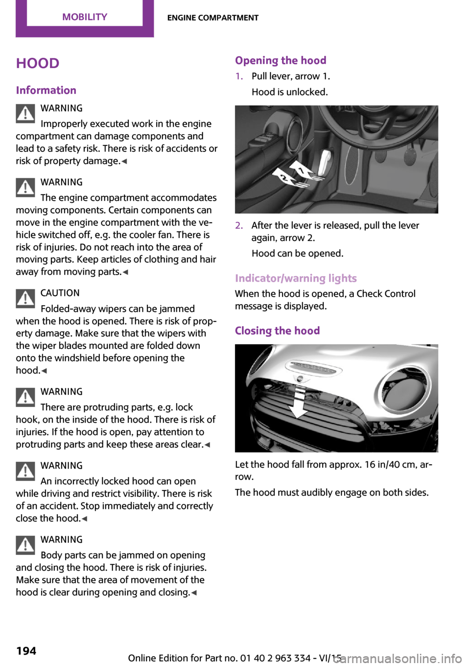
hood is clear during opening and closing. ◀Opening the hood1.Pull lever, arrow 1.
Hood is unlocked.2.After the lever is released, pull the lever
again, arrow 2.
Hood can be opened.
Indicator/warning lights
When the hood is opened, a Check Control
message is displayed.
Closing the hood
Let the hood fall from approx. 16 in/40 cm, ar‐
row.
The hood must audibly engage on both sides.
Seite 194MOBILITYEngine compartment194
Online Edition for Part no. 01 40 2 963 334 - VI/15
Page 196 of 246

CAUTION
Too much engine oil can damage the en‐
gine or the catalytic converter. There is risk of
property damage. Do not add too much engine
oil. Have too much engine oil siphoned off by a
dealer’s service center or another qualified
service center or repair shop. ◀
Detailed measurement
The concept
In the detailed measurement the engine oil
level is checked and displayed via a scale.
If the engine oil level reaches the minimum
level, a check control message is displayed.
During the measurement, the idle speed is in‐
creased somewhat.
Requirements▷Vehicle is on level road.▷Manual transmission: shift lever in neutral
position, clutch and accelerator pedals not
depressed.▷Steptronic transmission: selector lever in se‐
lector lever position N or P and accelerator
pedal not depressed.▷Engine is running and is at operating tem‐
perature.
Performing a detailed measurement
On the Control Display:
1. "Vehicle info"2."Vehicle status"3. "Measure engine oil level"4."Start measurement"
The engine oil level is checked and displayed
via a scale.
Time: approx. 1 minute.
Adding engine oil
Information CAUTION
A too low engine oil level causes engine
damage. There is risk of property damage.
Add engine oil within the next
125 miles/200 km. ◀
CAUTION
Too much engine oil can damage the en‐
gine or the catalytic converter. There is risk of
property damage. Do not add too much engine
oil. Have too much engine oil siphoned off by a
dealer’s service center or another qualified
service center or repair shop. ◀
WARNING
Operating materials, e.g. oils, greases,
coolants, fuels, can contain harmful ingredi‐
ents. There is risk of injuries or danger to life.
Observe the instructions on the containers. Avoid the contact of articles of clothing, skin or
eyes with operating materials. Do not refill op‐
erating materials into different bottles. Store
operating materials out of reach of children. ◀
General information
Only add engine oil when the message is dis‐
played in the instrument cluster. The quantity
to be added is indicated in the message dis‐
played in the instrument cluster.
Switch off the ignition and safely park the vehi‐
cle before engine oil is added.
Overview The oil filler neck is located in the engine com‐
partment, refer to page 193.
Opening the oil filler neck1.Open the hood, refer to page 194.Seite 196MOBILITYEngine oil196
Online Edition for Part no. 01 40 2 963 334 - VI/15
Page 198 of 246

CoolantVehicle features and op‐
tions
This chapter describes all standard, country-
specific and optional features offered with the
series. It also describes features that are not
necessarily available in your car, e. g., due to
the selected options or country versions. This
also applies to safety-related functions and sys‐
tems. The respectively applicable country provi‐
sions must be observed when using the respec‐
tive features and systems.
Information WARNING
With the engine hot and the cooling sys‐
tem open, coolant can escape and lead to
burns. There is risk of injuries. Only open the cooling system with the engine cooled down. ◀
WARNING
Additives are harmful and incorrect addi‐
tives can damage the engine. There is risk of in‐
juries and risk of property damage. Avoid the
contact of articles of clothing, skin or eyes with
additives. Do not swallow any additives. Use
suitable additives only. ◀
Coolant consists of water and additives.
Not all commercially available additives are
suitable for the vehicle. Information about suit‐
able additives is available from a dealer’s serv‐
ice center or another qualified service center or
repair shop.
Coolant level
Overview Opening the hood, refer to page 194The coolant reservoir is in the engine compart‐
ment, refer to page 193.
Checking
There are yellow Min and Max marks in the
coolant reservoir.1.Let the engine cool.2.Turn the lid of the coolant reservoir slightly
counterclockwise to allow any excess pres‐
sure to dissipate, then open it.3.The coolant level is correct if it lies between
the minimum and maximum marks in the
filler neck.Seite 198MOBILITYCoolant198
Online Edition for Part no. 01 40 2 963 334 - VI/15
Page 202 of 246

Replacing componentsVehicle features and op‐
tions
This chapter describes all standard, country-
specific and optional features offered with the
series. It also describes features that are not
necessarily available in your car, e. g., due to
the selected options or country versions. This
also applies to safety-related functions and sys‐
tems. The respectively applicable country provi‐
sions must be observed when using the respec‐
tive features and systems.
Onboard vehicle tool kit
The onboard vehicle tool kit is located in the
trough under the trunk floor.
The warning triangle is located in the tailgate.
To remove, loosen the brackets.
Wiper blade replacement
Information CAUTION
If the wiper arm falls onto the windshield
without the wiper blades installed, the wind‐
shield can be damaged. There is risk of prop‐
erty damage. Secure the wiper arm when re‐
placing the wiper blades and do not fold down
the wipers without the wiper blades installed. ◀
CAUTION
Folded-away wipers can be jammed
when the hood is opened. There is risk of prop‐
erty damage. Make sure that the wipers with
the wiper blades mounted are folded down
onto the windshield before opening the
hood. ◀
Replacing the front wiper blades1.Fold up and hold the wiper arm firmly.2.Open the wiper blade lock, arrow.3.Pull the wiper blade down first out of the
holder on the wiper arm, arrow 1.Seite 202MOBILITYReplacing components202
Online Edition for Part no. 01 40 2 963 334 - VI/15
Page 205 of 246
LED low beams/LED high beamsFollow the general instructions on lights and
bulbs, refer to page 203.
The lights feature LED technology. Contact a
dealer’s service center or another qualified
service center or repair shop in the event of a
malfunction.
Halogen low beams/halogen high
beams
Follow the general instructions on lights and
bulbs, refer to page 203.
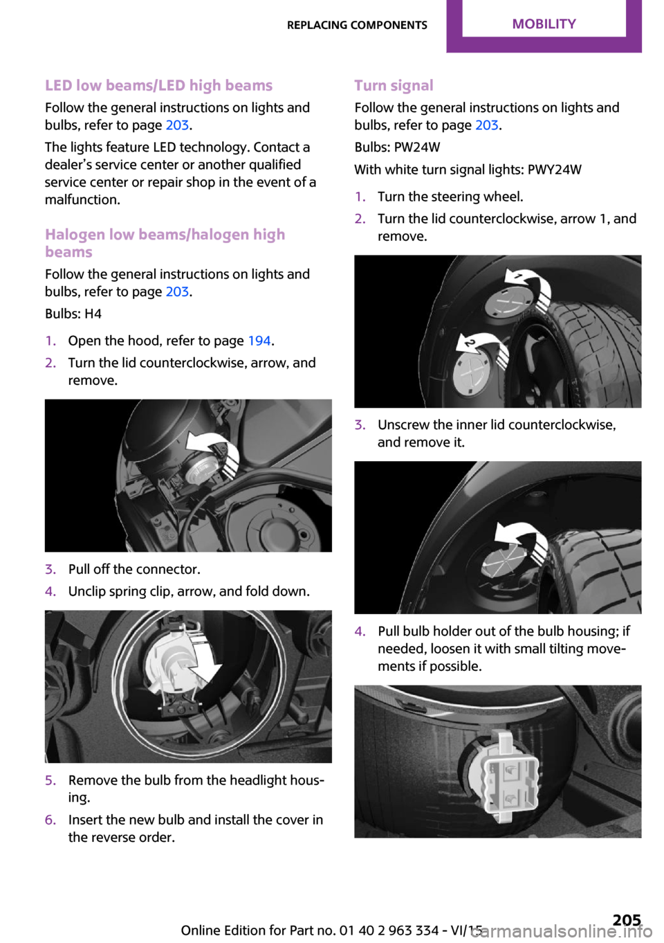
Bulbs: H41.Open the hood, refer to page 194.2.Turn the lid counterclockwise, arrow, and
remove.3.Pull off the connector.4.Unclip spring clip, arrow, and fold down.5.Remove the bulb from the headlight hous‐
ing.6.Insert the new bulb and install the cover in
the reverse order.Turn signal
Follow the general instructions on lights and
bulbs, refer to page 203.
Bulbs: PW24W
With white turn signal lights: PWY24W1.Turn the steering wheel.2.Turn the lid counterclockwise, arrow 1, and
remove.3.Unscrew the inner lid counterclockwise,
and remove it.4.Pull bulb holder out of the bulb housing; if
needed, loosen it with small tilting move‐
ments if possible.Seite 205Replacing componentsMOBILITY205
Online Edition for Part no. 01 40 2 963 334 - VI/15
Page 209 of 246

The wire is long enough to guide the socket
down and through between any heat shield
that may be installed and the bumper.4.Replace nonworking bulb.5.To install the new bulb, proceed in reverse
order of removal.
Right fog lamp:
1.Turn the bulb socket counterclockwise and
remove.
The wire is long enough to guide the socket
down and through between any heat shield
that may be installed and the bumper.2.Replace nonworking bulb.3.To install the new bulb, proceed in reverse
order of removal.
Side turn signal, bulb replacement
Follow the general instructions on lights and
bulbs, refer to page 203.
Bulbs:
▷With orange lens: W5W▷With white lens: WY5W diadem1.Open the hood. The covers of the side turn
signal lights are on the left and right next to
the hinges of the hood.2.Loosen nuts of the cover by hand and re‐
move the cover.3.Turn the bulb holder counterclockwise and
remove.4.Replace the bulb.5.To insert the new bulb, proceed in reverse
order of removal. Insert the nuts of the
cover and press down.Seite 209Replacing componentsMOBILITY209
Online Edition for Part no. 01 40 2 963 334 - VI/15
Page 239 of 246

Fold-out position, windshieldwipers 70
Foot brake 159
Front airbags 99
Front-end collision warning with City Braking func‐
tion 109
Front fog lights 97
Front-seat passenger airbags, automatic deactivation 101
Front-seat passenger airbags, indicator lamp 101
FTM Flat Tire Monitor 106
Fuel 176
Fuel consumption, see Aver‐ age fuel consumption 85
Fuel filler flap 174
Fuel gauge 80
Fuel lid 174
Fuel quality 176
Fuel recommendation 176
Fuel, tank capacity 230
Fuse 213
G Garage door opener, see Uni‐ versal Integrated Remote
Control 143
Gasoline 176
Gear change, Steptronic trans‐ mission 71
Gear shift indicator 82
General driving notes 158
Glare shield 147
Glass sunroof, refer to Panor‐ amic glass sunroof 46
Glove compartment 151
GREEN mode 165
GREEN mode, bonus range 167
GREEN mode driving style analysis 169
GREEN mode indicator 165
GREEN - program, driving dy‐ namics 117 GREEN tip 167
Gross vehicle weight, ap‐ proved 227
Ground clearance 160
H
Halogen headlights 204
Handbrake, refer to parking brake 66
Hand-held transmitter, alter‐ nating code 144
Hazard warning flashers 214
Head airbag 99
Headlight control, auto‐ matic 95
Headlight courtesy delay fea‐ ture 95
Headlight flasher 67
Headlight glass 204
Headlights, care 221
Head restraints 49
Head restraints, front 53
Head restraints, rear 54
Head-up Display 89
Head-Up Display, Shift point indicator 91
Head-up Display, sport dis‐ plays 91
Head-up Display, standard view 90
Heavy cargo, stowing 162
High-beam Assistant 96
High beams 67
High beams/low beams, see High-beam Assistant 96
Hills 160
Hill start assistant, see Drive- off assistant 118
Holder for beverages 152
Homepage 6
Hood 194
Horn 14
Hot exhaust system 159
HUD Head-up Display 89
Hydroplaning 159 I
Ice warning, see External tem‐ perature warning 80
Icy roads, see External tem‐ perature warning 80
Identification marks, tires 184
Identification number, see ve‐ hicle identification num‐
ber 10
Ignition key, see Remote con‐ trol 34
Ignition off 62
Ignition on 62
Illuminated ring, central in‐ strument cluster 88
Indication of a flat tire 103 , 106
Indicator lamp, see Check Control 76
Individual air distribu‐ tion 137, 140
Individual settings, see Per‐ sonal Profile 36
Inflation pressure, tires 178
Inflation pressure warning, tires 106
Info display, refer to On-Board computer 84
Information 6
Initialize, Tire Pressure Moni‐ tor TPM 103
Initializing, Flat Tire Monitor FTM 106
Instrument cluster 75
Instrument cluster, electronic displays 76
Instrument lighting 97
Integrated key 34
Integrated Owner's Manual in the vehicle 29
Intelligent Safety 108
Intensity, AUTO program 139
Interior equipment 143
Interior lights 98 Seite 239Everything from A to ZREFERENCE239
Online Edition for Part no. 01 40 2 963 334 - VI/15