tow MINI Hardtop 4 Door 2016 Owner's Manual (Mini Connected)
[x] Cancel search | Manufacturer: MINI, Model Year: 2016, Model line: Hardtop 4 Door, Model: MINI Hardtop 4 Door 2016Pages: 246, PDF Size: 6.36 MB
Page 39 of 246

▷The battery of the remote control is dis‐
charged. Replace the battery, refer to
page 34.▷Interference of the radio connection from
transmission towers or other equipment
with high transmit power.▷Shielding of the remote control due to
metal objects.▷Interference of the radio connection from
mobile phones or other electronic devices
in direct proximity.
Do not transport the remote control together
with metal objects or electronic devices.
In the case of a malfunction, unlock and lock
the vehicle using the integrated key, refer to
page 39.
For US owners only The transmitter and receiver units comply with
part 15 of the FCC/Federal Communication
Commission regulations. Operation is governed by the following:
FCC ID:
▷LX8766S.▷LX8766E.▷LX8CAS.▷LX8CAS2.▷MYTCAS4.
Compliance statement:
This device complies with part 15 of the FCC
Rules. Operation is subject to the following two
conditions:
▷This device may not cause harmful interfer‐
ence, and▷this device must accept any interference re‐
ceived, including interference that may
cause undesired operation.
Any unauthorized modifications or changes to
these devices could void the user's authority to
operate this equipment.
Without remote control
From the outside WARNING
Unlocking from the inside is only possible
with special knowledge.
If people must spend a longer time in the vehi‐
cle while it is very hot or cold outside, there is
risk of injuries or danger to life. Do not lock the
vehicle from the outside when there are people
in it. ◀
CAUTION
The door lock is permanently joined with
the door. The door handle can be moved.
When pulling the door handle with the
integrated key inserted, paint or key can be
damaged. There is risk of property damage. Re‐
move the integrated key before pulling the
outside door handle. ◀
Unlock or lock the driver's door via the door
lock using the integrated key, refer to page 34.
The other doors must be unlocked or locked
from the inside.
To do this, unlock the lid from below with the
integrated key, arrow, and remove.
Alarm system
The alarm system is not armed if the vehicle is
locked with the integrated key.
The alarm system is triggered when the door is
opened, if the vehicle was unlocked via the
door lock. In order to terminate this alarm, un‐
lock vehicle with the remote control or switch
Seite 39Opening and closingCONTROLS39
Online Edition for Part no. 01 40 2 963 334 - VI/15
Page 42 of 246

To save battery power, ensure that all power
consumers are turned off before locking the ve‐
hicle.
Convenient closing WARNING
With convenient closing, body parts can
be jammed. There is risk of injuries. Make sure
that the area of movement of the doors is clear
during convenient closing. ◀
Press and hold down the handle of the driver or
the front seat passenger.
This corresponds to pressing the remote control
button:
In addition to locking, the windows and glass
sunroof will be closed.
Unlocking the tailgate separately Press button on tailgate's exterior.
This corresponds to pressing the remote control
button:
The situation of the doors does not change.
Malfunction Remote control detection by the vehicle can
among others be malfunctioning under the fol‐
lowing circumstances:
▷The battery of the remote control is dis‐
charged. Replace the battery, refer to
page 34.▷Interference of the radio connection from
transmission towers or other equipment
with high transmit power.▷Shielding of the remote control due to
metal objects.▷Interference of the radio connection from
mobile phones or other electronic devices
in direct proximity.
Do not transport the remote control together
with metal objects or electronic devices.
In the case of a malfunction, unlock and lock
the vehicle using the buttons of the remote
control or using the integrated key, refer to
page 39.
Adjusting Unlocking The settings are saved in the active profile. Per‐
sonal Profile, refer to page 36.
Doors
1. "Settings"2."Doors/key"3. Select the symbol.4.Select the desired function.▷"Driver's door only"
Only the driver's door and the fuel filler
flap are unlocked. Pressing again un‐
locks the entire vehicle.▷"All doors"
The entire vehicle is unlocked.
Tailgate
Depending on optional features and country
version, this setting is not offered in some
cases.
1. "Settings"2."Doors/key"Seite 42CONTROLSOpening and closing42
Online Edition for Part no. 01 40 2 963 334 - VI/15
Page 43 of 246

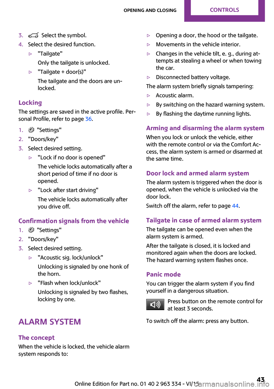
3. Select the symbol.4.Select the desired function.▷"Tailgate"
Only the tailgate is unlocked.▷"Tailgate + door(s)"
The tailgate and the doors are un‐
locked.
Locking
The settings are saved in the active profile. Per‐
sonal Profile, refer to page 36.
1. "Settings"2."Doors/key"3.Select desired setting.▷"Lock if no door is opened"
The vehicle locks automatically after a
short period of time if no door is
opened.▷"Lock after start driving"
The vehicle locks automatically after
you drive off.
Confirmation signals from the vehicle
1. "Settings"2."Doors/key"3.Select desired setting.▷"Acoustic sig. lock/unlock"
Unlocking is signaled by one honk of
the horn.▷"Flash when lock/unlock"
Unlocking is signaled by two flashes,
locking by one.
Alarm system
The concept
When the vehicle is locked, the vehicle alarm
system responds to:
▷Opening a door, the hood or the tailgate.▷Movements in the vehicle interior.▷Changes in the vehicle tilt, e. g., during at‐
tempts at stealing a wheel or when towing
the car.▷Disconnected battery voltage.
The alarm system briefly signals tampering:
▷Acoustic alarm.▷By switching on the hazard warning system.▷By flashing the daytime running lights.
Arming and disarming the alarm system
When you lock or unlock the vehicle, either
with the remote control or via the Comfort Ac‐
cess, the alarm system is armed or disarmed at
the same time.
Door lock and armed alarm system
The alarm system is triggered when the door is
opened, when the vehicle is unlocked via the
door lock.
Switch off the alarm, refer to page 44.
Tailgate in case of armed alarm system The tailgate can be opened even when the
alarm system is armed.
After the tailgate is closed, it is locked and
monitored again when the doors are locked.
The hazard warning system flashes once.
Panic mode You can trigger the alarm system if you findyourself in a dangerous situation.
Press button on the remote control for
at least 3 seconds.
To switch off the alarm: press any button.
Seite 43Opening and closingCONTROLS43
Online Edition for Part no. 01 40 2 963 334 - VI/15
Page 44 of 246

Indicator lamp on the interior rearview
mirror▷The indicator lamp flashes briefly every
2 seconds:
The alarm system is armed.▷The indicator lamp flashes after locking:
Doors, hood or tailgate are not correctly
closed. Correctly closed access points are
secured.
After 10 seconds, the indicator lamp flashes
continuously. Interior motion sensor and tilt
alarm sensor are not active.
When the still open access is closed, interior
motion sensor and tilt alarm sensor will be
switched on.▷The indicator lamp goes out after unlock‐
ing:
The vehicle has not been tampered with.▷The indicator lamp flashes after unlocking
until the engine ignition is switched on, but
no longer than approx. 5 minutes:
An alarm has been triggered.
Tilt alarm sensor The tilt of the vehicle is monitored.
The alarm system responds in situations such as
attempts to steal a wheel or when the car is
towed.
Interior motion sensor The windows and glass sunroof must be closed
for the system to function properly.
Avoiding unintentional alarms
The tilt alarm sensor and interior motion sensor
can be switched off together, such as in the fol‐
lowing situations:▷In automatic car washes.▷In duplex garages.▷During transport on trains carrying vehicles,
at sea or on a trailer.▷With animals in the vehicle.
Switching off the tilt alarm sensor and
interior motion sensor
Press the remote control button again
within 10 seconds as soon as the vehi‐
cle is locked.
The indicator lamp lights up for approx. 2 sec‐
onds and then continues to flash.
The tilt alarm sensor and interior motion sensor
are turned off until the vehicle is locked again.
Switching off the alarm
▷Unlock vehicle with the remote control or
switch on the ignition, if needed through
emergency detection of remote control, re‐
fer to page 35.▷For Comfort Access: If you have the remote
control with you, unlock vehicle using the
button on the driver's side or passenger
side door.
Power windows
Information WARNING
Unattended children or animals can move
the vehicle and endanger themselves and traf‐
fic, e.g. with the following actions:
▷Pressing the Start/Stop button.▷Releasing the parking brake.▷Opening and closing of doors or windows.Seite 44CONTROLSOpening and closing44
Online Edition for Part no. 01 40 2 963 334 - VI/15
Page 47 of 246

Overview
Tilting the glass sunroofPress back the switch up to or
beyond the resistance point and
release it.
The glass sunroof is raised.
Opening glass sunroof
When the glass sunroof is closed Press the switch back beyond
the resistance point and release
it twice.
The glass sunroof is opened.
Pressing the switch again stops
the motion.
With the glass sunroof completely
raised
▷Slide switch back to the re‐
sistance point and hold.
The glass sunroof is opened
as long as the switch is
pressed.▷Press the switch back beyond the resist‐
ance point and release it.
The glass sunroof is opened.
Pressing the switch again stops the motion.Comfort position
If the glass sunroof stops before it is completely
opened, it is in the Comfort position. In this po‐
sition the wind noises in the interior are the
least.
If desired, continue the movement by Pressing
the switch.
Closing glass sunroof
With the glass sunroof open▷Slide switch forward to the
resistance point and hold.
The glass sunroof is closed as
long as the switch is pressed
and stops in the raised posi‐
tion.▷Press the switch forward beyond the resist‐
ance point and release it.
The glass sunroof is closed and stops in the
raised position.
Pressing the switch toward the back stops
the motion.▷Press the switch forward beyond the resist‐
ance point and release it twice.
The glass sunroof is closed.
Pressing the switch again stops the motion.
With the glass sunroof completely
raised
Press the switch forward beyond
the resistance point and release
it.
The glass sunroof is closed.
Pinch protection system If the closing force exceeds a specific value as a
glass sunroof closes, the closing action is inter‐
rupted.
The glass sunroof reopens slightly.
Seite 47Opening and closingCONTROLS47
Online Edition for Part no. 01 40 2 963 334 - VI/15
Page 69 of 246

Activating/deactivating
Press button on the wiper lever.
Wiping is started. If the vehicle is equipped with
a rain sensor: LED in wiper lever lights up.
When wipers are frozen to windshield, wiper
operation is deactivated.
CAUTION
If the rain sensor is activated, the wipers
can accidentally start moving in car washes.
There is risk of property damage. Deactivate
the rain sensor in car washes. ◀
Setting the frequency or sensitivity of
the rain sensor
Turn the thumbwheel to adjust the frequency
or sensitivity of the rain sensor.
Up: short interval or high sensitivity of the rain
sensor.
Down: long interval or low sensitivity of the rain
sensor.
Washing the windshield
Pull the wiper lever towards you.
The system sprays washer fluid on the wind‐
shield and activates the wipers briefly.
WARNING
The washer fluid can freeze onto the win‐
dow at low temperatures and obstruct the
view. There is risk of an accident. Only use the
washer systems, if the washer fluid cannot
freeze. Use antifreeze if needed. ◀
CAUTION
When the wiper water container is empty,
the wash pump cannot work as intended.
There is risk of property damage. Do not use
the washer system when the wash water con‐
tainer is empty. ◀
Rear window wiper
Switching on the rear window wiper
Turn the switch from idle position 0 upward, ar‐
row 1: interval mode. When reverse gear is en‐
Seite 69DrivingCONTROLS69
Online Edition for Part no. 01 40 2 963 334 - VI/15
Page 73 of 246

Shift paddles for Steptronic Sport
transmission
The shift paddles on the steering wheel allow
you to shift gears quickly while keeping both
hands on the steering wheel.
▷Shift up: briefly pull right shift paddle.▷Shift down: briefly pull left shift paddle.▷With the respective transmission version,
the lowest possible gear can be selected by
pulling and holding the left shift paddle.
Gears will only be shifted at appropriate engine
and road speeds, for example downshifting is
not possible if the engine speed is too high.
The selected gear is briefly displayed in the in‐
strument cluster, followed by the current gear.
If the shift paddles on the steering wheel are
used to shift gears in automatic mode, the
transmission temporarily switches to manual
mode.
If the selector lever is still in selector lever posi‐
tion D with the respective transmission version,
it is possible to switch back into the automatic
mode:
▷Pull and hold right shift paddle.
or▷In addition to the briefly pulled right shift
paddle, briefly pull the left shift paddle.
In the manual mode, after conservative driving
for a certain amount of time or if there has
been no acceleration or shifting of the shift
paddles within a certain amount of time, the
transmission switches back to automatic mode.
Displays in the instrument cluster
The selector lever position is dis‐
played, e.g.: P.
Manually release the transmission lock
Should the selector lever be blocked in selector
lever position P despite the ignition being
turned on, the brake being depressed and the
unlock button being pressed, the transmission
lock can be manually canceled:
Before unlocking the transmission lock man‐
ually, engage the parking brake forcefully to
prevent the vehicle from rolling away.1.Loosen the sleeve of the selector lever.2.Pull the sleeve over the selector lever. Un‐
plug the cable connector if needed.3.Using the screwdriver from the onboard ve‐
hicle tool kit, refer to page 202, press the
yellow release lever downward, arrow.4.Move the selector lever slightly toward the
rear; to do this press the unlock button on
the front of the selector lever.
Release the release lever.5.Bring the selector lever into the desired po‐
sition.Seite 73DrivingCONTROLS73
Online Edition for Part no. 01 40 2 963 334 - VI/15
Page 82 of 246

On the Control Display:1. "Vehicle info"2."Vehicle status"3. "Service required"4."§ Vehicle inspection"5."Date:"6.Adjust the settings.7.Confirm.
The entered date is stored.
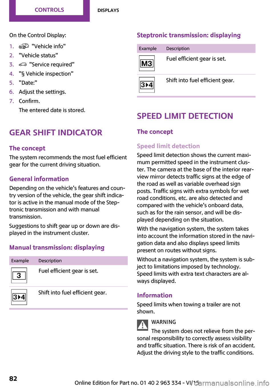
Gear shift indicator
The concept
The system recommends the most fuel efficient
gear for the current driving situation.
General information Depending on the vehicle's features and coun‐
try version of the vehicle, the gear shift indica‐
tor is active in the manual mode of the Step‐
tronic transmission and with manual
transmission.
Suggestions to shift gear up or down are dis‐
played in the instrument cluster.
Manual transmission: displaying
ExampleDescriptionFuel efficient gear is set.Shift into fuel efficient gear.Steptronic transmission: displayingExampleDescriptionFuel efficient gear is set.Shift into fuel efficient gear.
Speed limit detection
The concept
Speed limit detection
Speed limit detection shows the current maxi‐
mum permitted speed in the instrument clus‐
ter. The camera at the base of the interior rear‐
view mirror detects traffic signs at the edge of
the road as well as variable overhead sign
posts. Traffic signs with extra symbols for wet
road conditions, etc. are also detected and
compared with the vehicle's onboard data,
such as for the rain sensor, and will be dis‐
played depending on the situation.
With the navigation system, the system takes
into account the information stored in the navi‐
gation data and also displays speed limits
present on routes without signs.
Without a navigation system, the system is sub‐
ject to limitations imposed by technology.
Speed limits with extra text characters are al‐
ways displayed.
Information
Speed limits when towing a trailer are not
shown.
WARNING
The system does not relieve from the per‐
sonal responsibility to correctly assess visibility
and traffic situation. There is risk of an accident.
Adjust the driving style to the traffic conditions.
Seite 82CONTROLSDisplays82
Online Edition for Part no. 01 40 2 963 334 - VI/15
Page 83 of 246

Watch traffic closely and actively interfere in
the respective situations. ◀
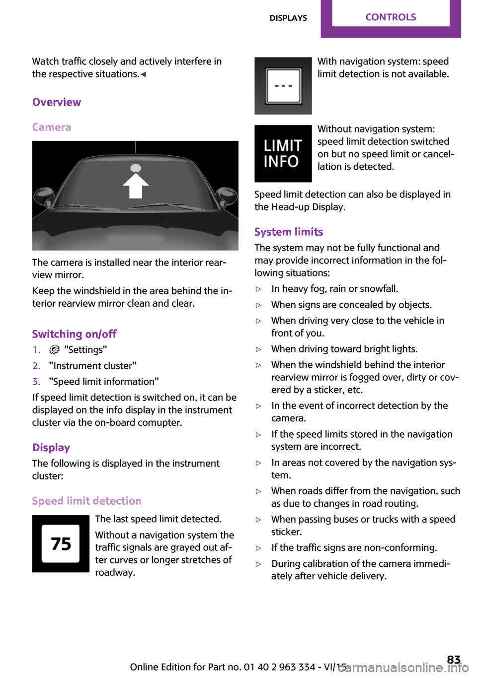
Overview
Camera
The camera is installed near the interior rear‐
view mirror.
Keep the windshield in the area behind the in‐
terior rearview mirror clean and clear.
Switching on/off
1. "Settings"2."Instrument cluster"3."Speed limit information"
If speed limit detection is switched on, it can be
displayed on the info display in the instrument
cluster via the on-board comupter.
Display The following is displayed in the instrument
cluster:
Speed limit detection The last speed limit detected.
Without a navigation system the
traffic signals are grayed out af‐
ter curves or longer stretches of
roadway.
With navigation system: speed
limit detection is not available.
Without navigation system:
speed limit detection switched
on but no speed limit or cancel‐
lation is detected.
Speed limit detection can also be displayed in
the Head-up Display.
System limits The system may not be fully functional and
may provide incorrect information in the fol‐
lowing situations:▷In heavy fog, rain or snowfall.▷When signs are concealed by objects.▷When driving very close to the vehicle in
front of you.▷When driving toward bright lights.▷When the windshield behind the interior
rearview mirror is fogged over, dirty or cov‐
ered by a sticker, etc.▷In the event of incorrect detection by the
camera.▷If the speed limits stored in the navigation
system are incorrect.▷In areas not covered by the navigation sys‐
tem.▷When roads differ from the navigation, such
as due to changes in road routing.▷When passing buses or trucks with a speed
sticker.▷If the traffic signs are non-conforming.▷During calibration of the camera immedi‐
ately after vehicle delivery.Seite 83DisplaysCONTROLS83
Online Edition for Part no. 01 40 2 963 334 - VI/15
Page 96 of 246

conditions, you should always switch on the
lights manually.
Daytime running lights
Position of switch:
, ,
The daytime running lights light up when the
ignition is switched on. After the ignition is
switched off, the parking lights light up in posi‐
tion
.
Activating/deactivating
In some countries, daytime running lights are
mandatory, so it may not be possible to deacti‐ vate the daytime running lights.
On the Control Display:
1. "Settings"2."Lighting"3."Daytime running lamps"
Settings are stored for the remote control cur‐
rently used.
Cornering lamp Position of switch:
When going around corners, the cornering light
also lights the interior area of the curve. Below
a speed of approx. 25 mph/40 km/h when the
turn signal is switched on and the steering an‐
gle is detected, there is automatic activation.
Malfunction A Check Control message is displayed.
Cornering light is disrupted or failed. Have the
system checked as soon as possible.
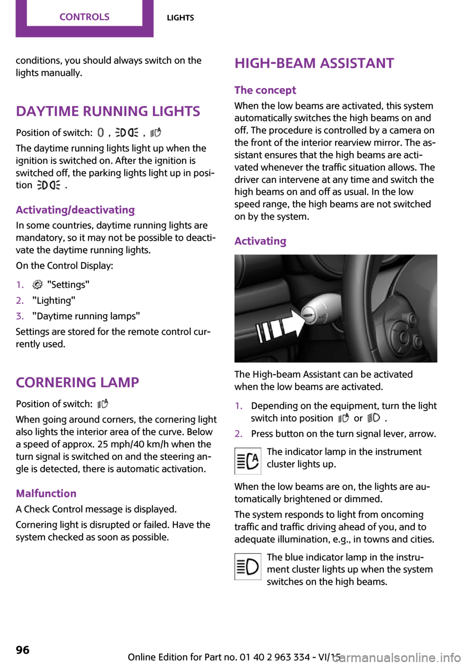
High-beam Assistant
The concept
When the low beams are activated, this system automatically switches the high beams on and
off. The procedure is controlled by a camera on
the front of the interior rearview mirror. The as‐
sistant ensures that the high beams are acti‐
vated whenever the traffic situation allows. The
driver can intervene at any time and switch the
high beams on and off as usual. In the low
speed range, the high beams are not switched
on by the system.
Activating
The High-beam Assistant can be activated
when the low beams are activated.
1.Depending on the equipment, turn the light
switch into position
or .
2.Press button on the turn signal lever, arrow.
The indicator lamp in the instrument
cluster lights up.
When the low beams are on, the lights are au‐
tomatically brightened or dimmed.
The system responds to light from oncoming
traffic and traffic driving ahead of you, and to
adequate illumination, e.g., in towns and cities.
The blue indicator lamp in the instru‐
ment cluster lights up when the system
switches on the high beams.
Seite 96CONTROLSLights96
Online Edition for Part no. 01 40 2 963 334 - VI/15