MINI Hardtop 4 Door 2016 Owner's Manual
Manufacturer: MINI, Model Year: 2016, Model line: Hardtop 4 Door, Model: MINI Hardtop 4 Door 2016Pages: 251, PDF Size: 6.71 MB
Page 121 of 251

Interior equipmentVehicle features and op‐
tions
This chapter describes all standard, country-
specific and optional features offered with the
series. It also describes features that are not
necessarily available in your car, e. g., due to
the selected options or country versions. This
also applies to safety-related functions and sys‐
tems. The respectively applicable country provi‐
sions must be observed when using the respec‐
tive features and systems.
Universal Integrated Re‐
mote Control
The concept
The Universal Integrated Remote Control can
operate up to 3 functions of remote-controlled
systems such as garage door drives or lighting
systems. The Universal Integrated Remote Con‐
trol replaces up to 3 different hand-held trans‐
mitters. To operate the remote control, the but‐
tons on the interior rearview mirror must be
programmed with the desired functions. The
hand-held transmitter for the particular system
is required in order to program the remote con‐
trol.
Before selling the vehicle, delete the stored
functions for the sake of security.
Information WARNING
Body parts can be jammed when operat‐
ing remote-controlled systems, e.g. the garage
door, using the universal garage door opener.
There is risk of injuries or risk of property dam‐
age. Make sure that the area of movement of
the respective system is clear during program‐ming and operation. Also follow the safety in‐
structions of the hand-held transmitter. ◀
Compatibility If this symbol is printed on the packag‐
ing or in the instructions of the system
to be controlled, the system is generally
compatible with the Universal Integrated Re‐
mote Control.
If you have any questions, please contact:▷A dealer’s service center or another quali‐
fied service center or repair shop.▷www.homelink.com on the Internet.
HomeLink is a registered trademark of Gentex
Corporation.
Overview
1LED2Programmable keys3Hand-held transmitters of the system
Programming
General information
1.Switch on the ignition.2.Initial setup:
Press and hold the left and right button on
the interior rearview mirror simultaneously
for approximately 20 seconds until the LEDSeite 121Interior equipmentCONTROLS121
Online Edition for Part no. 01 40 2 963 307 - VI/15
Page 122 of 251

on the interior rearview mirror flashes. This
erases all programming of the buttons on
the interior rearview mirror.3.Hold the hand-held transmitter for the sys‐
tem to be controlled approx. 1 to 3 in/2.5
to 8 cm away from the buttons of the inte‐
rior rearview mirror. The required distance
depends on the manual transmitter.4.Simultaneously press and hold the button
of the desired function on the hand-held
transmitter and the button to be program‐
med on the interior rearview mirror. The
LED on the interior rearview mirror will be‐
gin flashing slowly.5.Release both buttons as soon as the LED
flashes more rapidly. The LED flashing
faster indicates that the button on the inte‐
rior rearview mirror has been programmed.
If the LED does not flash faster after at least
60 seconds, change the distance between
the interior rearview mirror and the hand-
held transmitter and repeat the step. Sev‐
eral more attempts at different distances
may be necessary. Wait at least 15 seconds
between attempts.
Canada: if programming with the hand-
held transmitter was interrupted, hold
down the interior rearview mirror button
and repeatedly press and release the hand-
held transmitter button for 2 seconds.6.To program other functions on other but‐
tons, repeat steps 3 to 5.
The systems can be controlled using the interior
rearview mirror buttons.
Special feature of the alternating-code
wireless system
If you are unable to operate the system after
repeated programming, please check if the sys‐
tem to be controlled features an alternating-
code system.
Read the system's operating manual, or press
the programmed button on the interior rear‐
view mirror longer. If the LED on the interior
rearview mirror starts flashing rapidly and then
stays lit constantly for 2 seconds, the system
features an alternating-code system. Flashing
and continuous illumination of the LED will re‐
peat for approximately 20 seconds.
For systems with an alternating-code system,
the Universal Integrated Remote Control and
the system also have to be synchronized.
Please read the operating manual to find out
how to synchronize the system.
Synchronizing is easier with the aid of a second
person.
To synchronize:1.Park the vehicle within range of the re‐
mote-controlled system.2.Program the relevant button on the interior
rearview mirror as described.3.Locate and press the synchronizing button
on the system being programmed. You
have approx. 30 seconds for the next step.4.Hold down the programmed button on the
interior rearview mirror for approximately
3 seconds and then release it. If necessary,
repeat this step up to three times in order
to finish synchronization. Once synchroni‐
zation is complete, the programmed func‐
tion will be carried out.
Reprogramming individual buttons
1.Switch on the ignition.2.Press and hold the interior rearview mirror
button to be programmed.3.As soon as the interior rearview mirror LED
starts flashing slowly, hold the hand-held
transmitter for the system to be controlled
approx. 1 to 3 in/2.5 to 8 cm away from the
buttons of the interior rearview mirror. The
required distance depends on the manual
transmitter.Seite 122CONTROLSInterior equipment122
Online Edition for Part no. 01 40 2 963 307 - VI/15
Page 123 of 251

4.Likewise, press and hold the button of the
desired function on the hand-held trans‐
mitter.5.Release both buttons as soon as the interior
rearview mirror LED flashes more rapidly.
The LED flashing faster indicates that the
button on the interior rearview mirror has
been programmed. The system can then be
controlled by the button on the interior
rearview mirror.
If the LED does not flash faster after at least
60 seconds, change the distance and re‐
peat the step. Several more attempts at dif‐
ferent distances may be necessary. Wait at
least 15 seconds between attempts.
Canada: if programming with the hand-
held transmitter was interrupted, hold
down the interior rearview mirror button
and repeatedly press and release the hand-
held transmitter button for 2 seconds.
Controls
WARNING
Body parts can be jammed when operat‐
ing remote-controlled systems, e.g. the garage
door, using the universal garage door opener.
There is risk of injuries or risk of property dam‐
age. Make sure that the area of movement of
the respective system is clear during program‐
ming and operation. Also follow the safety in‐
structions of the hand-held transmitter. ◀
The system, such as the garage door, can be
operated using the button on the interior rear‐
view mirror while the engine is running or
when the ignition is started. To do this, hold
down the button within receiving range of the
system until the function is activated. The inte‐
rior rearview mirror LED stays lit while the wire‐
less signal is being transmitted.
Deleting stored functions
Press and hold the left and right button on the
interior rearview mirror simultaneously for ap‐
proximately 20 seconds until the LED flashes
rapidly. All stored functions are deleted. The
functions cannot be deleted individually.
Digital compass
Overview1Control button2Mirror display
Mirror display The point of the compass is displayed in the
mirror when driving straight.
Operating concept Various functions can be called up by pressing
the control button with a pointed object, such
as the tip of a ballpoint pen or similar object.
The following setting options are displayed in
succession, depending on how long the control
button is pressed:
▷Pressed briefly: turns display on/off.▷3 to 6 seconds: compass zone setting.▷6 to 9 seconds: compass calibration.▷9 to 12 seconds: left/right-hand steering
setting.▷12 to 15 seconds: language setting.
Setting the compass zones
Sets the particular compass zones on the vehi‐
cle so that the compass operates correctly; re‐
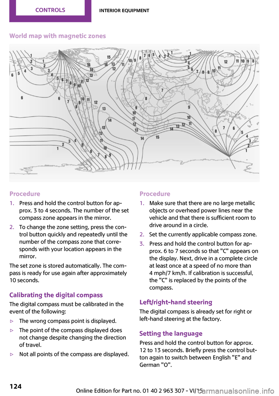
fer to World map with compass zones.
Seite 123Interior equipmentCONTROLS123
Online Edition for Part no. 01 40 2 963 307 - VI/15
Page 124 of 251

World map with magnetic zonesProcedure1.Press and hold the control button for ap‐
prox. 3 to 4 seconds. The number of the set
compass zone appears in the mirror.2.To change the zone setting, press the con‐
trol button quickly and repeatedly until the
number of the compass zone that corre‐
sponds with your location appears in the
mirror.
The set zone is stored automatically. The com‐
pass is ready for use again after approximately
10 seconds.
Calibrating the digital compass The digital compass must be calibrated in the
event of the following:
▷The wrong compass point is displayed.▷The point of the compass displayed does
not change despite changing the direction
of travel.▷Not all points of the compass are displayed.Procedure1.Make sure that there are no large metallic
objects or overhead power lines near the
vehicle and that there is sufficient room to
drive around in a circle.2.Set the currently applicable compass zone.3.Press and hold the control button for ap‐
prox. 6 to 7 seconds so that "C" appears on
the display. Next, drive in a complete circle
at least once at a speed of no more than
4 mph/7 km/h. If calibration is successful,
the "C" is replaced by the points of the
compass.
Left/right-hand steering
The digital compass is already set for right or
left-hand steering at the factory.
Setting the language
Press and hold the control button for approx.
12 to 13 seconds. Briefly press the control but‐ ton again to switch between English "E" and
German "O".
Seite 124CONTROLSInterior equipment124
Online Edition for Part no. 01 40 2 963 307 - VI/15
Page 125 of 251

Settings are stored automatically after approxi‐
mately 10 seconds.
Sun visor
Glare shield
Fold the sun visor down or up.
Vanity mirror
A vanity mirror is located in the sun visor be‐
hind a cover. When the cover is opened, the
mirror lighting switches on.
Ashtray/cigarette
lighter
Overview
The ashtray is located in one of the frontal cup
holders, the cigarette lighter above it in the
center console.
Ashtray In order to empty the ashtray, remove the ash‐
tray from the cupholder.
Lighter WARNING
Contact with hot heating elements or the
hot socket of the cigarette lighter can cause
burns. Flammable materials can ignite if the
cigarette lighter falls down or is held against
the respective objects. There is risk of fire and
injuries. Hold the cigarette lighter on its handle.
Make sure that children do not use the ciga‐
rette lighter and do not burn themselves, e.g.
by carrying the remote control along when ex‐
iting the vehicle. ◀
CAUTION
If metal objects fall into the socket, they
can cause a short circuit. There is risk of prop‐
erty damage. Replace the cigarette lighter or
socket cover again after using the socket. ◀
Push in the lighter.
The lighter can be removed as
soon as it pops back out.
Connecting electrical de‐ vices
Information CAUTION
Battery chargers for the vehicle battery
can work with high voltages and currents,
which means that the 12V on-board network
can be overloaded or damaged. There is risk of
property damage. Only connect battery charg‐
ers for the vehicle battery to the starting aid
terminals in the engine compartment. ◀
CAUTION
If metal objects fall into the socket, they
can cause a short circuit. There is risk of prop‐
erty damage. Replace the cigarette lighter or
socket cover again after using the socket. ◀
WARNING
Devices and cables in the unfolding area
of the airbags, e.g. portable navigation devices,
etc., can hinder the unfolding of the airbag or
be thrown around in the car's interior when un‐
folding. There is risk of injuries. make sure thatSeite 125Interior equipmentCONTROLS125
Online Edition for Part no. 01 40 2 963 307 - VI/15
Page 126 of 251

devices and cables are not in the airbag's area
of unfolding. ◀
Sockets Sockets can be used for the running electrical
devices with the engine running or with the ig‐
nition switched on. The total load of all sockets
must not exceed 140 watts at 12 volts.
Do not damage the socket by using non-com‐
patible connectors.
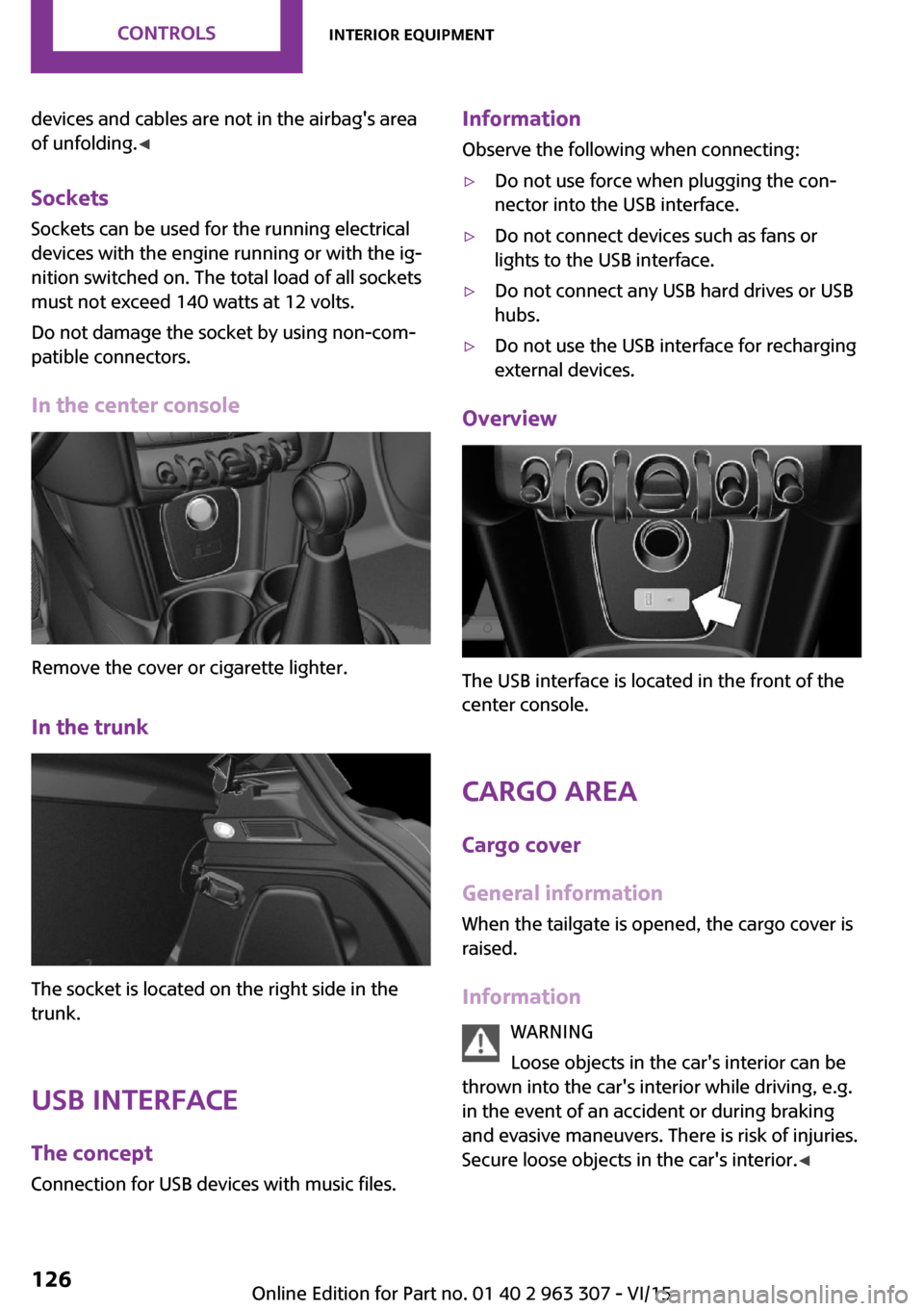
In the center console
Remove the cover or cigarette lighter.
In the trunk
The socket is located on the right side in the
trunk.
USB interface
The concept
Connection for USB devices with music files.
Information Observe the following when connecting:▷Do not use force when plugging the con‐
nector into the USB interface.▷Do not connect devices such as fans or
lights to the USB interface.▷Do not connect any USB hard drives or USB
hubs.▷Do not use the USB interface for recharging
external devices.
Overview
The USB interface is located in the front of the
center console.
Cargo area
Cargo cover
General information When the tailgate is opened, the cargo cover is
raised.
Information WARNING
Loose objects in the car's interior can be
thrown into the car's interior while driving, e.g.
in the event of an accident or during braking
and evasive maneuvers. There is risk of injuries.
Secure loose objects in the car's interior. ◀
Seite 126CONTROLSInterior equipment126
Online Edition for Part no. 01 40 2 963 307 - VI/15
Page 127 of 251

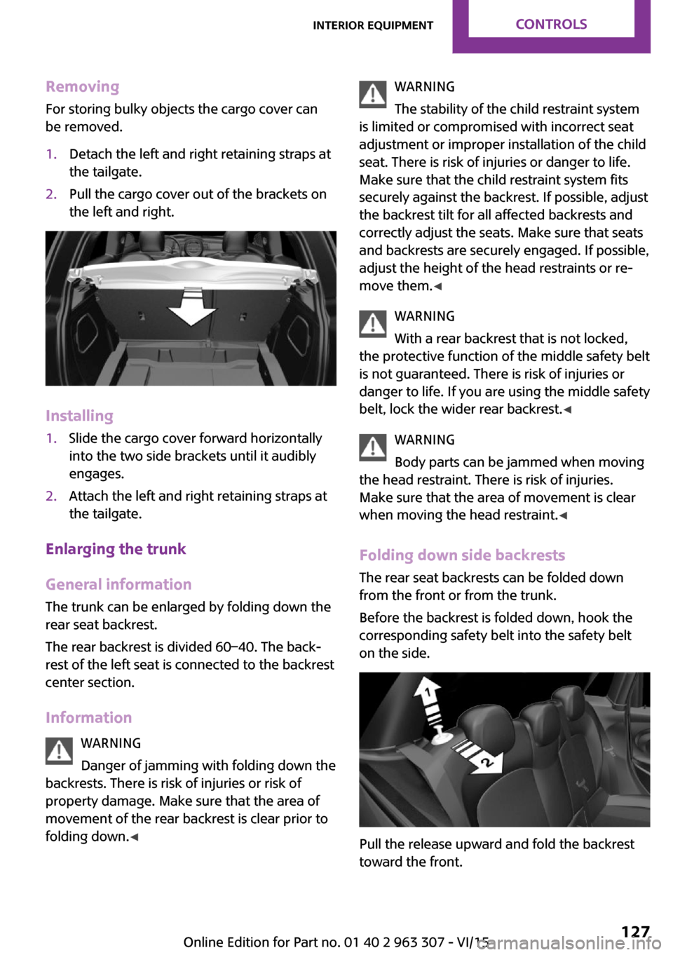
Removing
For storing bulky objects the cargo cover can be removed.1.Detach the left and right retaining straps at
the tailgate.2.Pull the cargo cover out of the brackets on
the left and right.
Installing
1.Slide the cargo cover forward horizontally
into the two side brackets until it audibly
engages.2.Attach the left and right retaining straps at
the tailgate.
Enlarging the trunk
General information
The trunk can be enlarged by folding down the
rear seat backrest.
The rear backrest is divided 60–40. The back‐
rest of the left seat is connected to the backrest
center section.
Information WARNING
Danger of jamming with folding down the
backrests. There is risk of injuries or risk of property damage. Make sure that the area of
movement of the rear backrest is clear prior to
folding down. ◀
WARNING
The stability of the child restraint system
is limited or compromised with incorrect seat
adjustment or improper installation of the child
seat. There is risk of injuries or danger to life.
Make sure that the child restraint system fits
securely against the backrest. If possible, adjust
the backrest tilt for all affected backrests and
correctly adjust the seats. Make sure that seats
and backrests are securely engaged. If possible,
adjust the height of the head restraints or re‐
move them. ◀
WARNING
With a rear backrest that is not locked,
the protective function of the middle safety belt
is not guaranteed. There is risk of injuries or
danger to life. If you are using the middle safety
belt, lock the wider rear backrest. ◀
WARNING
Body parts can be jammed when moving
the head restraint. There is risk of injuries.
Make sure that the area of movement is clear
when moving the head restraint. ◀
Folding down side backrests
The rear seat backrests can be folded down
from the front or from the trunk.
Before the backrest is folded down, hook the
corresponding safety belt into the safety belt
on the side.
Pull the release upward and fold the backrest
toward the front.
Seite 127Interior equipmentCONTROLS127
Online Edition for Part no. 01 40 2 963 307 - VI/15
Page 128 of 251

Folding back the backrestWARNING
With an unlocked backrest, an unsecured
load can be thrown into the car's interior, e.g.
in case of an accident, braking or evasive ma‐
neuver. There is risk of injuries. Make sure that
the backrest engages into the locking after
folding it back. ◀
Fold up the backrest and press it into the latch.
Make sure that the safety belt is not pinched.
Adjusting the backrest tilt WARNING
The stability of the child restraint system
is limited or compromised with incorrect seat
adjustment or improper installation of the child
seat. There is risk of injuries or danger to life.
Make sure that the child restraint system fits
securely against the backrest. If possible, adjust
the backrest tilt for all affected backrests and
correctly adjust the seats. Make sure that seats
and backrests are securely engaged. If possible,
adjust the height of the head restraints or re‐
move them. ◀
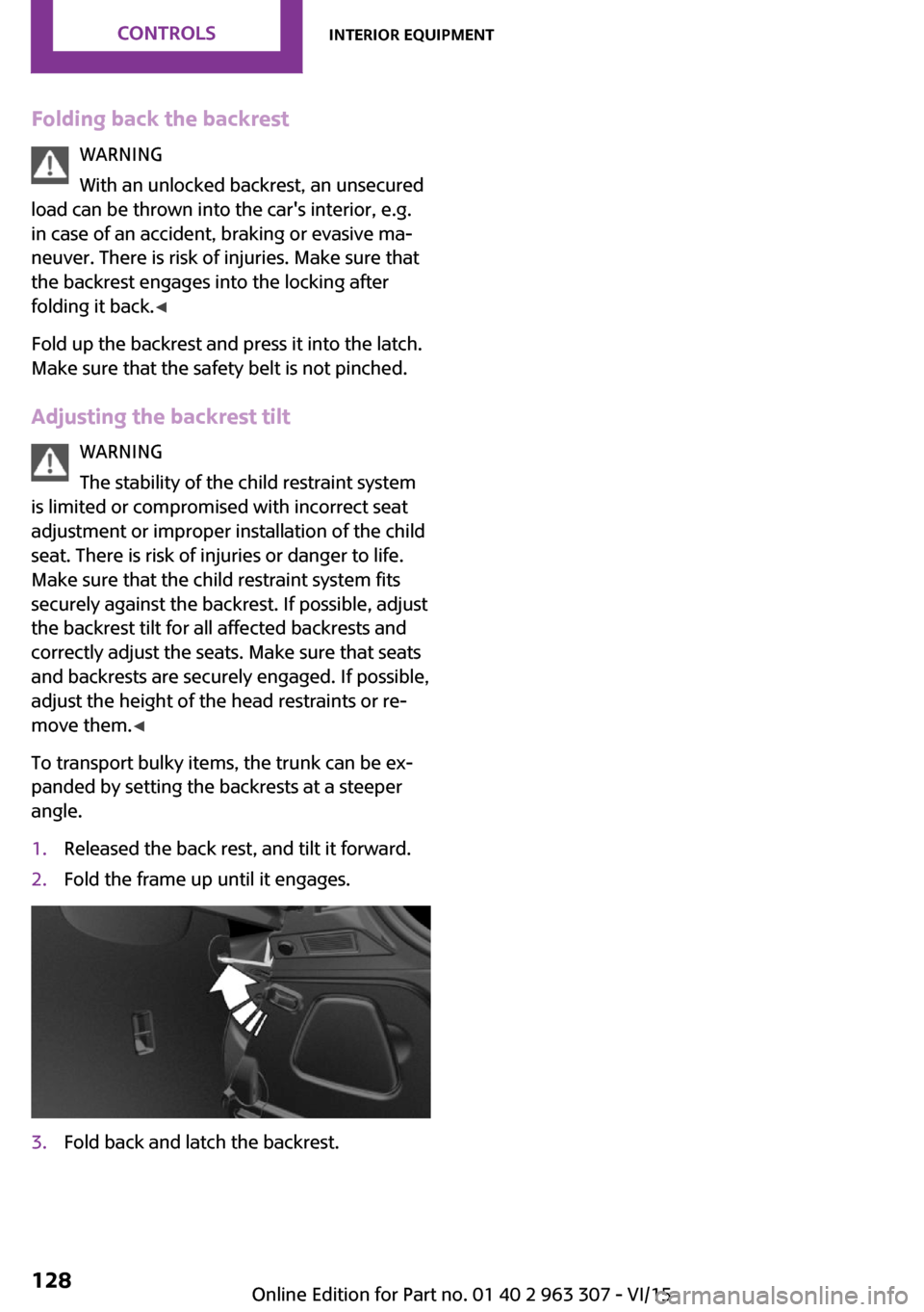
To transport bulky items, the trunk can be ex‐
panded by setting the backrests at a steeper
angle.1.Released the back rest, and tilt it forward.2.Fold the frame up until it engages.3.Fold back and latch the backrest.Seite 128CONTROLSInterior equipment128
Online Edition for Part no. 01 40 2 963 307 - VI/15
Page 129 of 251

Storage compartmentsVehicle features and op‐
tions
This chapter describes all standard, country-
specific and optional features offered with the
series. It also describes features that are not necessarily available in your car, e. g., due to
the selected options or country versions. This
also applies to safety-related functions and sys‐
tems. The respectively applicable country provi‐
sions must be observed when using the respec‐
tive features and systems.
Information WARNING
Loose objects in the car's interior can be
thrown into the car's interior while driving, e.g.
in the event of an accident or during braking
and evasive maneuvers. There is risk of injuries.
Secure loose objects in the car's interior. ◀
CAUTION
Anti-slip pads such as anti-slip mats can
damage the dashboard. There is risk of prop‐
erty damage. Do not use anti-slip pads. ◀
Overview
The following storage compartments are avail‐
able in the vehicle interior:▷Storage compartment in front of the cu‐
pholders.▷Storage tray in the center console.▷Glove compartment on the front passenger
side.▷Storage compartment in the center arm‐
rest.▷Compartments in the doors.▷Pockets on the backrests of the front seats.
Glove compartment
Information WARNING
Folded open, the glove compartment
protrudes in the car's interior. Objects in the
glove compartment can be thrown into the
car's interior while driving, e.g. in the event of
an accident or during braking and evasive ma‐
neuvers. There is risk of injuries. Always close
the glove compartment immediately after us‐
ing it. ◀
Opening
Pull the handle.
The light in the glove compartment switches
on.
Closing Fold up the cover.
Seite 129Storage compartmentsCONTROLS129
Online Edition for Part no. 01 40 2 963 307 - VI/15
Page 130 of 251

Compartments in the
doors
WARNING
Breakable object, e.g. glass bottle, can
break in the event of an accident. Broken glass
can be scattered in the car's interior. There is
risk of injuries. Do not stow any breakable ob‐
jects in the car's interior. ◀
Center armrest The center armrest contains a storage compart‐
ment.
Opening
Press button, arrow 1, and open center arm
rest upward, arrow 2.
Adjusting the height
Press button, arrow 1, and swing center arm
rest upward or downward into the desired
height, arrow 2.
Cupholders
Information WARNING
Unsuitable containers in the cup holder
and hot beverages can damage the cup holder
and increase the risk of injuries in the event of
an accident. There is risk of injuries or risk of
property damage. Use light-weight, unbreaka‐
ble, and sealable containers. Do not transport
hot beverages. Do not force objects into the
cup holder. ◀
Front
In the center console.
Rear
On 3-door models: in front of the rear seats and
in the and in the side armrests.
Seite 130CONTROLSStorage compartments130
Online Edition for Part no. 01 40 2 963 307 - VI/15