stop start MINI Hardtop 4 Door 2016 User Guide
[x] Cancel search | Manufacturer: MINI, Model Year: 2016, Model line: Hardtop 4 Door, Model: MINI Hardtop 4 Door 2016Pages: 251, PDF Size: 6.71 MB
Page 53 of 251

▷The vehicle battery charge is very low.▷Excessive cooling of the car's interior when
the heating is switched on.▷Manual transmission: low brake vacuum
pressure; this can occur, e.g., if the brake
pedal is depressed a number of times in
succession.
Switching the system on/off
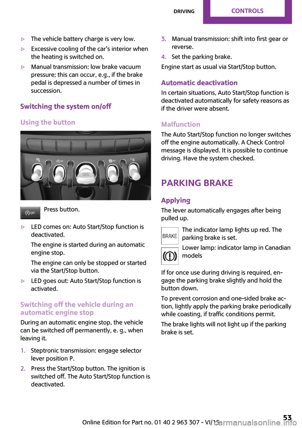
Using the button
Press button.
▷LED comes on: Auto Start/Stop function is
deactivated.
The engine is started during an automatic
engine stop.
The engine can only be stopped or started
via the Start/Stop button.▷LED goes out: Auto Start/Stop function is
activated.
Switching off the vehicle during an automatic engine stop
During an automatic engine stop, the vehicle
can be switched off permanently, e. g., when
leaving it.
1.Steptronic transmission: engage selector
lever position P.2.Press the Start/Stop button. The ignition is
switched off. The Auto Start/Stop function is
deactivated.3.Manual transmission: shift into first gear or
reverse.4.Set the parking brake.
Engine start as usual via Start/Stop button.
Automatic deactivation
In certain situations, Auto Start/Stop function is
deactivated automatically for safety reasons as
if the driver were absent.
MalfunctionThe Auto Start/Stop function no longer switches
off the engine automatically. A Check Control
message is displayed. It is possible to continue
driving. Have the system checked.
Parking brake ApplyingThe lever automatically engages after being
pulled up.
The indicator lamp lights up red. The
parking brake is set.
Lower lamp: indicator lamp in Canadian
models
If for once use during driving is required, en‐
gage the parking brake slightly and hold the
button down.
To prevent corrosion and one-sided brake ac‐
tion, lightly apply the parking brake periodically
while coasting, if traffic conditions permit.
The brake lights will not light up if the parking
brake is set.
Seite 53DrivingCONTROLS53
Online Edition for Part no. 01 40 2 963 307 - VI/15
Page 74 of 251

Setting the brightnessThe brightness can be adjusted when night
lighting is active in the instrument cluster.1. Press button.2. "Settings"3."Center Instrument"4."Brightness"5.Turn the right-hand knob.
Settings are stored for the profile currently
used.
Chrono package in the
cockpit
The concept
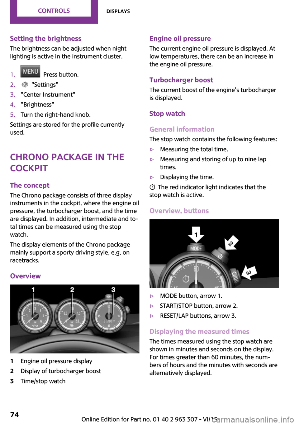
The Chrono package consists of three display
instruments in the cockpit, where the engine oil
pressure, the turbocharger boost, and the time
are displayed. In addition, intermediate and to‐
tal times can be measured using the stop
watch.
The display elements of the Chrono package
mainly support a sporty driving style, e,g, on
racetracks.
Overview
1Engine oil pressure display2Display of turbocharger boost3Time/stop watchEngine oil pressure
The current engine oil pressure is displayed. At
low temperatures, there can be an increase in
the engine oil pressure.
Turbocharger boostThe current boost of the engine's turbocharger
is displayed.
Stop watch
General information The stop watch contains the following features:▷Measuring the total time.▷Measuring and storing of up to nine lap
times.▷Displaying the time.
The red indicator light indicates that the
stop watch is active.
Overview, buttons
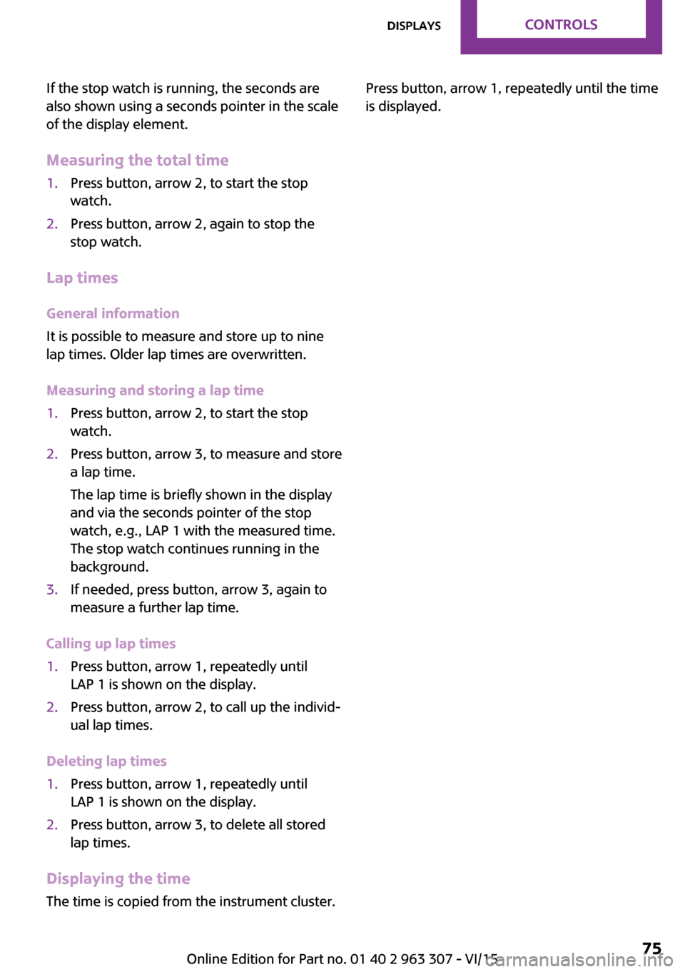
▷MODE button, arrow 1.▷START/STOP button, arrow 2.▷RESET/LAP buttons, arrow 3.
Displaying the measured times
The times measured using the stop watch are
shown in minutes and seconds on the display.
For times greater than 60 minutes, the num‐ bers of hours and the minutes with seconds are
alternatively displayed.
Seite 74CONTROLSDisplays74
Online Edition for Part no. 01 40 2 963 307 - VI/15
Page 75 of 251

If the stop watch is running, the seconds are
also shown using a seconds pointer in the scale
of the display element.
Measuring the total time1.Press button, arrow 2, to start the stop
watch.2.Press button, arrow 2, again to stop the
stop watch.
Lap times
General information
It is possible to measure and store up to nine
lap times. Older lap times are overwritten.
Measuring and storing a lap time
1.Press button, arrow 2, to start the stop
watch.2.Press button, arrow 3, to measure and store
a lap time.
The lap time is briefly shown in the display
and via the seconds pointer of the stop
watch, e.g., LAP 1 with the measured time.
The stop watch continues running in the
background.3.If needed, press button, arrow 3, again to
measure a further lap time.
Calling up lap times
1.Press button, arrow 1, repeatedly until
LAP 1 is shown on the display.2.Press button, arrow 2, to call up the individ‐
ual lap times.
Deleting lap times
1.Press button, arrow 1, repeatedly until
LAP 1 is shown on the display.2.Press button, arrow 3, to delete all stored
lap times.
Displaying the time
The time is copied from the instrument cluster.
Press button, arrow 1, repeatedly until the time
is displayed.Seite 75DisplaysCONTROLS75
Online Edition for Part no. 01 40 2 963 307 - VI/15
Page 85 of 251

Status displayThe current status of the Tire Pressure Monitor
TPM can be displayed, e.g., whether or not the
TPM is active.1. Press button.2. "Vehicle Info"3."Vehicle status"4."Tire Pressure Monitor (TPM)"
The status is displayed.
In addition, the current tire inflation pressures
are displayed. It shows the actual values read;
they may vary depending on driving style or
weather conditions.
Carry out reset
Reset the system after each adjustment of the
tire inflation pressure and after every tire or
wheel change.
1.Start the engine - do not drive off.2. Press button.3. "Vehicle Info"4."Vehicle status"5."Tire Pressure Monitor (TPM)"6.To reset the tire pressure: "Perform reset"7.Drive away.
"Resetting…" is displayed.
After driving faster than 19 mph/30 km/h for a
short period, the set tire inflation pressures are
accepted as reference values. The resetting
process is completed automatically while driv‐
ing.
You may interrupt this trip at any time. When
you continue the reset resumes automatically.
Low tire pressure message The yellow warning lamp lights up. A
Check Control message is displayed.
▷There is a flat tire or a major loss in tire in‐
flation pressure.▷A reset of the system was not carried out
after a wheel was changed. The system
therefore issues a warning based on the tire
pressures before the last reset.1.Reduce your speed and stop cautiously.
Avoid sudden braking and steering maneu‐
vers.2.Check whether the vehicle is fitted with
regular tires or run-flat tires.
Run-flat tires, refer to page 187, are la‐
beled with a circular symbol containing the
letters RSC marked on the tire's sidewall.
WARNING
A damaged regular tire with low or miss‐
ing tire inflation pressure impacts handling,
such as steering and braking response. Run-flat
tires can maintain limited stability. There is risk
of an accident. Do not continue driving if the
vehicle is not equipped with run-flat tires. Ob‐
serve the information on run-flat tires and con‐
tinued driving with these tires. ◀
A low tire inflation pressure might turn on DSC
Dynamic Stability Control.
Actions in the event of a flat tireNormal tires
1.Identify the damaged tire.
Do this by checking the air pressure in all
four tires.
The tire pressure gauge of the Mobility Sys‐
tem, refer to page 188, can be used for this
purpose.
If the tire inflation pressure in all four tires is
correct, the Tire Pressure Monitor may not
have been initialized. In this case, initialize
the system.
If identification of flat tire damage is not
possible, please contact a dealer’s serviceSeite 85SafetyCONTROLS85
Online Edition for Part no. 01 40 2 963 307 - VI/15
Page 87 of 251

ported though tire inflation pressures are cor‐
rect.
The tire inflation pressure depends on the tire's
temperature. Driving or exposure to the sun
will increase the tire's temperature, thus in‐
creasing the tire inflation pressure. The tire in‐
flation pressure is reduced when the tire tem‐
perature falls again. These circumstances may
cause a warning when temperatures fall very
sharply.
The system cannot indicate sudden serious tire
damage caused by external circumstances.
Malfunction The yellow warning lamp flashes and
then lights up continuously. A Check
Control message is displayed. No flat
tire or loss of tire pressure can be detected.
Examples and recommendations in the follow‐
ing situations:▷A wheel without TPM electronics is
mounted, e.g. emergency wheel: Have it
checked by a dealer’s service center or an‐
other qualified service center or repair shop
as needed.▷Malfunction: Have system checked by a
dealer’s service center or another qualified
service center or repair shop.▷TPM was unable to complete the reset. Re‐
set the system again.▷Interference through systems or devices
with the same radio frequency: After leav‐
ing the area of the interference, the system
automatically becomes active again.
Declaration according to NHTSA/FMVSS
138 Tire Pressure Monitoring System
Each tire, including the spare (if provided)
should be checked monthly when cold and in‐
flated to the inflation pressure recommended
by the vehicle manufacturer on the vehicle
placard or tire inflation pressure label. (If your
vehicle has tires of a different size than the size
indicated on the vehicle placard or tire inflation
pressure label, you should determine the
proper tire inflation pressure for those tires.) As
an added safety feature, your vehicle has been
equipped with a tire pressure monitoring sys‐
tem (TPMS) that illuminates a low tire pressure
telltale when one or more of your tires is signifi‐
cantly under-inflated. Accordingly, when the
low tire pressure telltale illuminates, you should
stop and check your tires as soon as possible,
and inflate them to the proper pressure. Driving
on a significantly under-inflated tire causes the
tire to overheat and can lead to tire failure. Un‐
der-inflation also reduces fuel efficiency and
tire tread life, and may affect the vehicle's han‐
dling and stopping ability. Please note that the
TPMS is not a substitute for proper tire mainte‐
nance, and it is the driver's responsibility to
maintain correct tire pressure, even if under-in‐
flation has not reached the level to trigger illu‐
mination of the TPMS low tire pressure telltale.
Your vehicle has also been equipped with a
TPMS malfunction indicator to indicate when
the system is not operating properly. The TPMS
malfunction indicator is combined with the low
tire pressure telltale. When the system detects
a malfunction, the telltale will flash for approxi‐
mately one minute and then remain continu‐
ously illuminated. This sequence will continue
upon subsequent vehicle start-ups as long as
the malfunction exists. When the malfunction
indicator is illuminated, the system may not be
able to detect or signal low tire pressure as in‐
tended. TPMS malfunctions may occur for a va‐
riety of reasons, including the installation of re‐
placement or alternate tires or wheels on the
vehicle that prevent the TPMS from functioning
properly. Always check the TPMS malfunction
telltale after replacing one or more tires or
wheels on your vehicle to ensure that the re‐
placement or alternate tires and wheels allow
the TPMS to continue to function properly.Seite 87SafetyCONTROLS87
Online Edition for Part no. 01 40 2 963 307 - VI/15
Page 88 of 251

FTM Flat Tire Monitor
The concept
The system does not measure the actual infla‐
tion pressure in the tires.
It detects a tire inflation pressure loss by com‐
paring the rotational speeds of the individual
wheels while moving.
In the event of a tire inflation pressure loss, the
diameter and therefore the rotational speed of
the corresponding wheel changes. This will be
detected and reported as a flat tire.
Functional requirements
The system must have been initialized when
the tire inflation pressure was correct; other‐
wise, reliable flagging of a flat tire is not as‐
sured. Initialize the system after each correc‐
tion of the tire inflation pressure and after
every tire or wheel change.
Status display The current status of the flat tire monitor can
be displayed, e.g., whether the RPA is active.1. Press button.2. "Vehicle Info"3."Vehicle status"4."Flat Tire Monitor (FTM)"
The status is displayed.
Initialization When initializing the once set inflation tire pres‐
sures serve as reference values in order to de‐
tect a flat tire. Initialization is started by con‐
firming the inflation pressures.
Do not initialize the system when driving with
snow chains.
1. Press button.2. "Vehicle Info"3."Vehicle status"4."Flat Tire Monitor (FTM)"5.Start the engine - do not drive off.6.Start the initialization with "Flat Tire
Monitor (FTM) reset".7.Drive away.
The initialization is completed while driving,
which can be interrupted at any time.
The initialization automatically continues when
driving resumes.
Indication of a flat tire The yellow warning lamp lights up. A
Check Control message is displayed.
There is a flat tire or a major loss in tire
inflation pressure.
1.Reduce your speed and stop cautiously.
Avoid sudden braking and steering maneu‐
vers.2.Check whether the vehicle is fitted with
normal tires or run-flat tires.
Run-flat tires, refer to page 187, are la‐
beled with a circular symbol containing the
letters RSC marked on the tire's sidewall.
WARNING
A damaged regular tire with low or miss‐
ing tire inflation pressure impacts handling,
such as steering and braking response. Run-flat
tires can maintain limited stability. There is risk
of an accident. Do not continue driving if the
vehicle is not equipped with run-flat tires. Ob‐
serve the information on run-flat tires and con‐
tinued driving with these tires. ◀
When a flat tire is indicated, DSC Dynamic Sta‐
bility Control is switched on if needed.
System limits A natural, even tire inflation pressure loss in all
four tires will not be recognized. Therefore,
check the tire inflation pressure regularly.
Seite 88CONTROLSSafety88
Online Edition for Part no. 01 40 2 963 307 - VI/15
Page 93 of 251

PrewarningThis warning is issued, e.g., when there is the
impending danger of a collision or the distance
to the vehicle ahead is too small.
The driver must intervene actively when there
is a prewarning.
Acute warning with braking function
Acute warning in displayed in case of the immi‐
nent danger of a collision when the vehicle ap‐
proaches another object at a relatively high dif‐
ferential speed.
The driver must intervene actively when there
is an acute warning. If necessary, the driver is
assisted by a minor automatic braking inter‐
vention in a possible risk of collision.
Acute warnings can also be triggered without
previous forewarning.
Braking intervention The warning prompts the driver himself/herself
to react. During a warning, the maximum brak‐
ing force is used. Premise for the brake booster
is sufficiently quick and sufficiently hard step‐
ping on the brake pedal. The system can assist
with some braking intervention if there is risk of
a collision. At low speeds vehicles may thus
come to a complete stop.
Manual transmission: During a braking inter‐
vention up to a complete stop, the engine may
be shut down.
The braking intervention is executed only if DSC
Dynamic Stability Control is switched on.
The braking intervention can be interrupted by
stepping on the accelerator pedal or by actively
moving the steering wheel.
Object detection can be restricted. Limitations
of the detection range and functional restric‐
tions are to be considered.System limits
Detection range The system's detection potential is limited.
Thus a system reaction might not come or
might come late.
E. g. the following situations may not be de‐ tected:▷Slow moving vehicles when you approach
them at high speed.▷Vehicles that suddenly swerve in front of
you, or sharply decelerating vehicles.▷Vehicles with an unusual rear appearance.▷Two-wheeled vehicles ahead of you.
Functional limitations
The system may not be fully functional in the
following situations:
▷In heavy fog, rain, sprayed water or snow‐
fall.▷In tight curves.▷If the field of view of the camera or the
front windshield are dirty or covered.▷If the driving stability control systems are
deactivated, e.g. DSC OFF.▷Up to 10 seconds after the start of the en‐
gine, via the Start/Stop button.▷During calibration of the camera immedi‐
ately after vehicle delivery.▷If there are constant blinding effects be‐
cause of oncoming light, e. g., from the sun
low in the sky.
Warning sensitivity
The more sensitive the warning settings are,
the more warnings are displayed. However,
there may also be an excess of false warnings.
Seite 93SafetyCONTROLS93
Online Edition for Part no. 01 40 2 963 307 - VI/15
Page 96 of 251

▷Pedestrians that are not detected as such
because of the viewing angle or contour.▷Pedestrians outside of the detection range.▷Pedestrians having a body size less than
32 in/80 cm.
Functional limitations
The system may not be fully functional or may
not be available in the following situations:
▷In heavy fog, rain, sprayed water or snow‐
fall.▷In tight curves.▷If the field of view of the camera or the
front windshield are dirty or covered.▷If the driving stability control systems are
deactivated, e.g. DSC OFF.▷Up to 10 seconds after the start of the en‐
gine, via the Start/Stop button.▷During calibration of the camera immedi‐
ately after vehicle delivery.▷If there are constant blinding effects be‐
cause of oncoming light, e. g., from the sun
low in the sky.▷When it is dark outside.
Brake force display
The concept
▷During normal brake application, the brake
lights light up.▷During heavy brake application, the flash‐
ers light up in addition.
PostCrash
In the event of an accident, the system can
bring the car to a halt automatically without in‐
tervention by the driver in certain situations.
This can reduce the risk of a further collision
and the consequences thereof.
Depressing the brake pedal can cause the vehi‐
cle to brake harder. This interrupts automatic
braking. Destepping on the gas pedal also in‐
terrupts automatic braking.
After coming to a halt, the brake is released au‐
tomatically. Secure the vehicle against rolling.
Seite 96CONTROLSSafety96
Online Edition for Part no. 01 40 2 963 307 - VI/15
Page 97 of 251

Driving stability control systemsVehicle features and op‐
tions
This chapter describes all standard, country-
specific and optional features offered with the
series. It also describes features that are not
necessarily available in your car, e. g., due to
the selected options or country versions. This
also applies to safety-related functions and sys‐
tems. The respectively applicable country provi‐
sions must be observed when using the respec‐
tive features and systems.
Anti-lock Braking System
ABS
ABS prevents locking of the wheels during
braking.
The vehicle contains its steering power even
during full brake applications, thus increasing
active safety.
ABS is operational every time you start the en‐
gine.
Brake assistant
When you apply the brakes rapidly, this system
automatically produces the greatest possible
braking force boost. It reduces the braking dis‐
tance to a minimum during emergency stop.
This system utilizes all of the benefits provided
by ABS.
Do not reduce the pressure on the brake pedal
for the duration of the emergency stop.DSC Dynamic Stability
Control
The concept
DSC prevents traction loss in the power wheels
when driving off and accelerating.
DSC also recognizes unstable vehicle conditions
such as fishtailing or nose-diving. Within the
physical limits DSC helps to keep the vehicle on
a steady course by reducing engine speed and
by applying brakes to the individual wheels.
Information Adapt your driving style to the situation, for an
appropriate driving style is always the responsi‐
bility of the driver.
The laws of physics cannot be repealed, not
even with DSC.
Therefore, do not reduce the additional safety
margin by driving in a risky manner.
WARNING
When driving with roof load, e.g. with
roof-mounted luggage rack, driving safety may
not be ensured in driving-critical situations due
to the elevated center of gravity. There is risk of
accidents or risk of property damage. Do not
deactivate Dynamic Stability Control DSC when
driving with roof load. ◀
Indicator/warning lights The indicator lamp flashes: DSC controls
the drive and braking forces.
The indicator lamp lights up: DSC has
failed.Seite 97Driving stability control systemsCONTROLS97
Online Edition for Part no. 01 40 2 963 307 - VI/15
Page 99 of 251

Dynamic Damping Con‐
trol
The concept
The tuning of the suspension can be changed
with the system.
Programs The system offers several different programs.
Select the programs via the Driving Dynamics
Control, refer to page 99.
MID/GREEN
Balanced tuning of the shock absorbers for
more comfort.
SPORTConsistently sporty tuning of the shock absorb‐
ers for greater driving agility.
Driving Dynamics Con‐
trol
The concept The Driving Dynamics Control helps to fine-
tune the vehicle's settings and features. Choose
between three different programs. Driving Dy‐
namics Control will activate the particular pro‐
gram.
Operating the programsDriving Dynamics ControlProgramMID
GREEN
SPORT
MID For balanced tuning.
With each starting operation, MID is activated
using the Start/Stop button.
GREEN GREEN, refer to page 143, provides consistent
tuning to maximize range.
Activating GREEN
Turn Driving Dynamics Control to the right until
GREEN is displayed in the instrument cluster.
Configuring GREEN
Via the Driving Dynamics Control1.Activate GREEN.2."Configure GREEN"3.Configure the program.
Via radio
1. Press button.2. "Settings"3."Driving mode"4."Configure GREEN"5.Configure the program.
For vehicles without a configurable SPORT pro‐
gram:
1. Press button.2. "Settings"3."GREEN Mode"4.Configure the program.
This configuration is retrieved when GREEN is
activated.
SPORT
Consistently sporty tuning of the engine control
for greater driving agility.
With the appropriate equipment, the tuning of
the suspension also changes and SPORT can be
individually configured.
Seite 99Driving stability control systemsCONTROLS99
Online Edition for Part no. 01 40 2 963 307 - VI/15