MINI Hardtop 4 Door 2016 Owner's Manual
Manufacturer: MINI, Model Year: 2016, Model line: Hardtop 4 Door, Model: MINI Hardtop 4 Door 2016Pages: 251, PDF Size: 6.71 MB
Page 201 of 251

Socket for OBD Onboard
Diagnosis
Information CAUTION
Improper use of the socket for Onboard
Diagnosis can lead to vehicle malfunctions.
There is risk of property damage. The manufac‐
turer of your vehicle strongly recommends ac‐
cess to the socket for Onboard Diagnosis be
limited to a dealer's service center, another
qualified service center or repair shop or other
authorized persons. ◀
Position
There is an OBD socket on the driver's side for
checking the primary components in the vehi‐
cle's emissions.
Emissions
▷The warning lamp lights up:
Emissions are deteriorating. Have
the vehicle checked as soon as pos‐
sible.▷The warning lamp flashes under certain cir‐
cumstances:
This indicates that there is excessive misfir‐
ing in the engine.
Reduce the vehicle speed and have the sys‐
tem checked immediately; otherwise, seri‐
ous engine misfiring within a brief period
can seriously damage emission controlcomponents, in particular the catalytic con‐
verter.Seite 201MaintenanceMOBILITY201
Online Edition for Part no. 01 40 2 963 307 - VI/15
Page 202 of 251

Replacing componentsVehicle features and op‐
tions
This chapter describes all standard, country-
specific and optional features offered with the
series. It also describes features that are not
necessarily available in your car, e. g., due to
the selected options or country versions. This
also applies to safety-related functions and sys‐
tems. The respectively applicable country provi‐
sions must be observed when using the respec‐
tive features and systems.
Onboard vehicle tool kit
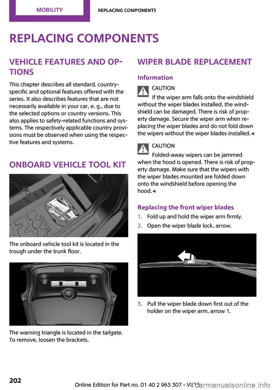
The onboard vehicle tool kit is located in the
trough under the trunk floor.
The warning triangle is located in the tailgate.
To remove, loosen the brackets.
Wiper blade replacement
Information CAUTION
If the wiper arm falls onto the windshield
without the wiper blades installed, the wind‐
shield can be damaged. There is risk of prop‐
erty damage. Secure the wiper arm when re‐
placing the wiper blades and do not fold down
the wipers without the wiper blades installed. ◀
CAUTION
Folded-away wipers can be jammed
when the hood is opened. There is risk of prop‐
erty damage. Make sure that the wipers with
the wiper blades mounted are folded down
onto the windshield before opening the
hood. ◀
Replacing the front wiper blades1.Fold up and hold the wiper arm firmly.2.Open the wiper blade lock, arrow.3.Pull the wiper blade down first out of the
holder on the wiper arm, arrow 1.Seite 202MOBILITYReplacing components202
Online Edition for Part no. 01 40 2 963 307 - VI/15
Page 203 of 251

Then pull the wiper blade free from the
holder of the wiper arm, arrow 2.4.Insert and latch a new wiper blade in re‐
verse order.5.Fold down the wipers.
Replace rear wiper blade
1.Fold up and hold the wiper arm firmly.2.Turn the wiper blade all the way back.3.Continue turning the wiper blade all the
way so that it pops out of the holder.4.Press the new wiper blade into the holder
until you hear it snap into place.5.Fold the wipers in.
Lamp and bulb replace‐
ment
General information Lights and bulbs make an essential contribution
to vehicle safety.
The manufacturer of the vehicle recommends
that you have appropriate work performed by a
dealer’s service center or another qualified
service center or repair shop if you are unfami‐
liar with it or if it has not been described here.
A spare lamp box is available from a dealer’s
service center or another qualified service cen‐
ter or repair shop.
Information
Lights and bulbs WARNING
Bulbs can get hot during operation. Con‐
tact with the bulbs can cause burns. There is
risk of injuries. Only change bulbs after they
have cooled off. ◀
WARNING
Work on switched-on lighting systems
can cause short circuits. There is risk of injuries
or risk of property damage. When working on
the lighting system, switch off the lamps in
question. If necessary, heed the bulb manufac‐
turer's instructions. ◀
CAUTION
Contaminated bulbs reduce their service
life. There is risk of property damage. Do not
hold new bulbs with your bare hands. Use a
clean cloth or something similar, or hold the
bulb by its base. ◀
Light-emitting diodes (LEDs)
Some items of equipment use light-emitting di‐
odes installed behind a cover as a light source.
These light-emitting diodes, which are related
to conventional lasers, are officially designated
as Class 1 light-emitting diodes.
WARNING
Too intensive brightness can irritate or
damage the retina of the eye. There is risk of
injuries. Do not look directly into the headlights
or other light sources for an extended period of
time. Do not remove the LED covers. ◀Seite 203Replacing componentsMOBILITY203
Online Edition for Part no. 01 40 2 963 307 - VI/15
Page 204 of 251

Headlight glass
Condensation can form on the inside of the ex‐
ternal lights in cool or humid weather. When
driving with the lights switched on, the conden‐
sation evaporates after a short time. The head‐
light glass does not need to be changed.
If despite driving with the lights switched on,
increasing humidity forms, e. g. water droplets
in the lamp, the manufacturer of your vehicle
recommends having it checked by a dealer’s
service center or another qualified service cen‐
ter or repair shop.
Front lights, bulb replacement
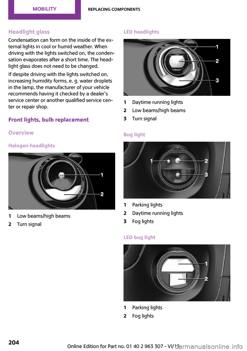
Overview Halogen headlights1Low beams/high beams2Turn signalLED headlights1Daytime running lights2Low beams/high beams3Turn signal
Bug light
1Parking lights2Daytime running lights3Fog lights
LED bug light
1Parking lights2Fog lightsSeite 204MOBILITYReplacing components204
Online Edition for Part no. 01 40 2 963 307 - VI/15
Page 205 of 251

LED low beams/LED high beamsFollow the general instructions on lights and
bulbs, refer to page 203.
The lights feature LED technology. Contact a
dealer’s service center or another qualified
service center or repair shop in the event of a
malfunction.
Halogen low beams/halogen high
beams
Follow the general instructions on lights and
bulbs, refer to page 203.
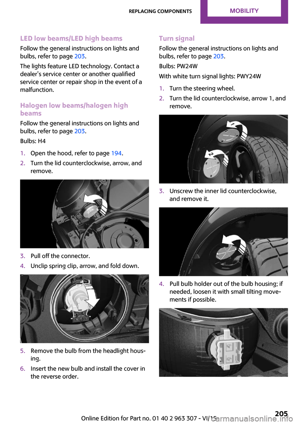
Bulbs: H41.Open the hood, refer to page 194.2.Turn the lid counterclockwise, arrow, and
remove.3.Pull off the connector.4.Unclip spring clip, arrow, and fold down.5.Remove the bulb from the headlight hous‐
ing.6.Insert the new bulb and install the cover in
the reverse order.Turn signal
Follow the general instructions on lights and
bulbs, refer to page 203.
Bulbs: PW24W
With white turn signal lights: PWY24W1.Turn the steering wheel.2.Turn the lid counterclockwise, arrow 1, and
remove.3.Unscrew the inner lid counterclockwise,
and remove it.4.Pull bulb holder out of the bulb housing; if
needed, loosen it with small tilting move‐
ments if possible.Seite 205Replacing componentsMOBILITY205
Online Edition for Part no. 01 40 2 963 307 - VI/15
Page 206 of 251

5.Pull the bulb out of the fixture.6.Insert the new bulb and install the cover in
the reverse order.
LED parking lights/LED fog lights
Follow the general instructions on lights and
bulbs, refer to page 203.
The lights feature LED technology. Contact a
dealer’s service center or another qualified
service center or repair shop in the event of a
malfunction.
Parking lights/fog lights/daytime
running lights
Follow the general instructions on lights and
bulbs, refer to page 203.
Bulbs:
▷Parking lights for halogen headlights: W5W
Parking lights for LED headlights: W5W NBV▷Daytime running light: PSX24W▷Fog lamp: H8
Replacing the bulbs
1.Turn the steering wheel.2.Turn the lid counterclockwise, arrow 2, and
remove.3.Remove the corresponding connector.4.Remove the bulb holder.▷Turn the parking light bulb holder coun‐
ter-clockwise, arrow 1, and remove.▷Press together the upper and lower
locking of the daytime running lightsbulb holder, arrow 2, and remove the
bulb holder.
For better accessibility, if needed, re‐
move the bulb of the fog lamp before‐
hand.▷Turn the fog light bulb holder counter-
clockwise, arrow 3, and remove.5.Pull the bulb out of the fixture.6.Insert the new bulb and install the cover in
the reverse order.
The daytime running lights bulb holder en‐
gages audibly, first below, then above.
Tail lights, bulb replacement
Overview
Vehicles with a rear fog lamp
1Side tail lights2Rear fog lamp3License plate lamp4Center brake lampSeite 206MOBILITYReplacing components206
Online Edition for Part no. 01 40 2 963 307 - VI/15
Page 207 of 251

Vehicle with two rear fog lights1Side tail lights2Rear fog lights3License plate lamp4Center brake lamp
Side tail lights
1Brake lights/tail lights2Turn signal3Reversing lights
Side LED tail lights
1Tail lights2Turn signal3Brake light4Reversing lights
Side tail lights
Follow the general instructions on lights and
bulbs, refer to page 203.
Bulbs: P21W
1.Open tailgate, refer to page 27.2.Remove left or right cover.3.Through the opening, loosen the plug con‐
nector, arrow 2 on the bulb holder.
Press the latches together, arrows 1, and
remove the bulb holder.4.Remove the bulb holder from the opening.5.Press the nonworking bulb gently into the
socket, turn counterclockwise and remove.▷Arrow 1: brake lights/tail lights▷Arrow 2: turn signalSeite 207Replacing componentsMOBILITY207
Online Edition for Part no. 01 40 2 963 307 - VI/15
Page 208 of 251

▷Arrow 3: reversing light6.Proceed in the reverse order to insert the
new bulb and attach the bulb holder. Make
sure that the bulb holder engages in all fas‐
teners.
Central brake lamp and license plate
lamp
Follow the general instructions on lights and
bulbs, refer to page 203.
The lights feature LED technology. Contact a
dealer’s service center or another qualified
service center or repair shop in the event of a
malfunction.
Vehicles with a rear fog lamp Follow the general instructions on Lights and
bulbs, refer to page 203.
Bulbs: W16W
1.On vehicles with heat shield:
Loosen 3 screws, arrow.2.Push the heat shield forward and the
bumper back in order to be able to reach
the fog lamp.3.Turn the bulb socket counterclockwise and
remove.
The wire is long enough to guide the socket
down and through between any heat shield
that may be installed and the bumper.4.Replace nonworking bulb.5.To install the new bulb, proceed in reverse
order of removal.
Vehicle with two rear fog lights
Follow the general instructions on Lights and
bulbs, refer to page 203.
Bulbs: W16W
Left rear fog lamp:
1.On vehicles with heat shield:
Loosen 3 screws, arrow.2.Push the heat shield forward and the
bumper back in order to be able to reach
the fog lamp.3.Turn the bulb socket counterclockwise and
remove.Seite 208MOBILITYReplacing components208
Online Edition for Part no. 01 40 2 963 307 - VI/15
Page 209 of 251

The wire is long enough to guide the socket
down and through between any heat shield
that may be installed and the bumper.4.Replace nonworking bulb.5.To install the new bulb, proceed in reverse
order of removal.
Right fog lamp:
1.Turn the bulb socket counterclockwise and
remove.
The wire is long enough to guide the socket
down and through between any heat shield
that may be installed and the bumper.2.Replace nonworking bulb.3.To install the new bulb, proceed in reverse
order of removal.
Side turn signal, bulb replacement
Follow the general instructions on lights and
bulbs, refer to page 203.
Bulbs:
▷With orange lens: W5W▷With white lens: WY5W diadem1.Open the hood. The covers of the side turn
signal lights are on the left and right next to
the hinges of the hood.2.Loosen nuts of the cover by hand and re‐
move the cover.3.Turn the bulb holder counterclockwise and
remove.4.Replace the bulb.5.To insert the new bulb, proceed in reverse
order of removal. Insert the nuts of the
cover and press down.Seite 209Replacing componentsMOBILITY209
Online Edition for Part no. 01 40 2 963 307 - VI/15
Page 210 of 251

Changing wheelsInformation
When using run-flat tires or tire sealants, a tire
does not need to be changed immediately in
the event of pressure loss due to a flat tire.
Which is why no spare tire is available.
The tools for changing wheels are available as
accessories from your dealer’s service center or
another qualified service center or repair shop.
Jacking points for the vehicle jack
The jacking points for the vehicle jack are lo‐
cated at the positions shown.
Emergency wheel
Safety measures
▷Park the vehicle as far away as possible
from passing traffic and on solid ground.
Switch on the hazard warning system.▷Set the parking brake and engage lever in
position P P.▷Have all vehicle occupants get out of the
vehicle and ensure that they remain out‐
side the immediate area in a safe place,
such as behind a guardrail.▷If necessary, set up a warning triangle or
portable hazard warning lamp at an appro‐
priate distance.▷Perform wheel change only on a flat, solid
and slip-resistant surface. On soft or slip‐
pery ground, e.g., snow, ice, tiles, etc., thevehicle or vehicle jack can slip away to the
side.▷Do not place wood blocks or similar items
under the vehicle jack; otherwise, it cannot
reach its carrying capacity because of the
restricted height.▷If the vehicle is raised, do not lie under the
vehicle and do not start the engine; other‐
wise, a fatal hazard exists.
Information
WARNING
The vehicle jack is optimized for lifting
the vehicle and for the jacking points on the ve‐
hicle only. There is risk of injuries. Do not lift
any other vehicle or cargo using the vehicle
jack. ◀
Removing the emergency wheel The emergency wheel is housed in a well on
the underbody of the vehicle. The screw con‐
nection of the emergency wheel is in the cargo
area underneath the floor mat, on the floor of
the storage compartment for the onboard vehi‐
cle tool kit.
1.Loosen the nut using the wheel wrench
from the onboard vehicle tool kit.2.Remove the retaining plate.Seite 210MOBILITYReplacing components210
Online Edition for Part no. 01 40 2 963 307 - VI/15