deactivate MINI Paceman 2013 Owner's Manual
[x] Cancel search | Manufacturer: MINI, Model Year: 2013, Model line: Paceman, Model: MINI Paceman 2013Pages: 275, PDF Size: 4.23 MB
Page 19 of 275
AT A GLANCEOnboard computer
18
Changing between panels
After selecting a menu item, e.g. "Radio", a new
menu is displayed on a panel. The panels can
overlap.
>Move the MINI joystick to the left.
Current panel is closed and the previous
panel is displayed.
> Move the MINI joystick to the right.
The new panel is opened and placed on top.
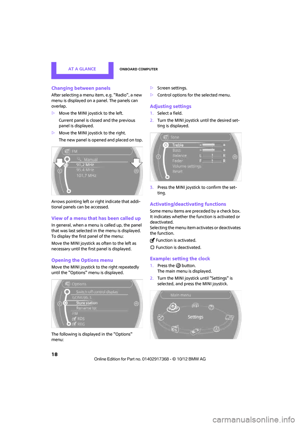
Arrows pointing left or right indicate that addi-
tional panels can be accessed.
View of a menu that has been called up
In general, when a menu is called up, the panel
that was last selected in the menu is displayed.
To display the first panel of the menu:
Move the MINI joystick as often to the left as
necessary until the firs t panel is displayed.
Opening the Options menu
Move the MINI joystick to the right repeatedly
until the "Options" menu is displayed.
The following is displayed in the "Options"
menu: >
Screen settings.
> Control options for the selected menu.
Adjusting settings
1.Select a field.
2. Turn the MINI joystick until the desired set-
ting is displayed.
3. Press the MINI joystick to confirm the set-
ting.
Activating/deactivating functions
Some menu items are preceded by a check box.
It indicates whether the function is activated or
deactivated.
Selecting the menu item activates or deactivates
the function.
Function is activated.
Function is deactivated.
Example: setting the clock
1. Press the button.
The main menu is displayed.
2. Turn the MINI joystick until "Settings" is
selected, and press the MINI joystick.
00320051004F004C00510048000300280047004C0057004C005200510003
Page 28 of 275
Opening and closingCONTROLS
27
Personal Profile settings
For more information on specific settings, refer
to the specified pages.
> Response of the central locking system
when the car is being unlocked 27
> Automatic locking of the vehicle 30
> Triple turn signal activation 55
> Settings for the displays on the onboard
computer, in the speedometer and in the
tachometer:
>12 h/24 h mode of the clock 66
> Date format 67
> Brightness of the Control Display 70
> Language on the Control Display 69
> Units of measure for fuel consumption,
distance covered/re maining distances
and temperature 64
> Light settings:
>Pathway lighting 85
> Daytime running lights 85
> Automatic climate control: activating/deac-
tivating the AUTO program, setting the tem-
perature, air volume and air distribution 90
> Entertainment:
>Audio volume 141
> Tone control 141
Central lock ing system
The concept
The central locking system is ready for operation
whenever the driver's door is closed.
The system simultaneously engages and
releases the locks on the following:
>Doors
> Tailgate
> Fuel filler flap
Operating from outside
>Via the remote control
> Using the door lock
> In cars with Comfor t Access, via the door
handles on the driver's and passenger's
sides
The anti-theft system is also operated at the
same time. It prevents the doors from being
unlocked using the lock buttons or door han-
dles. The remote control can also be used to
switch the welcome lamps, the interior light, and
the ambient lighting on and off. The alarm sys-
tem
is also activated or deactivated, page 32.
Operating from inside
Switch/button for central locking system,
page30.
In the event of a sufficiently severe accident, the
central locking system unlocks automatically. In
addition, the hazard warning flashers and inte-
rior lamps come on.
Opening and closing:
from outside
Persons or animals in a parked vehicle
could lock the doors from the inside. Take
the key with you when you leave the vehicle so
that the vehicle can be opened from the out-
side. <
Using the remote control
Unlocking
Press the button.
The welcome lamps and interior lamps come on.
Unlocking mode
You can also set which parts of the car are
unlocked. The setting is stored for the remote
control in use.
00320051004F004C00510048000300280047004C0057004C005200510003
Page 47 of 275

CONTROLSTransporting children safely
46
Transporting children safely
Vehicle equipment
In this chapter, all production, country, and
optional equipment that is offered in the model
range is described. Equipment is also described
that is not available because of, for example,
selected options or coun try version. This also
applies to safety relate d functions and systems.
The right place for
children
Do not leave children unattended in the
vehicle; otherwise, they could endanger
themselves and/or other persons by opening the
doors, for example. <
Children should always sit in the rear
Accident research has shown that the safest
place for children is on the rear seat.
Only transport children under the age of
13 or smaller than 5 ft/150 cm in the rear
in a child restraint system suitable for their age,
weight and size. Otherwise, there is an
increased risk of injury in the event of an acci-
dent. <
Children 13 years of age or older must be buck-
led in with a safety belt as soon as there no
longer is any child restraint system that is appro-
priate for their age, size and weight.
Exception for front passenger seat
Front passenger airbags
Should it be necessary to use a child
restraint system on the front passenger
seat, the front and side airbags must be deacti-
vated. Otherwise, there is an increased risk of
injury to the child if th e airbags deploy, even if
the child is seated in a child restraint system.< For more information on
automatic deactivation
of the front passenger airbags, refer to page 82.
Child restraint systems,
installation
Before installing a child restraint system on the
rear seats, move the seat as far back as possible.
5-seater: adjust the inclination of the center
backrest to the respective outer backrest.
After the child restr aint system has been
installed on the respecti ve rear seat, move the
backrest forward so that the it rests lightly
against the child restrain t system, refer to Rear
seat backrests on page 107.
Observe the child restraint system manu-
facturer's instructions when selecting,
installing and using child restraint systems. Oth-
erwise, the protective effect may be dimin-
ished. <
On the front passenger seat
After installing a chil d restraint system on
the front passenger se at, make sure that
the front, side, and knee airbags for the front
passenger are deactivated; otherwise, there is
an increased risk of inju ry if the airbags deploy.<
Seat position
Before installing a child restraint system, move
the front passenger seat as far back and up as
possible to obtain the be st possible position for
the belt. Do not change the seat position after
this.
00320051004F004C00510048000300280047004C0057004C005200510003
Page 55 of 275
CONTROLSDriving
54
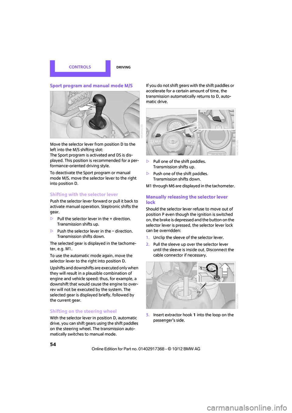
Sport program and manual mode M/S
Move the selector lever from position D to the
left into the M/S shifting slot:
The Sport program is activated and DS is dis-
played. This position is recommended for a per-
formance-oriented driving style.
To deactivate the Sport program or manual
mode M/S, move the selector lever to the right
into position D.
Shifting with the selector lever
Push the selector lever forward or pull it back to
activate manual operation. Steptronic shifts the
gear.
> Pull the selector lever in the + direction.
Transmission shifts up.
> Push the selector leve r in the – direction.
Transmission shifts down.
The selected gear is displayed in the tachome-
ter, e.g. M1.
To use the automatic mode again, move the
selector lever to the right into position D.
Upshifts and downshifts are executed only when
they will result in a plausible combination of
engine and vehicle speed; thus, for example, a
downshift that would cause the engine to over-
rev will not be executed by the system. The
selected gear is displayed briefly, followed by
the current gear.
Shifting on the steering wheel
With the selector lever in position D, automatic
drive, you can shift gears using the shift paddles
on the steering wheel. The transmission auto-
matically switches to manual mode. If you do not shift gears with the shift paddles or
accelerate for a certai
n amount of time, the
transmission automatically returns to D, auto-
matic drive.
> Pull one of the shift paddles.
Transmission shifts up.
> Push one of the shift paddles.
Transmission shifts down.
M1 through M6 are displayed in the tachometer.
Manually releasing the selector lever
lock
Should the selector lever refuse to move out of
position P even though the ignition is switched
on, the brake is depressed and the button on the
selector lever is pressed, the selector lever lock
can be overridden:
1. Unclip the sleeve of the selector lever.
2. Pull the sleeve up over the selector lever
until the sleeve is insi de out. Disconnect the
cable connector if necessary.
3. Insert extractor hook 1 into the loop on the
passenger's side.
00320051004F004C00510048000300280047004C0057004C005200510003
Page 57 of 275
CONTROLSDriving
56
Switching on wipers
Press the lever upward, arrow1.
The lever automatically returns to its initial posi-
tion when released.
Normal wiper speed
Press once.
The system switches to intermittent operation
when the vehicle is stationary.
Fast wiper speed
Press twice or press beyond the resistance point.
The system switches to normal speed when the
vehicle is stationary.
Intermittent wipe or rain sensor
If the car is not equipped with a rain sensor, the
intermittent-wipe time is preset.
If the car is equipped with a rain sensor, the time
between wipes is contro lled automatically and
depends on the intensity of the rainfall. The rain
sensor is mounted on the windshield, directly in
front of the interior rearview mirror.
Activating intermittent wipe or rain
sensor
Press button, arrow 3.
This symbol is displayed in the
tachometer.
Deactivate the rain se nsor before entering
an automatic car wash . Failure to do so
could result in damage caused by undesired
wiper activation. <
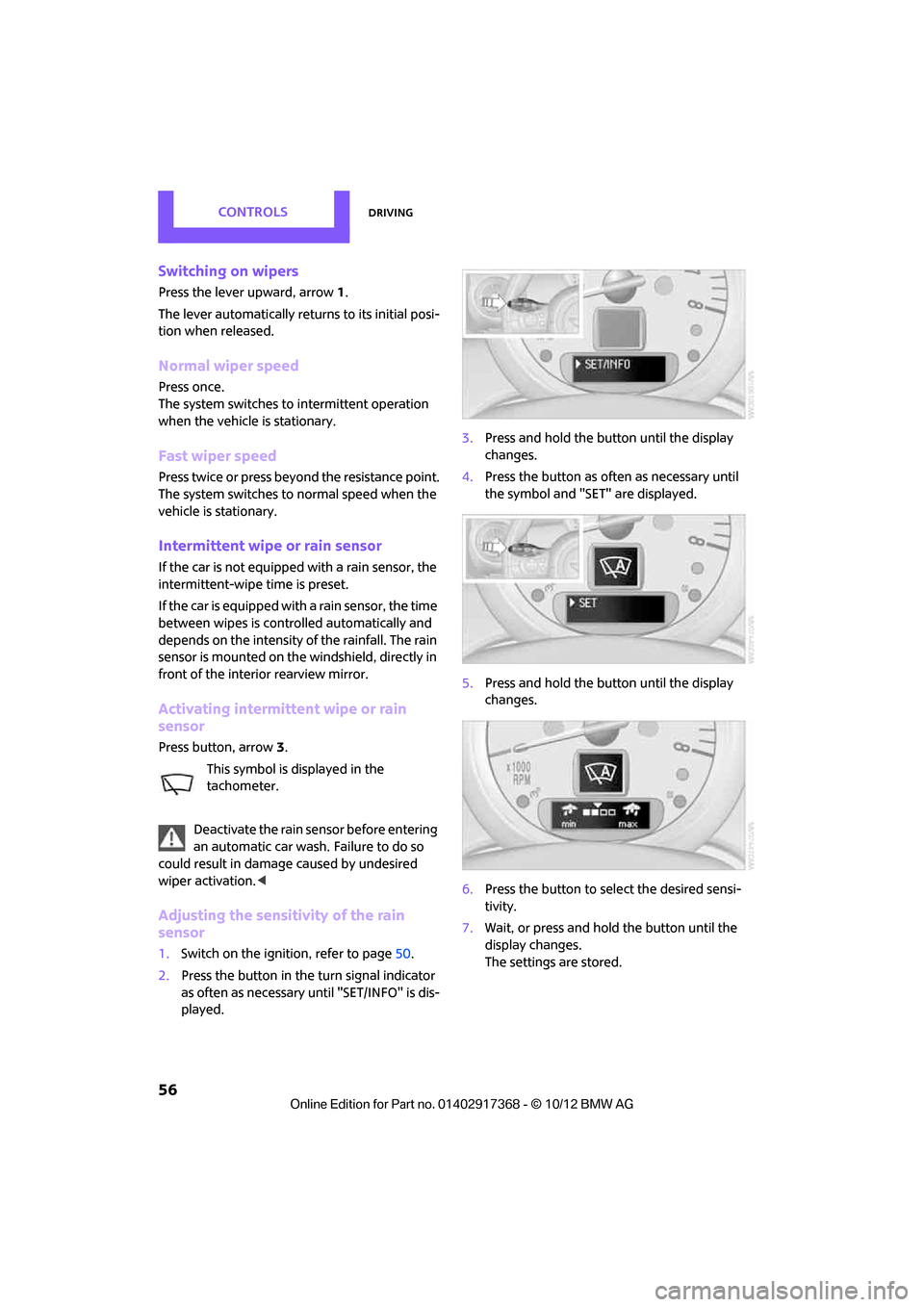
Adjusting the sensitivity of the rain
sensor
1.Switch on the ignition, refer to page 50.
2. Press the button in the turn signal indicator
as often as necessary until "SET/INFO" is dis-
played. 3.
Press and hold the button until the display
changes.
4. Press the button as often as necessary until
the symbol and "SET" are displayed.
5. Press and hold the button until the display
changes.
6. Press the button to se lect the desired sensi-
tivity.
7. Wait, or press and hold the button until the
display changes.
The settings are stored.
00320051004F004C00510048000300280047004C0057004C005200510003
Page 59 of 275
CONTROLSDriving
58
Fill with a mixture of washer fluid concentrate
and water and, if required, with a washer anti-
freeze according to manufacturer's recommen-
dations.
Do not fill with undiluted washer fluid concen-
trate and do not use wa ter alone; these can
damage the washer system.
Mix the water and antifreeze before filling
the washer fluid rese rvoir to make sure
the correct concentration is maintained. <
Capacity
Approx. 4.2 US quarts/4 liters.
Cruise control
The concept
Cruise control is available at vehicle speeds of at
least approx. 20 mph or 30 km/h. The car then
stores and maintains the speed that you specify
using the button on the steering wheel.
Do not use cruise control when driving at
constant speed is prevented by adverse
conditions, e.g. winding roads, dense traffic or
poor road conditions due to, e.g. snow, rain, ice
or loose surfaces. Otherwise, you could lose con-
trol of the vehicle and cause an accident as a
result. <
Activating
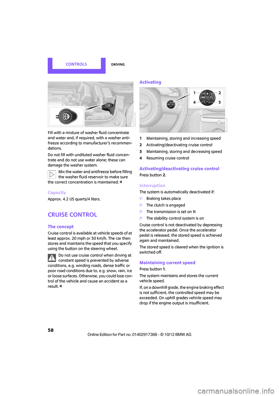
1Maintaining, storing and increasing speed
2 Activating/deactivating cruise control
3 Maintaining, storing and decreasing speed
4 Resuming cruise control
Activating/deactivating cruise control
Press button 2.
Interruption
The system is automati cally deactivated if:
> Braking takes place
> The clutch is engaged
> The transmission is set on N
> The stability control system is on
Cruise control is not deactivated by depressing
the accelerator pedal. Once the accelerator
pedal is released, the stored speed is achieved
again and maintained.
The stored speed is cleared when the ignition is
switched off.
Maintaining current speed
Press button 1.
The system maintains and stores the current
vehicle speed.
If, on a downhill grade, the engine braking effect
is not sufficient, the controlled speed may be
exceeded. On uphill grades vehicle speed may
drop if the engine output is insufficient.
00320051004F004C00510048000300280047004C0057004C005200510003
Page 74 of 275

Technology for driving comfort and safetyCONTROLS
73
Activating DSC
Press the switch again: the DSC indicator lamps
in the display elements go out.
For better control
The indicator lamp on the tachometer is
flashing:
DSC controls the dr iving and braking
forces.
The indicator lamp DSC OFF on the
speedometer is on and DSC OFF is dis-
played on the tachometer:
DSC is deactivated.
Dynamic Traction Control DTC
The concept
D TC is a ty pe o f DSC t hat is prop ulsion op timiz ed
for special road conditio ns such as uncleared
snowy roads. The syst em ensures maximum
propulsion though with restricted driving stabil-
ity. You therefore need to drive with suitable
caution.
In the following exceptional situations, it can be
useful to briefly activate DTC:
> When driving on snow-c overed inclines, in
slush, or on uncleared snowy roads
> When rocking the vehicle free, driving out of
deep snow or on loose surfaces
> When driving with snow chains
Activating DTC
Press the switch; the indicator lamp DSC OFF on
the speedometer comes on and TRACTION is
displayed on the tachometer.
The Dynamic Stability Control DSC is deacti-
vated; the Dynamic Traction Control DTC is acti-
vated.
For better control
The indicator lamp on the tachometer is
flashing:
DTC controls the driving and braking
forces.
The indicator lamp on the speedometer
is on and TRACTION is displayed on the
tachometer:
DTC is activated.
Deactivating DTC
Press switch again, the indicator lamps DSC OFF
on the speedometer and TRACTION on the
tachometer go out.
00320051004F004C00510048000300280047004C0057004C005200510003
Page 75 of 275
CONTROLSTechnology for driving comfort and safety
74
Deactivating both DTC and DSC
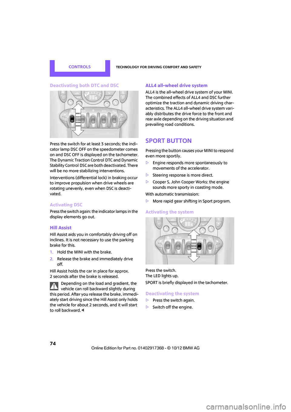
Press the switch for at least 3 seconds; the indi-
cator lamp DSC OFF on the speedometer comes
on and DSC OFF is displayed on the tachometer.
The Dynamic Traction Control DTC and Dynamic
Stability Control DSC are both deactivated. There
will be no more stabilizing interventions.
Interventions (differential lock) in braking occur
to improve propulsion when drive wheels are
rotating unevenly, even when DSC is deacti-
vated.
Activating DSC
Press the switch again: the indicator lamps in the
display elements go out.
Hill Assist
Hill Assist aids you in co mfortably driving off on
inclines. It is not necessary to use the parking
brake for this.
1. Hold the MINI with the brake.
2. Release the brake and immediately drive
off.
Hill Assist holds the car in place for approx.
2 seconds after the brake is released. Depending on the load and gradient, the
vehicle can roll backwa rd slightly during
this period. After you release the brake, immedi-
ately start driving since the Hill Assist only holds
the vehicle for about 2 seconds, and it will start
to roll backward. <
ALL4 all-wheel drive system
ALL4 is the all-wheel driv e system of your MINI.
The combined effects of ALL4 and DSC further
optimize the traction and dynamic driving char-
acteristics. The ALL4 all- wheel drive system vari-
ably distributes the drive force to the front and
rear axle depending on the driving situation and
prevailing road conditions.
Sport button
Pressing the button causes your MINI to respond
even more sportily.
> Engine responds more spontaneously to
movements of the accelerator.
> Steering response is more direct.
> Cooper S, John Cooper Works: the engine
sounds more sporty in coasting mode.
With automatic transmission:
> More rapid gear shifting in Sport program.
Activating the system
Press the switch.
The LED lights up.
SPORT is briefly displayed in the tachometer.
Deactivating the system
>Press the switch again.
> Switch off the engine.
00320051004F004C00510048000300280047004C0057004C005200510003
Page 83 of 275
CONTROLSTechnology for driving comfort and safety
82
upholstery in the center of the steering wheel,
on the instrument panel, the doors, and the roof
pillars as well as the sides of the headliner. Do
not attempt to remove or dismantle the steering
wheel.<
Do not touch the individual components
immediately after the system has been
triggered, because there is a danger of burns.
Have the testing, repair, removal, and disposal
o f a i r b a g g e n e r a t o r s e x e c u t e d o n l y b y y o u r M I N I
dealer or a workshop that has the required
explosives licenses.
Otherwise, unprofessiona l attempts to service
the system could lead to failure in an emergency
or undesired airbag activation, either of which
could result in personal injury. <
Warning notices and information about the air-
bags can also be found on the sun visors.
Automatic deactivation of the front
passenger airbags
The presence of a passenger in the front passen-
ger seat is detected by measuring the resistance
of the human body. The system correspondingly
activates or deactivates the front, side, and knee
airbags for the front passenger.
Make sure that the front passenger's feet
remain in the footwell; otherwise, it is not
possible to guarantee the function of the front
passenger airbags.<
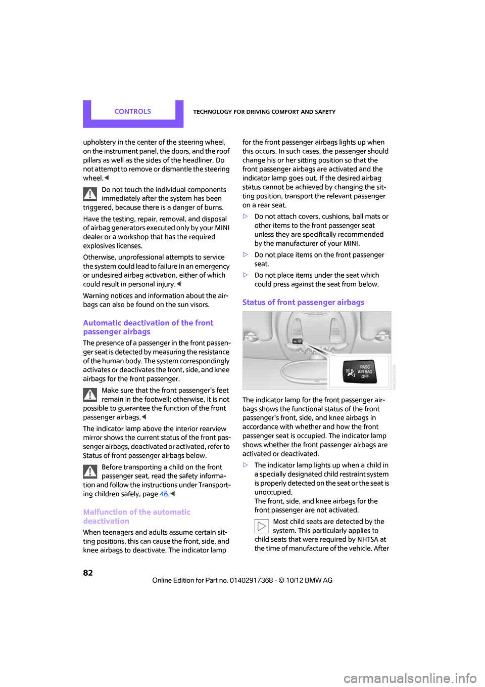
The indicator lamp above the interior rearview
mirror shows the current st atus of the front pas-
senger airbags, deactivated or activated, refer to
Status of front passe nger airbags below.
Before transporting a child on the front
passenger seat, read the safety informa-
tion and follow the instru ctions under Transport-
ing children safely, page 46.<
Malfunction of the automatic
deactivation
When teenagers and adults assume certain sit-
ting positions, this can cause the front, side, and
knee airbags to deactivate. The indicator lamp for the front passenger airbags lights up when
this occurs. In such case
s, the passenger should
change his or her sitting position so that the
front passenger airbags are activated and the
indicator lamp goes out. If the desired airbag
status cannot be achieved by changing the sit-
ting position, transport the relevant passenger
on a rear seat.
> Do not attach covers, cushions, ball mats or
other items to the front passenger seat
unless they are specif ically recommended
by the manufacturer of your MINI.
> Do not place items on the front passenger
seat.
> Do not place items under the seat which
could press against the seat from below.
Status of front passenger airbags
The indicator lamp for the front passenger air-
bags shows the functional status of the front
passenger's front, side, and knee airbags in
accordance with whet her and how the front
passenger seat is occupied. The indicator lamp
shows whether the front passenger airbags are
activated or deactivated.
> The indicator lamp lights up when a child in
a specially designated child restraint system
is properly detected on the seat or the seat is
unoccupied.
The front, side, and knee airbags for the
front passenger are not activated.
Most child seats are detected by the
system. This particularly applies to
child seats that were required by NHTSA at
the time of manufacture of the vehicle. After
00320051004F004C00510048000300280047004C0057004C005200510003
Page 84 of 275
Technology for driving comfort and safetyCONTROLS
83
installing a child seat, check that the indica-
tor lamp for the front passenger airbags
lights up. It indicates that the child seat has
been detected and that the front passenger
airbags are deactivated.<
> The indicator lamp does not come on as long
as a person of sufficient size and in a correct
sitting position is detected on the seat.
The front, side, and knee airbags for the
front passenger are activated.
Operational readiness of airbag system
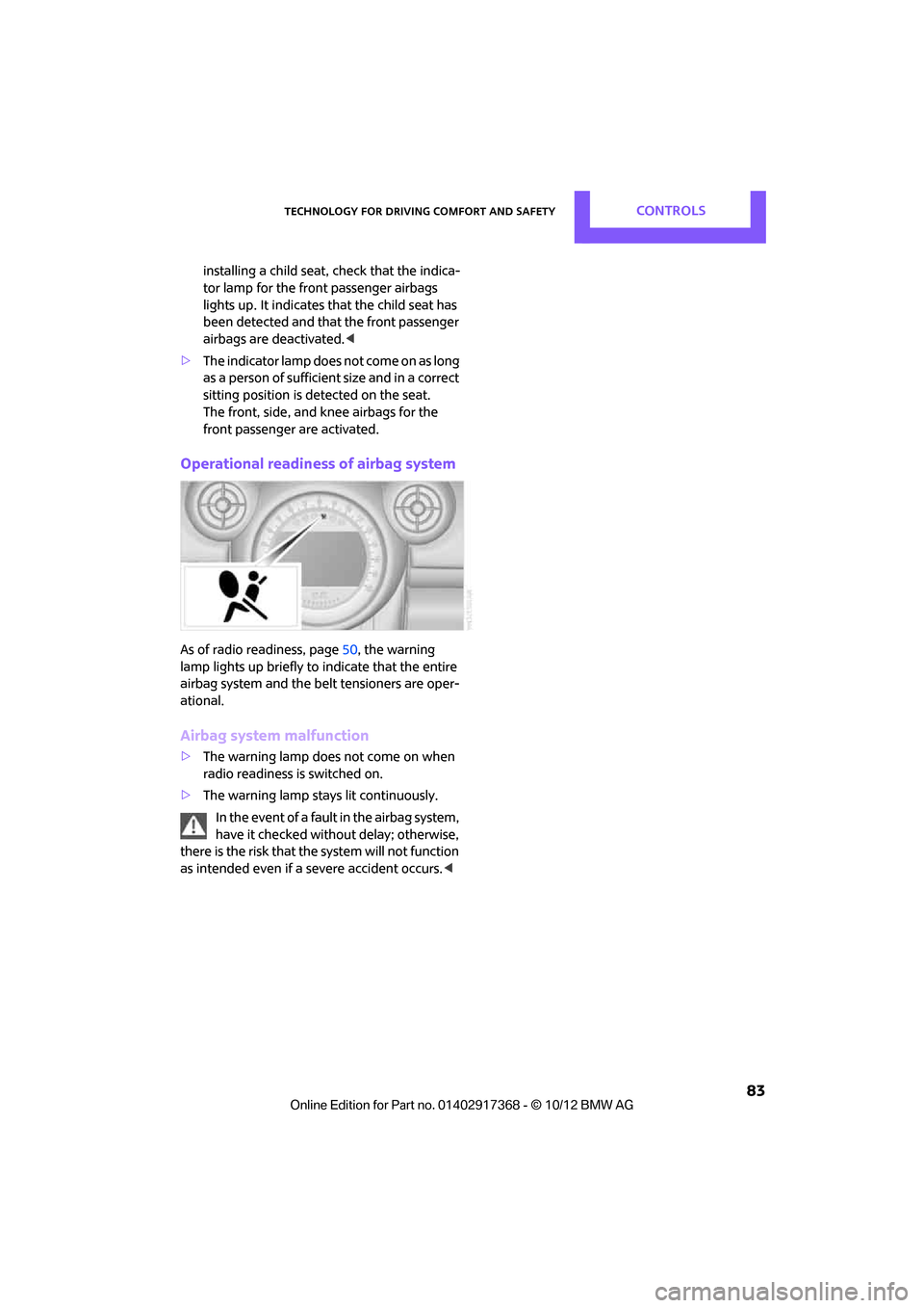
As of radio readiness, page 50, the warning
lamp lights up briefly to indicate that the entire
airbag system and the belt tensioners are oper-
ational.
Airbag system malfunction
> The warning lamp does not come on when
radio readiness is switched on.
> The warning lamp stays lit continuously.
In the event of a fault in the airbag system,
have it checked without delay; otherwise,
there is the risk that the system will not function
as intended even if a severe accident occurs. <
00320051004F004C00510048000300280047004C0057004C005200510003