warning light MINI Paceman 2013 Owner's Manual
[x] Cancel search | Manufacturer: MINI, Model Year: 2013, Model line: Paceman, Model: MINI Paceman 2013Pages: 275, PDF Size: 4.23 MB
Page 13 of 275
AT A GLANCECockpit
12
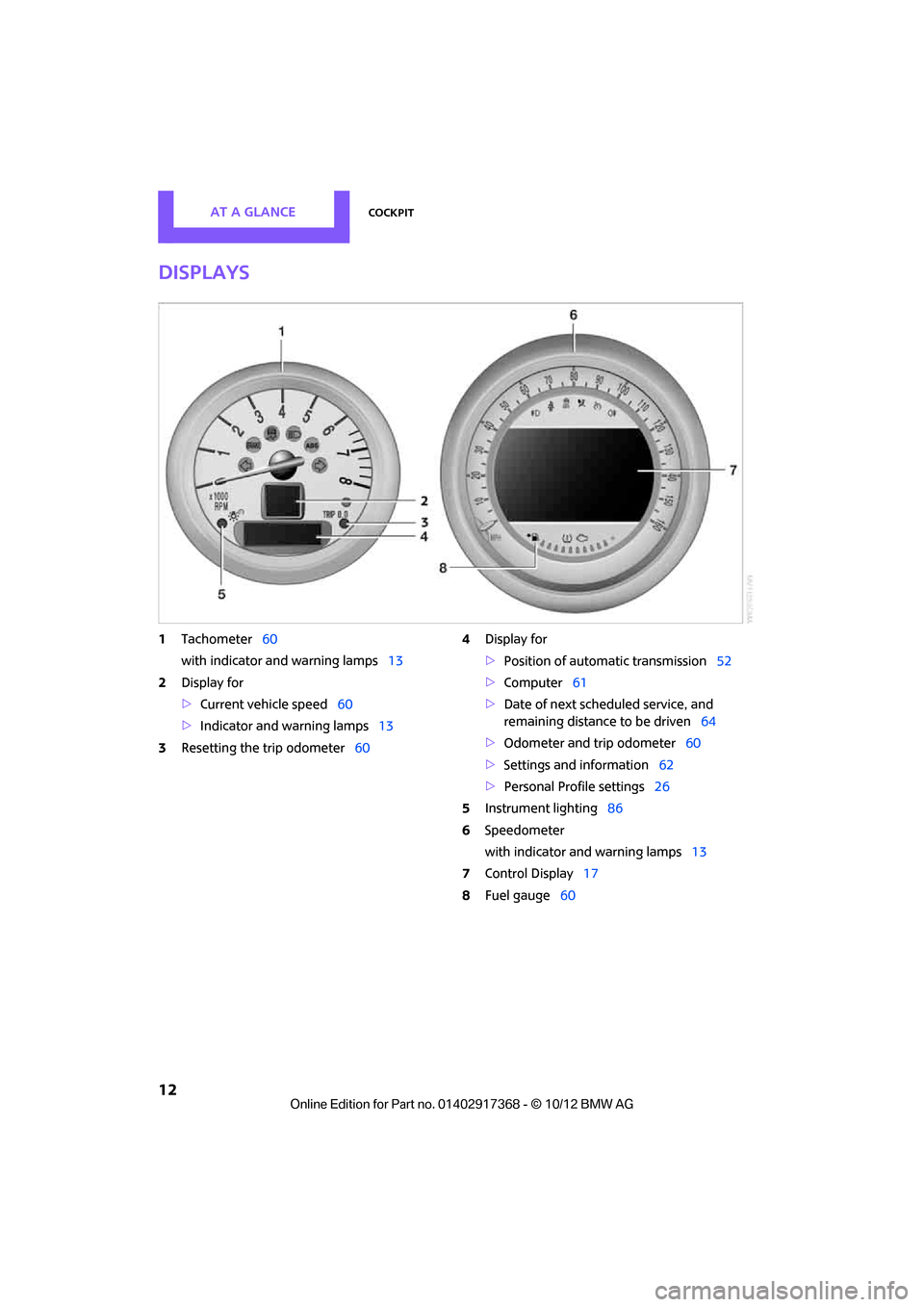
Displays
1Tachometer 60
with indicator and warning lamps 13
2 Display for
>Current vehicle speed 60
> Indicator and warning lamps 13
3 Resetting the trip odometer 604
Display for
>Position of automatic transmission 52
> Computer 61
> Date of next scheduled service, and
remaining distance to be driven 64
> Odometer and trip odometer 60
> Settings and information 62
> Personal Prof ile settings26
5 Instrument lighting 86
6 Speedometer
with indicator and warning lamps 13
7 Control Display 17
8 Fuel gauge 60
00320051004F004C00510048000300280047004C0057004C005200510003
Page 14 of 275
CockpitAT A GLANCE
13
Indicator and warning
lamps
The concept
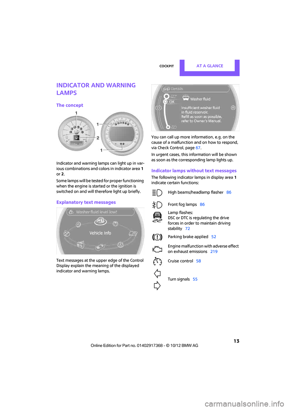
Indicator and warning lamps can light up in var-
ious combinations and colors in indicator area1
or 2.
Some lamps will be tested for proper functioning
when the engine is started or the ignition is
switched on and will therefore light up briefly.
Explanatory text messages
Text messages at the uppe r edge of the Control
Display explain the mean ing of the displayed
indicator and warning lamps. You can call up more information, e.g. on the
cause of a malfunction and on how to respond,
via Check Control, page
67.
In urgent cases, this information will be shown
as soon as the corresponding lamp lights up.
Indicator lamps without text messages
The following indicator lamps in display area 1
indicate certain functions:
High beams/headlamp flasher 86
Front fog lamps 86
Lamp flashes:
DSC or DTC is regulating the drive
forces in order to maintain driving
stability 72
Parking brake applied 52
Engine malfunction with adverse effect
on exhaust emissions 219
Cruise control 58
Turn signals 55
00320051004F004C00510048000300280047004C0057004C005200510003
Page 16 of 275
CockpitAT A GLANCE
15
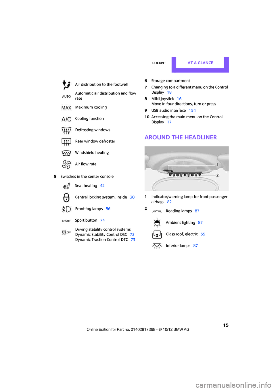
5Switches in the center console 6
Storage compartment
7 Changing to a differen t menu on the Control
Display 18
8 MINI joystick 16
Move in four directions, turn or press
9 USB audio interface 154
10 Accessing the main me nu on the Control
Display 17
Around the headliner
1Indicator/warning lamp for front passenger
airbags 82
Air distribution to the footwell
Automatic air distribution and flow
rate
Maximum cooling
Cooling function
Defrosting windows
Rear window defroster
Windshield heating
Air flow rate
Seat heating
42
Central locking system, inside 30
Front fog lamps 86
Sport button 74
Driving stability control systems
Dynamic Stability Control DSC 72
Dynamic Traction Control
DTC 73
2
Reading lamps 87
Ambient lighting 87
Glass roof, electric 35
Interior lamps 87
00320051004F004C00510048000300280047004C0057004C005200510003
Page 28 of 275
Opening and closingCONTROLS
27
Personal Profile settings
For more information on specific settings, refer
to the specified pages.
> Response of the central locking system
when the car is being unlocked 27
> Automatic locking of the vehicle 30
> Triple turn signal activation 55
> Settings for the displays on the onboard
computer, in the speedometer and in the
tachometer:
>12 h/24 h mode of the clock 66
> Date format 67
> Brightness of the Control Display 70
> Language on the Control Display 69
> Units of measure for fuel consumption,
distance covered/re maining distances
and temperature 64
> Light settings:
>Pathway lighting 85
> Daytime running lights 85
> Automatic climate control: activating/deac-
tivating the AUTO program, setting the tem-
perature, air volume and air distribution 90
> Entertainment:
>Audio volume 141
> Tone control 141
Central lock ing system
The concept
The central locking system is ready for operation
whenever the driver's door is closed.
The system simultaneously engages and
releases the locks on the following:
>Doors
> Tailgate
> Fuel filler flap
Operating from outside
>Via the remote control
> Using the door lock
> In cars with Comfor t Access, via the door
handles on the driver's and passenger's
sides
The anti-theft system is also operated at the
same time. It prevents the doors from being
unlocked using the lock buttons or door han-
dles. The remote control can also be used to
switch the welcome lamps, the interior light, and
the ambient lighting on and off. The alarm sys-
tem
is also activated or deactivated, page 32.
Operating from inside
Switch/button for central locking system,
page30.
In the event of a sufficiently severe accident, the
central locking system unlocks automatically. In
addition, the hazard warning flashers and inte-
rior lamps come on.
Opening and closing:
from outside
Persons or animals in a parked vehicle
could lock the doors from the inside. Take
the key with you when you leave the vehicle so
that the vehicle can be opened from the out-
side. <
Using the remote control
Unlocking
Press the button.
The welcome lamps and interior lamps come on.
Unlocking mode
You can also set which parts of the car are
unlocked. The setting is stored for the remote
control in use.
00320051004F004C00510048000300280047004C0057004C005200510003
Page 35 of 275
CONTROLSOpening and closing
34
Press the button again to lock the vehicle
again.<
Convenient opening with the remote control,
refer to page 28.
Locking
Press button 1.
For Convenient closing, press and hold button1.
In addition, the windows and the glass sunroof
are closed.
Unlocking the tailgate separately
Press the top side of the MINI emblem.
If the vehicle detects that a remote control
has been accidentally left inside the
locked vehicle's cargo area after the tailgate is
closed, the tailgate will reopen slightly. The haz-
ard warning flashers flash and an acoustic signal
sounds. <
Windows and glass roof, electric
If the engine is switched off, you can still operate
the windows and glass sunr oof so long as a door
or the tailgate has not been opened.
If the doors and tailgate are closed again and the
remote control is located inside the vehicle, the
windows and the glass sunroof can be operated
again.
Insert the remote control into the ignition lock to
be able to operate the windows or glass roof
when the engine is switched off and the doors
are open.
Switching on radio readiness
Switch on radio readiness by pressing the Start/
Stop button, page 50.
Do not depress the brake or the clutch;
otherwise, the engine will start. <
Starting the engine
The engine can be started or the ignition can be
switched on when a remote control is inside the
vehicle. It is not necessary to insert a remote
control into the ignition lock, page 50.
Switching off the engine in cars with
automatic transmission
The engine can only be switched off when the
selector lever is in position P, page 52.
To switch the engine off when the selector lever
is in position N, the remote control must be in
the ignition lock.
Before driving a vehicle with automatic
transmission into a car wash
1. Insert remote control into ignition lock.
2. Depress the brake.
3. Move the selector le ver to position N.
4. Switch off the engine.
The vehicle can roll.
Malfunction
Comfort Access may malf unction due to local
radio waves.
If this happens, open or close the vehicle via the
buttons on the remote control or using the inte-
grated key.
Insert the remote control into the ignition lock
and start the engine.
Warning lamps
The warning lamp lights up when an
attempt is made to start the engine: the
engine cannot be started. The remote
control is not inside the vehicle or is malfunc-
tioning. Take the remote control with you inside
the vehicle or have it checked. If necessary,
insert another remote co ntrol into the ignition
lock.
00320051004F004C00510048000300280047004C0057004C005200510003
Page 36 of 275
Opening and closingCONTROLS
35
The warning lamp lights up when the
engine is running: the remote control is
no longer inside the vehicle. After the
engine is switched off, the engine can only be
restarted within approx. 10 seconds.
The indicator lamp lights up and a mes-
sage appears on the Control Display:
replace the battery in the remote con-
trol.
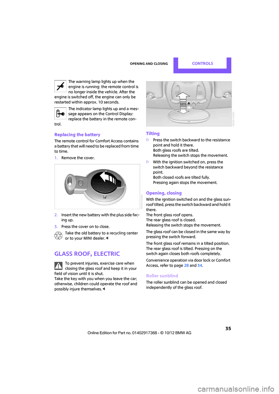
Replacing the battery
The remote control for Comfort Access contains
a battery that will need to be replaced from time
to time.
1. Remove the cover.
2. Insert the new battery with the plus side fac-
ing up.
3. Press the cover on to close.
Take the old battery to a recycling center
or to your MINI dealer. <
Glass roof, electric
To prevent injuries, exercise care when
closing the glass roof and keep it in your
field of vision until it is shut.
Take the key with you when you leave the car;
otherwise, children could operate the roof and
possibly injure themselves. <
Tilting
>Press the switch backwa rd to the resistance
point and hold it there.
Both glass roofs are tilted.
Releasing the switch stops the movement.
> With the ignition switched on, press the
switch backward beyo nd the resistance
point.
Both closed roofs are tilted fully.
Pressing again st ops the movement.
Opening, closing
With the ignition switched on and the glass sun-
roof tilted, press the swit ch backward and hold it
there.
The front glass roof opens.
The rear glass roof is closed.
Releasing the switch stops the movement.
The glass roof can be closed in the same way by
pressing the switch forward.
The front glass roof remains in a tilted position.
The rear glass roof is tilted. Pressing on the
switch again closes bo th roofs completely.
Convenience operation via door lock or Comfort
Access, refer to page 28 and34.
Roller sunblind
The roller sunblind can be opened and closed
independently of the glass roof.
00320051004F004C00510048000300280047004C0057004C005200510003
Page 60 of 275
DrivingCONTROLS
59
Increasing speed
Press button1 repeatedly until the desired
speed is reached. Every time you press the but-
ton, the speed increases by approx. 1 mph or
1km/h.
Accelerating using the button
Press and hold button 1.
The vehicle accelerates wi thout pressure on the
accelerator pedal. After the button is released,
the driving speed is maintained and stored.
Decreasing speed
Press button 3 repeatedly until the desired
speed is reached.
The functions here are the same as for increas-
ing the speed or accelerating, except that the
speed will be decreased.
Resuming a speed stored beforehand
Press button 4.
The last speed stored is achieved again and
maintained.
The stored speed is cleared when the ignition is
switched off.
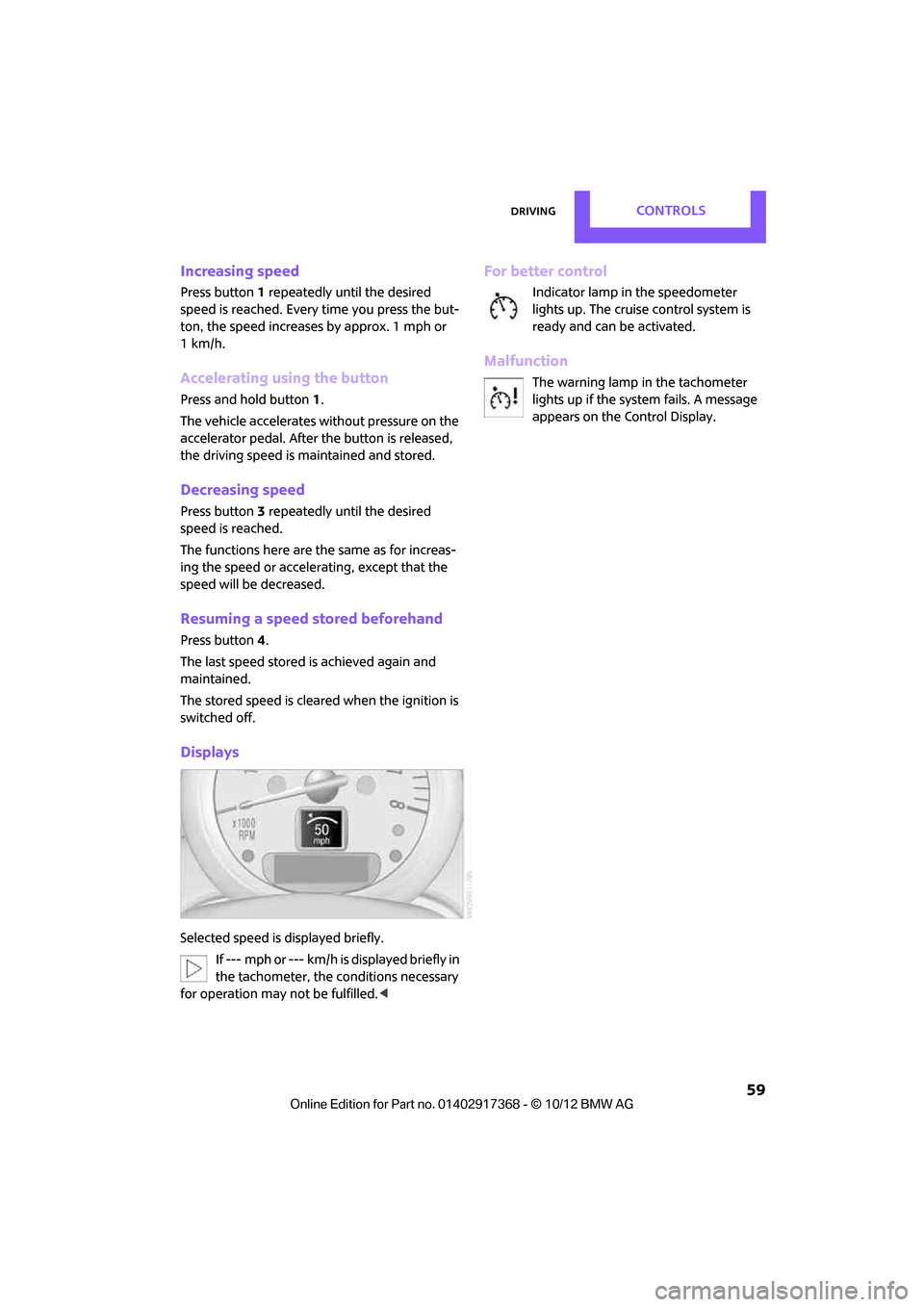
Displays
Selected speed is displayed briefly. If --- mph or --- km/h is displayed briefly in
the tachometer, the conditions necessary
for operation may not be fulfilled.<
For better control
Indicator lamp in the speedometer
lights up. The cruise control system is
ready and can be activated.
Malfunction
The warning lamp in the tachometer
lights up if the system fails. A message
appears on the Control Display.
00320051004F004C00510048000300280047004C0057004C005200510003
Page 62 of 275
Controls overviewCONTROLS
61
The following information is displayed sequen-
tially:
> Trip odometer
> Time
> External temperature
Trip odometer
To display trip recorder:
Briefly press button 3.
Resetting the trip odometer:
While the trip recorder is displayed and the igni-
tion is switched on, press button 3.
Time
To set time, see page 66.
External temperature, external
temperature warning
When the displayed temperature sinks to
approx. +37 7/+3 6, a signal sounds and a
warning lamp lights up. There is an increased
risk of black ice.
Even at temperatures above +37 7/+3 6
ice can form. Therefore, drive carefully,
e.g. on bridges and sections of road in the
shade; otherwise, there is an increased accident
risk. <
Units of measure
Select the respective units of measure, miles or
km for the odometer as well as 7 or 6 for the
external temperature, page 64.
Computer
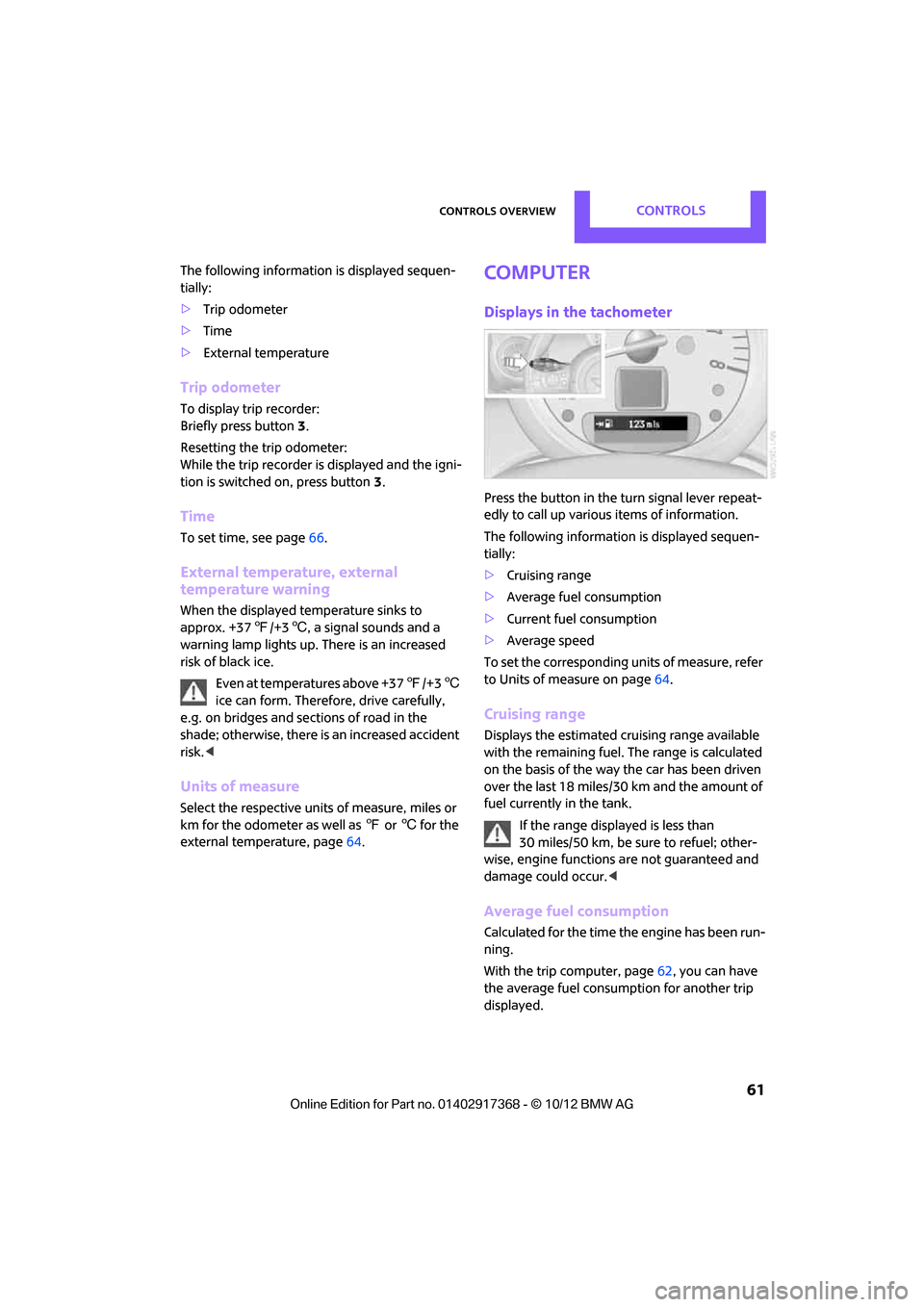
Displays in the tachometer
Press the button in the turn signal lever repeat-
edly to call up variou s items of information.
The following information is displayed sequen-
tially:
> Cruising range
> Average fuel consumption
> Current fuel consumption
> Average speed
To set the corresponding units of measure, refer
to Units of measure on page 64.
Cruising range
Displays the estimated cruising range available
with the remaining fuel. The range is calculated
on the basis of the way the car has been driven
over the last 18 miles/30 km and the amount of
fuel currently in the tank.
If the range displayed is less than
30 miles/50 km, be sure to refuel; other-
wise, engine functions are not guaranteed and
damage could occur.<
Average fuel consumption
Calculated for the time the engine has been run-
ning.
With the trip computer, page 62, you can have
the average fuel consumption for another trip
displayed.
00320051004F004C00510048000300280047004C0057004C005200510003
Page 68 of 275
Controls overviewCONTROLS
67
4.Turn MINI joystick until the desired time
zone is set and press the MINI joystick.
The time zone is stored.
Date
Setting date
1."Settings"
2. "Time/Date"
3. "Date:"
4. Turn MINI joystick until the desired day is
displayed and press the MINI joystick.
5. Create the necessary settings for the month
and year.
The date is stored.
Setting the date format
1. "Settings"
2. "Time/Date"
3. "Format:"
4. Select the desired format.
The settings are stored for the remote control
currently in use, refer also to Personal Profile on
page 26.
Check Control
The concept
The Check Control monitors vehicle functions
and alerts you to any ma lfunctions in the sys-
tems monitored. Check Control messages involve indicator and warning lamps in the dis-
play and, in some circ
umstances, an acoustic
signal as well as text messages at the bottom of
the Control Display.
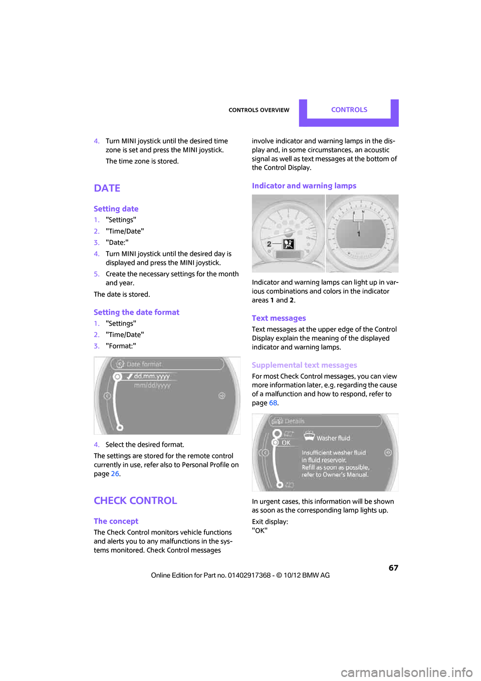
Indicator and warning lamps
Indicator and warning lamps can light up in var-
ious combinations and colors in the indicator
areas 1 and 2.
Text messages
Text messages at the upper edge of the Control
Display explain the meaning of the displayed
indicator and warning lamps.
Supplemental text messages
For most Check Control messages, you can view
more information later, e.g. regarding the cause
of a malfunction and how to respond, refer to
page 68.
In urgent cases, this information will be shown
as soon as the corresponding lamp lights up.
Exit display:
"OK"
00320051004F004C00510048000300280047004C0057004C005200510003
Page 72 of 275

Technology for driving comfort and safetyCONTROLS
71
Technology for driving comfort and
safety
Vehicle equipment
In this chapter, all production, country, and
optional equipment that is offered in the model
range is described. Equipment is also described
that is not available because of, for example,
selected options or count ry version. This also
applies to safety related functions and systems.
Park Distance Control
PDC
The concept
PDC assists you with parking in reverse. Acoustic
signals and a visual indicator
warn you of the
presence of an object behind the vehicle. The
measurement is carried out by four ultrasonic
sensors in the rear bumper.
These sensors have a range of approx.
6.5ft/2m. However, an acoustic warning
does not sound until an object is approx. 24 in/
60 cm from the rear corner sensors or approx.
5 ft/1.50 m from the rear center sensors. PDC is
a parking aid that can indicate objects when
they are approached slowly, as is usually the
case when parking. Avoid approaching an
object at high speed; otherwise, physical cir-
cumstances may lead to the system warning
being issued too late. <
Automatic mode
With the engine running or the ignition switched
on, the system is activated automatically after
approx. 1 second when you engage reverse
gear or move the automatic transmission selec-
tor lever to position R. Wait this short period
before driving.
Acoustic signals
As the distance between vehicle and object
decreases, the intervals between the tones
become shorter. If the distance to the nearest
object falls to below roughly 1 ft/30 cm, then a
continuous tone sounds.
If the distance remains constant, e.g. when driv-
ing parallel to a wall, th e acoustic signal stops
after approx. 3 seconds.
Malfunction
Indicator lamp lights up. PDC has failed.
A message appears on the Control Dis-
play. Have the system checked.
To avoid this problem, keep the sensors clean
and free of ice or snow in order to ensure that
they will continue to operate effectively. When
using a high-pressure clea ner, do not direct the
jet toward the sensors for lengthy periods and
only spray from a distance of at least 4 in/10 cm.
PDC with visual warning
To have the system show distances to objects on
the Control Display. The contours of distant
objects are shown on the Control Display even
before the acoustic sign al sounds. The display
appears on the Control Di splay as soon as the
transmission is shifted in to reverse or the selec-
tor lever is moved into the R position.
System limitations
Even with PDC, final re sponsibility for esti-
mating the distance between the vehicle
and any obstructions always remains with the
driver. Sensors, too, ha ve blind spots in which
objects cannot be detected. Moreover, ultra-
sonic detection can reach its physical limits with
objects such as trailer tow bars and couplings,
thin and wedge-shaped objects, etc. Low
objects already indicated, such as curbs, may
00320051004F004C00510048000300280047004C0057004C005200510003