battery MINI Paceman 2014 (Mini Connected) User Guide
[x] Cancel search | Manufacturer: MINI, Model Year: 2014, Model line: Paceman, Model: MINI Paceman 2014Pages: 282, PDF Size: 6.76 MB
Page 99 of 282

ClimateVehicle equipment
This chapter describes all series equipment as
well as country-specific and special equipment
offered for this model series.Therefore, it alsodescribes equipment that may not be found in
your vehicle, for instance due to the selected
special equipment or the country version. This
also applies to safety-related functions and sys‐
tems.
Air conditioning
1Air volume2Cooling function3Recirculated air mode4Temperature5Rear window defroster6Vent settings7Windshield heatingAir volume
Vary the air volume. The higher
the rate, the more effective the
heating or cooling will be.
The air flow rate may be reduced
or the blower may be switched
off entirely to save on battery power.Switching the system on/off
Turn the rotary switch for the air volume to 0.
The blower and air conditioner are completely switched off and the air supply is cut off.
Set any air volume to switch on the air condi‐
tioning.Seite 99ClimateControls99
Online Edition for Part no. 01 40 2 911 544 - VI/13
Page 100 of 282
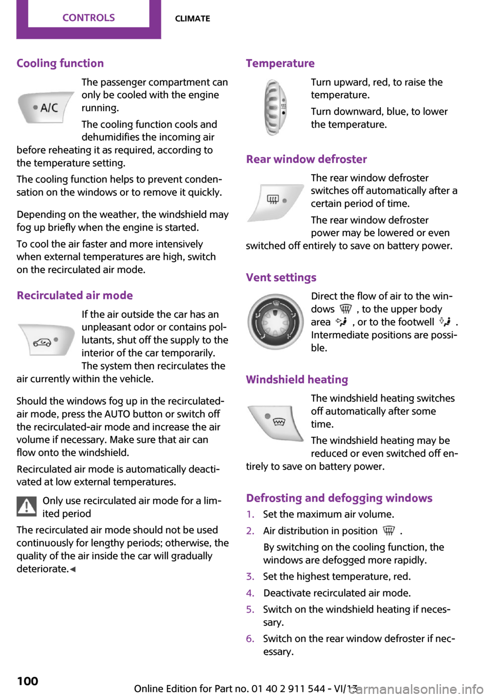
Cooling functionThe passenger compartment can
only be cooled with the engine
running.
The cooling function cools and
dehumidifies the incoming air
before reheating it as required, according to
the temperature setting.
The cooling function helps to prevent conden‐
sation on the windows or to remove it quickly.
Depending on the weather, the windshield may
fog up briefly when the engine is started.
To cool the air faster and more intensively
when external temperatures are high, switch
on the recirculated air mode.
Recirculated air mode If the air outside the car has an
unpleasant odor or contains pol‐
lutants, shut off the supply to the
interior of the car temporarily.
The system then recirculates the
air currently within the vehicle.
Should the windows fog up in the recirculated-
air mode, press the AUTO button or switch off
the recirculated-air mode and increase the air
volume if necessary. Make sure that air can
flow onto the windshield.
Recirculated air mode is automatically deacti‐
vated at low external temperatures.
Only use recirculated air mode for a lim‐
ited period
The recirculated air mode should not be used
continuously for lengthy periods; otherwise, the
quality of the air inside the car will gradually
deteriorate. ◀Temperature
Turn upward, red, to raise thetemperature.
Turn downward, blue, to lower
the temperature.
Rear window defroster The rear window defroster
switches off automatically after a
certain period of time.
The rear window defroster
power may be lowered or even
switched off entirely to save on battery power.
Vent settings Direct the flow of air to the win‐
dows
, to the upper body
area
, or to the footwell .
Intermediate positions are possi‐
ble.
Windshield heating The windshield heating switches
off automatically after some
time.
The windshield heating may be
reduced or even switched off en‐
tirely to save on battery power.
Defrosting and defogging windows
1.Set the maximum air volume.2.Air distribution in position .
By switching on the cooling function, the
windows are defogged more rapidly.3.Set the highest temperature, red.4.Deactivate recirculated air mode.5.Switch on the windshield heating if neces‐
sary.6.Switch on the rear window defroster if nec‐
essary.Seite 100ControlsClimate100
Online Edition for Part no. 01 40 2 911 544 - VI/13
Page 102 of 282
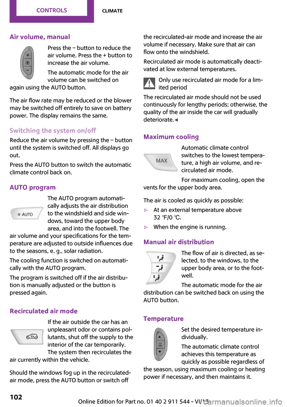
Air volume, manualPress the – button to reduce the
air volume. Press the + button to
increase the air volume.
The automatic mode for the air volume can be switched on
again using the AUTO button.
The air flow rate may be reduced or the blower
may be switched off entirely to save on battery
power. The display remains the same.
Switching the system on/off
Reduce the air volume by pressing the – button
until the system is switched off. All displays go
out.
Press the AUTO button to switch the automatic
climate control back on.
AUTO program The AUTO program automati‐
cally adjusts the air distribution
to the windshield and side win‐
dows, toward the upper body
area, and into the footwell. The
air volume and your specifications for the tem‐
perature are adjusted to outside influences due
to the seasons, e. g., solar radiation.
The cooling function is switched on automati‐
cally with the AUTO program.
The program is switched off if the air distribu‐
tion is manually adjusted or the button is
pressed again.
Recirculated air mode If the air outside the car has an
unpleasant odor or contains pol‐
lutants, shut off the supply to the
interior of the car temporarily.
The system then recirculates the
air currently within the vehicle.
Should the windows fog up in the recirculated-
air mode, press the AUTO button or switch offthe recirculated-air mode and increase the air
volume if necessary. Make sure that air can
flow onto the windshield.
Recirculated air mode is automatically deacti‐
vated at low external temperatures.
Only use recirculated air mode for a lim‐
ited period
The recirculated air mode should not be used
continuously for lengthy periods; otherwise, the
quality of the air inside the car will gradually
deteriorate. ◀
Maximum cooling Automatic climate control
switches to the lowest tempera‐
ture, a high air volume, and re‐
circulated air mode.
For maximum cooling, open the
vents for the upper body area.
The air is cooled as quickly as possible:▷At an external temperature above
32 ℉/0 ℃.▷When the engine is running.
Manual air distribution
The flow of air is directed, as se‐
lected, to the windows, to the
upper body area, or to the foot‐
well.
The automatic mode for the air
distribution can be switched back on using the
AUTO button.
Temperature Set the desired temperature in‐
dividually.
The automatic climate control
achieves this temperature as
quickly as possible regardless of
the season, using maximum cooling or heating power if necessary, and then maintains it.
Seite 102ControlsClimate102
Online Edition for Part no. 01 40 2 911 544 - VI/13
Page 109 of 282

Connecting electrical de‐
vices
The lighter socket can be used as a socket for
electrical equipment while the engine is run‐
ning or when the ignition is switched on. The
total load of all sockets must not exceed
140 watts at 12 volt.
Avoid damaging the sockets by attempting to
insert plugs of unsuitable shape or size.
Do not connect the charger to the socket
Do not connect the battery charger to the
socket installed in the vehicle at the factory as this could damage the battery. ◀
Replace the cover after use
Replace the lighter or socket cover after
use; otherwise, objects that fall into the lighter
socket or power socket could cause a short cir‐
cuit. ◀
Socket in the center console
Remove the cover or lighter, refer to page 108,
from the socket.
Socket in the rear
MINI Countryman
Take out the cover.
MINI Paceman
Take out the cover.
Socket in the cargo area
MINI Countryman
Take out the cover.
MINI Paceman
Take out the cover.
Seite 109Interior equipmentControls109
Online Edition for Part no. 01 40 2 911 544 - VI/13
Page 134 of 282
Navigation systemVehicle equipment
This chapter describes all series equipment as
well as country-specific and special equipment
offered for this model series.Therefore, it also
describes equipment that may not be found in
your vehicle, for instance due to the selected
special equipment or the country version. This
also applies to safety-related functions and sys‐
tems.
General information The navigation system can determine the pre‐
cise position of the vehicle, with the aid of sat‐
ellites and vehicle sensors, and can reliably
guide you to every entered destination.
Entries in stationary vehicle
Enter data only when the vehicle is sta‐
tionary, and always give priority to the applica‐
ble traffic regulations in the event of any con‐
tradiction between traffic and road conditions
and the instructions issued by the navigation
system. Failure to take to this precaution can
place you in violation of the law and put vehicle
occupants and other road users in danger. ◀
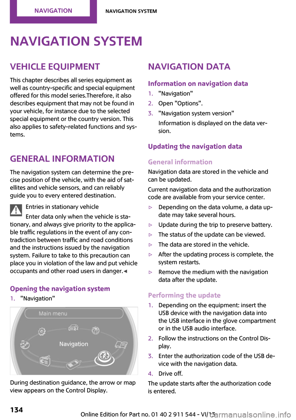
Opening the navigation system1."Navigation"
During destination guidance, the arrow or map
view appears on the Control Display.
Navigation data
Information on navigation data1."Navigation"2.Open "Options".3."Navigation system version"
Information is displayed on the data ver‐
sion.
Updating the navigation data
General information
Navigation data are stored in the vehicle and
can be updated.
Current navigation data and the authorization
code are available from your service center.
▷Depending on the data volume, a data up‐
date may take several hours.▷Update during the trip to preserve battery.▷The status of the update can be viewed.▷The data are stored in the vehicle.▷After the updating process is complete, the
system restarts.▷Remove the medium with the navigation
data after the update.
Performing the update
1.Depending on the equipment: insert the
USB device with the navigation data into
the USB interface in the glove compartment
or in the USB audio interface.2.Follow the instructions on the Control Dis‐
play.3.Enter the authorization code of the USB de‐
vice with the navigation data.4.Drive off.
The update starts after the authorization code
is entered.
Seite 134NavigationNavigation system134
Online Edition for Part no. 01 40 2 911 544 - VI/13
Page 153 of 282
What to do if...Vehicle equipment
This chapter describes all series equipment as
well as country-specific and special equipment
offered for this model series.Therefore, it also
describes equipment that may not be found in
your vehicle, for instance due to the selected
special equipment or the country version. This
also applies to safety-related functions and sys‐
tems.
What to do if...▷The current transmission position cannot be
displayed?
The vehicle is located in an unrecognized
region, is in a poor reception area, or the
system is currently determining the posi‐
tion. Reception is usually best when you
have an unobstructed view of the sky.▷The destination without street information
is not used for route guidance?
When city has been input, no downtown
can be determined. Input any street in the
selected city and start destination guid‐
ance.▷The destination is not used for route guid‐
ance?
The destination data are not contained in
the navigation data. Select a destination
that is as close as possible to the original.▷Letters for destination input cannot be se‐
lected?
The stored data do not contain the data of
the destination. Select a goal that is as close
as possible to the original.▷Is the map displayed in shades of gray?
"Traffic conditions/gray map" active:The Control Display changes to a black and
white display. This enables a better view of
the traffic bulletins.▷Spoken instructions are no longer output
during route guidance in front of intersec‐
tions?
The area has not yet been fully recorded, or
you have left the recommended route and
the system requires a few seconds to calcu‐
late a new route suggestion.▷Does the navigation system fail to react to
entries?
If the battery was disconnected, it takes up
to 10 minutes for the system to becoming
functional again.Seite 153What to do if...Navigation153
Online Edition for Part no. 01 40 2 911 544 - VI/13
Page 183 of 282
▷A multi-character passkey may be needed.▷Did it take longer than 30 seconds to enter
the passkey? Repeat the pairing procedure.▷Are too many Bluetooth devices connected
to the mobile phone or vehicle? Delete con‐
nections with other devices if necessary.▷The mobile phone is in power-save mode
or has only a limited remaining battery life.
Charge the mobile phone via the charging
cable.▷Depending on the mobile phone, it is possi‐
ble that only one mobile phone can be con‐
nected to the vehicle. Unpair the connected
mobile phone from the vehicle and pair
and connect only one mobile phone.
The mobile phone no longer reacts.
▷Switch the mobile phone off and on again.▷Is the ambient temperature too high or
low? Do not expose the mobile phone to
extreme environmental conditions.
No phone book entries or only some phone
book entries are displayed, or they are incom‐
plete.
▷Transmission of the phone book entries is
not yet complete.▷It is possible that only the phone book en‐
tries of the mobile phone or the SIM card
are transmitted.▷It may not be possible to display phone
book entries with special characters.▷The number of phone book entries to be
stored is too high.▷Is the data volume of the contact too large,
e. g., due to stored information such as
notes? Reduce the data volume of the con‐
tact.
The phone connection quality is poor.
▷The strength of the Bluetooth signal on the
mobile phone can be adjusted, depending
on the mobile phone.▷Place the mobile phone in the area of the
center console.If all points in this list have been checked and
the required function is still not available, con‐
tact Customer Relations or the service center.
Controls Adjusting the volume
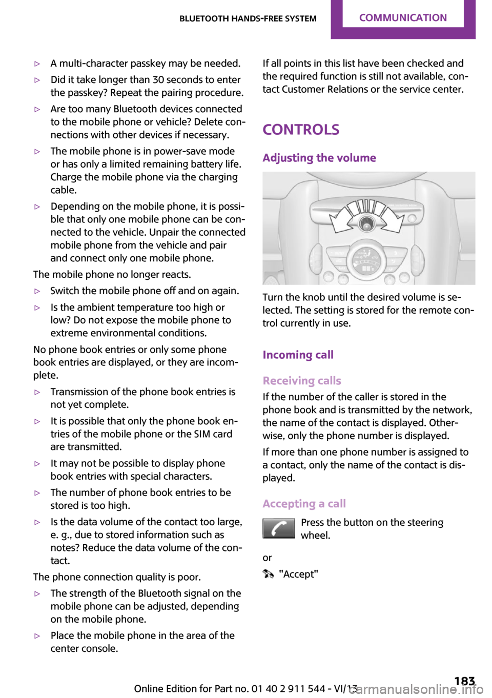
Turn the knob until the desired volume is se‐
lected. The setting is stored for the remote con‐
trol currently in use.
Incoming call
Receiving calls If the number of the caller is stored in the
phone book and is transmitted by the network,
the name of the contact is displayed. Other‐
wise, only the phone number is displayed.
If more than one phone number is assigned to
a contact, only the name of the contact is dis‐
played.
Accepting a call Press the button on the steering
wheel.
or
"Accept"
Seite 183Bluetooth hands-free systemCommunication183
Online Edition for Part no. 01 40 2 911 544 - VI/13
Page 190 of 282
Bluetooth mobile phone
preparation packageVehicle equipment This chapter describes all series equipment as
well as country-specific and special equipment
offered for this model series.Therefore, it also
describes equipment that may not be found in
your vehicle, for instance due to the selected
special equipment or the country version. This
also applies to safety-related functions and sys‐
tems.
At a glance The concept
Mobile phones or other external devices such
as audio players can be connected to the vehi‐
cle via Bluetooth.
Bluetooth® is a registered trademark of Blue‐
tooth® SIG, Inc.
After these devices are paired once, they are
recognized automatically when the ignition is
switched on as soon as they are in the vehicle
and can then be operated via the onboard
monitor, using the buttons on the steering
wheel, and via voice activation.
Depending on their functionality, external devi‐
ces can be used via the vehicle as a telephone
or as an audio source. The telephone functions
are described in the following. Operating the
audio functions, refer to page 173.
Up to four external devices can be paired.
Certain functions may need to be enabled by the mobile phone provider or service provider.
Using the mobile phone while driving
Make entries only when traffic and road
conditions allow. Do not hold the mobile phone
in your hand while you are driving; use thehands-free system instead. If you do not ob‐
serve this precaution, you can endanger the ve‐
hicle occupants and other road users. ◀
Snap-in adapter
The snap-in adapter is used to:▷Hold the mobile phone.▷Recharge the battery.▷Connect the mobile phone to an outside
antenna of the vehicle.
This provides for better network reception
and consistent sound quality.
Approved mobile phones
Displaying the vehicle identification
number and software part number
The vehicle identification number and software
part number are needed to determine which
mobile phones are supported by the mobile
phone preparation package. The software ver‐
sion of the mobile phone may also be required.
1."Telephone"2.Open "Options".3."Bluetooth® info"4."Display system information"
These approved mobile phones with a certain
software version, support the vehicle functions
described below.
Malfunctions may occur with other mobile
phones or software versions.
Do not operate a mobile phone that is con‐
nected to the vehicle on the mobile phone key‐
pad, as this may lead to a malfunction.
Seite 190CommunicationBluetooth mobile phone preparation package190
Online Edition for Part no. 01 40 2 911 544 - VI/13
Page 200 of 282
Snap-in adapter
General information More information on compatible snap-in
adapters that support the functions of the mo‐
bile phone is available at the service center.
Notes At high temperatures, the charging function of
the mobile phone may be limited and functions
may not be executed.
When using the mobile phone via the vehicle,
note the operating instructions of the mobile
phone.
Installation position In the center armrest.
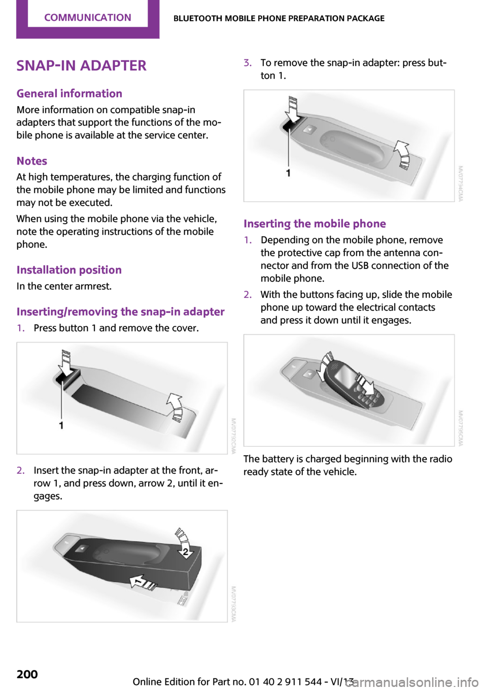
Inserting/removing the snap-in adapter1.Press button 1 and remove the cover.2.Insert the snap-in adapter at the front, ar‐
row 1, and press down, arrow 2, until it en‐
gages.3.To remove the snap-in adapter: press but‐
ton 1.
Inserting the mobile phone
1.Depending on the mobile phone, remove
the protective cap from the antenna con‐
nector and from the USB connection of the
mobile phone.2.With the buttons facing up, slide the mobile
phone up toward the electrical contacts
and press it down until it engages.
The battery is charged beginning with the radio
ready state of the vehicle.
Seite 200CommunicationBluetooth mobile phone preparation package200
Online Edition for Part no. 01 40 2 911 544 - VI/13
Page 232 of 282
Engine compartmentVehicle equipment
This chapter describes all series equipment as
well as country-specific and special equipment
offered for this model series.Therefore, it alsodescribes equipment that may not be found in
your vehicle, for instance due to the selected
special equipment or the country version. This
also applies to safety-related functions and sys‐
tems.
Important features in the engine compartment
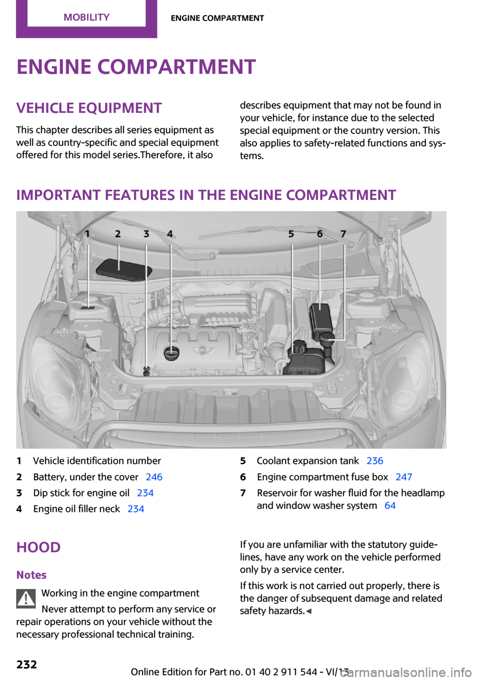
1Vehicle identification number2Battery, under the cover 2463Dip stick for engine oil 2344Engine oil filler neck 2345Coolant expansion tank 2366Engine compartment fuse box 2477Reservoir for washer fluid for the headlamp
and window washer system 64Hood
Notes Working in the engine compartment
Never attempt to perform any service or
repair operations on your vehicle without the
necessary professional technical training.If you are unfamiliar with the statutory guide‐
lines, have any work on the vehicle performed
only by a service center.
If this work is not carried out properly, there is
the danger of subsequent damage and related
safety hazards. ◀Seite 232MobilityEngine compartment232
Online Edition for Part no. 01 40 2 911 544 - VI/13