turn signal MINI Paceman 2014 (Mini Connected) User Guide
[x] Cancel search | Manufacturer: MINI, Model Year: 2014, Model line: Paceman, Model: MINI Paceman 2014Pages: 282, PDF Size: 6.76 MB
Page 159 of 282
All saved stations are stored for the remote
control currently in use.
Changing the station Turn and press the MINI joystick.
or
Press the button
or
Press the buttons on the steering wheel.
Storing a station
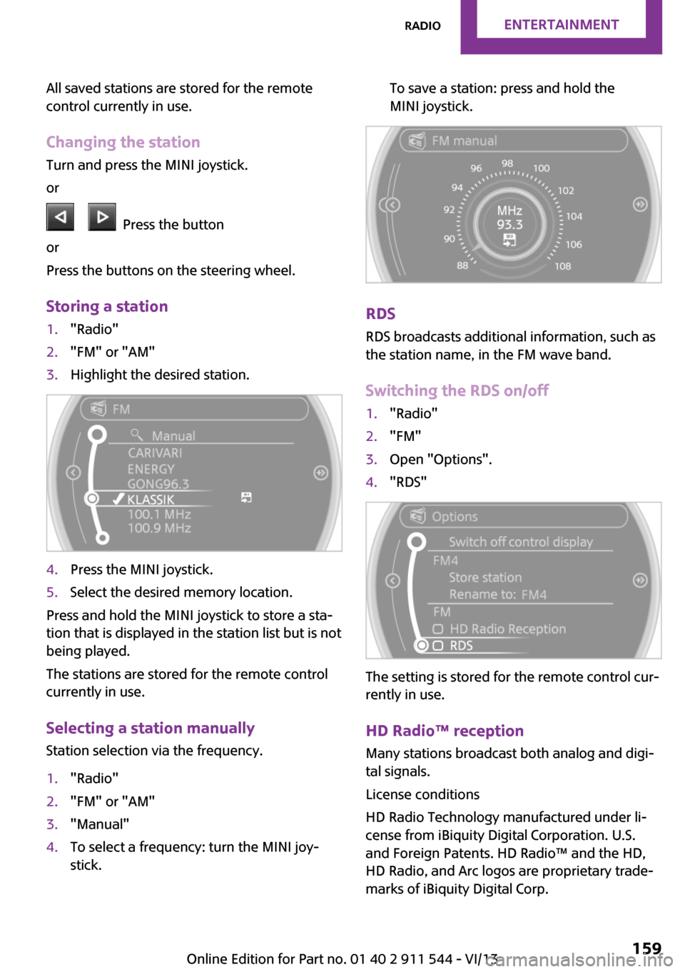
1."Radio"2."FM" or "AM"3.Highlight the desired station.4.Press the MINI joystick.5.Select the desired memory location.
Press and hold the MINI joystick to store a sta‐
tion that is displayed in the station list but is not
being played.
The stations are stored for the remote control
currently in use.
Selecting a station manually Station selection via the frequency.
1."Radio"2."FM" or "AM"3."Manual"4.To select a frequency: turn the MINI joy‐
stick.To save a station: press and hold the
MINI joystick.
RDS
RDS broadcasts additional information, such as
the station name, in the FM wave band.
Switching the RDS on/off
1."Radio"2."FM"3.Open "Options".4."RDS"
The setting is stored for the remote control cur‐
rently in use.
HD Radio™ reception
Many stations broadcast both analog and digi‐
tal signals.
License conditions
HD Radio Technology manufactured under li‐
cense from iBiquity Digital Corporation. U.S.
and Foreign Patents. HD Radio™ and the HD,
HD Radio, and Arc logos are proprietary trade‐
marks of iBiquity Digital Corp.
Seite 159RadioEntertainment159
Online Edition for Part no. 01 40 2 911 544 - VI/13
Page 183 of 282
▷A multi-character passkey may be needed.▷Did it take longer than 30 seconds to enter
the passkey? Repeat the pairing procedure.▷Are too many Bluetooth devices connected
to the mobile phone or vehicle? Delete con‐
nections with other devices if necessary.▷The mobile phone is in power-save mode
or has only a limited remaining battery life.
Charge the mobile phone via the charging
cable.▷Depending on the mobile phone, it is possi‐
ble that only one mobile phone can be con‐
nected to the vehicle. Unpair the connected
mobile phone from the vehicle and pair
and connect only one mobile phone.
The mobile phone no longer reacts.
▷Switch the mobile phone off and on again.▷Is the ambient temperature too high or
low? Do not expose the mobile phone to
extreme environmental conditions.
No phone book entries or only some phone
book entries are displayed, or they are incom‐
plete.
▷Transmission of the phone book entries is
not yet complete.▷It is possible that only the phone book en‐
tries of the mobile phone or the SIM card
are transmitted.▷It may not be possible to display phone
book entries with special characters.▷The number of phone book entries to be
stored is too high.▷Is the data volume of the contact too large,
e. g., due to stored information such as
notes? Reduce the data volume of the con‐
tact.
The phone connection quality is poor.
▷The strength of the Bluetooth signal on the
mobile phone can be adjusted, depending
on the mobile phone.▷Place the mobile phone in the area of the
center console.If all points in this list have been checked and
the required function is still not available, con‐
tact Customer Relations or the service center.
Controls Adjusting the volume
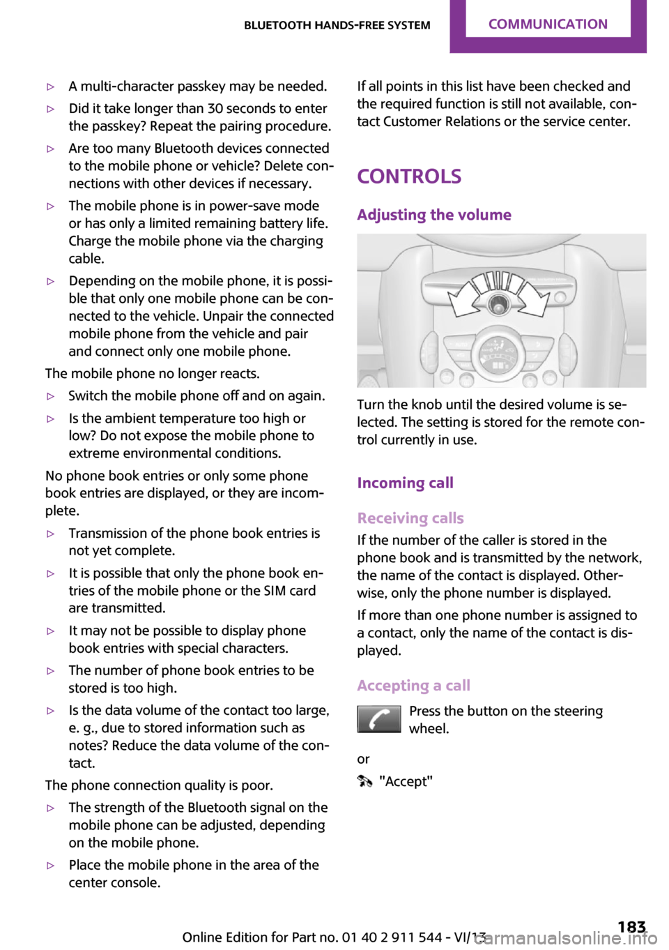
Turn the knob until the desired volume is se‐
lected. The setting is stored for the remote con‐
trol currently in use.
Incoming call
Receiving calls If the number of the caller is stored in the
phone book and is transmitted by the network,
the name of the contact is displayed. Other‐
wise, only the phone number is displayed.
If more than one phone number is assigned to
a contact, only the name of the contact is dis‐
played.
Accepting a call Press the button on the steering
wheel.
or
"Accept"
Seite 183Bluetooth hands-free systemCommunication183
Online Edition for Part no. 01 40 2 911 544 - VI/13
Page 195 of 282
The mobile phone no longer reacts.▷Switch the mobile phone off and on again.▷Is the ambient temperature too high or
low? Do not expose the mobile phone to
extreme environmental conditions.
The telephone functions are not available.
▷Is the mobile phone paired as an additional
telephone and is the additional telephone
function deactivated? Activate the function.▷Is an outgoing call not possible? Connect
the mobile phone as a telephone.
No phone book entries or only some phone
book entries are displayed, or they are incom‐
plete.
▷Transmission of the phone book entries is
not yet complete.▷It is possible that only the phone book en‐
tries of the mobile phone or the SIM card
are transmitted.▷It may not be possible to display phone
book entries with special characters.▷The number of phone book entries to be
stored is too high.▷Is the data volume of the contact too large,
e. g., due to stored information such as
notes? Reduce the data volume of the con‐
tact.▷Is the mobile phone connected as an audio
source or additional telephone? The mobile
phone must be connected as a telephone.
The phone connection quality is poor.
▷The strength of the Bluetooth signal on the
mobile phone can be adjusted, depending
on the mobile phone.▷Insert the mobile phone into the snap-in
adapter or place it in the area of the center
console.▷Adjust the volume of the microphone and
loudspeakers separately.
If all points in this list have been checked and
the required function is still not available, con‐
tact Customer Relations or the service center.
Controls
Adjusting the volume
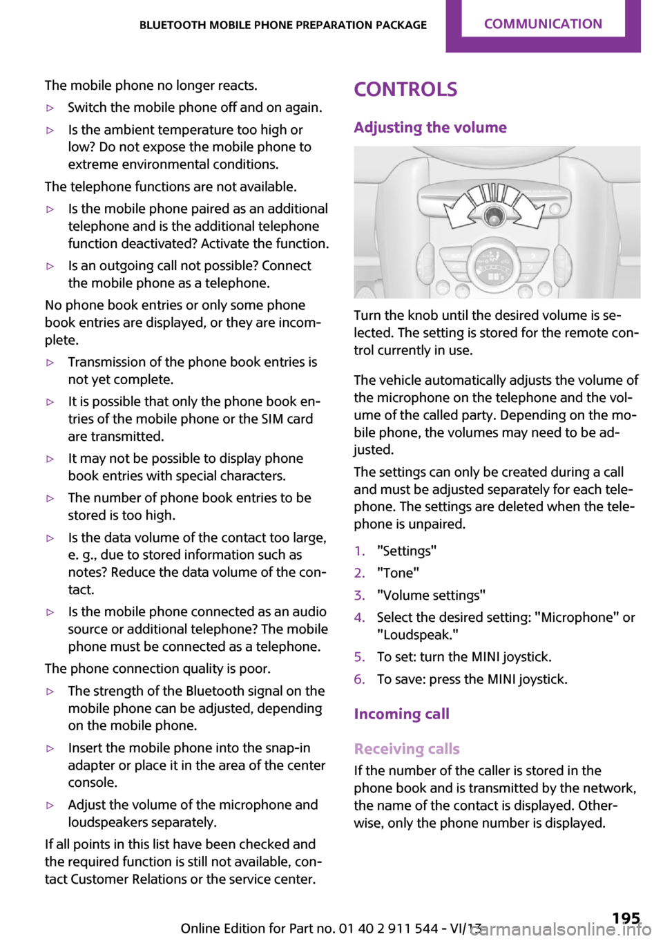
Turn the knob until the desired volume is se‐
lected. The setting is stored for the remote con‐
trol currently in use.
The vehicle automatically adjusts the volume of
the microphone on the telephone and the vol‐
ume of the called party. Depending on the mo‐
bile phone, the volumes may need to be ad‐
justed.
The settings can only be created during a call
and must be adjusted separately for each tele‐
phone. The settings are deleted when the tele‐
phone is unpaired.
1."Settings"2."Tone"3."Volume settings"4.Select the desired setting: "Microphone" or
"Loudspeak."5.To set: turn the MINI joystick.6.To save: press the MINI joystick.
Incoming call
Receiving calls If the number of the caller is stored in the
phone book and is transmitted by the network,
the name of the contact is displayed. Other‐
wise, only the phone number is displayed.
Seite 195Bluetooth mobile phone preparation packageCommunication195
Online Edition for Part no. 01 40 2 911 544 - VI/13
Page 197 of 282
If a second call comes in during an ongoing call,
a call waiting signal is sounded.
"Accept"
The call is accepted and the existing call is put
on hold.
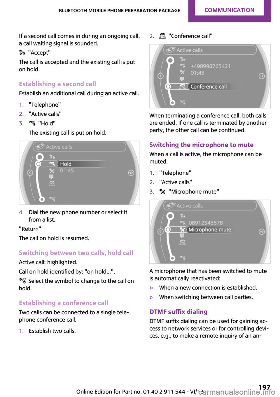
Establishing a second call Establish an additional call during an active call.
1."Telephone"2."Active calls"3. "Hold"
The existing call is put on hold.4.Dial the new phone number or select it
from a list.
"Return"
The call on hold is resumed.
Switching between two calls, hold call Active call: highlighted.
Call on hold identified by: "on hold...".
Select the symbol to change to the call on
hold.
Establishing a conference call
Two calls can be connected to a single tele‐
phone conference call.
1.Establish two calls.2. "Conference call"
When terminating a conference call, both calls
are ended. If one call is terminated by another
party, the other call can be continued.
Switching the microphone to mute When a call is active, the microphone can be
muted.
1."Telephone"2."Active calls"3. "Microphone mute"
A microphone that has been switched to mute
is automatically reactivated:
▷When a new connection is established.▷When switching between call parties.
DTMF suffix dialing
DTMF suffix dialing can be used for gaining ac‐
cess to network services or for controlling devi‐
ces, e.g., to make a remote inquiry of an an‐
Seite 197Bluetooth mobile phone preparation packageCommunication197
Online Edition for Part no. 01 40 2 911 544 - VI/13
Page 241 of 282
Due to the high voltage present in the system,
there is the danger of fatal injuries if work is
carried out improperly. ◀
Front lamps, bulb replacement
Halogen low beams and high beams
Bulb H13, 60/55 watt
Wear protective goggles and gloves
Halogen bulbs are pressurized. Therefore,
wear protective goggles and gloves. Otherwise,
there is a danger of injuries if the bulb is acci‐
dentally damaged during replacement. ◀
Attach the cover carefully
When attaching the cover, proceed care‐
fully; otherwise, leaks may occur, causing dam‐
age to the headlamp system. ◀
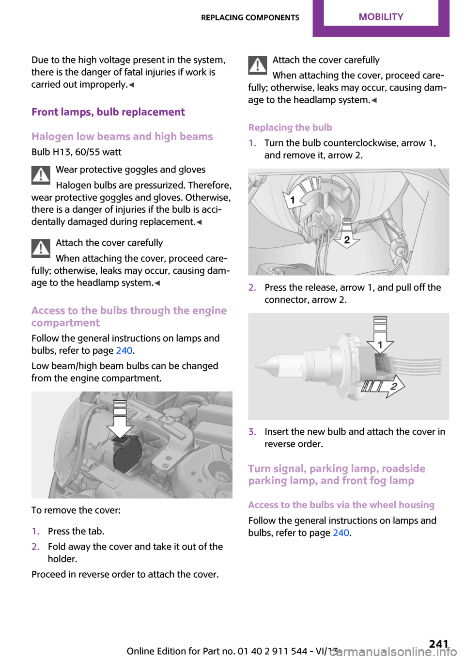
Access to the bulbs through the engine compartment
Follow the general instructions on lamps and
bulbs, refer to page 240.
Low beam/high beam bulbs can be changed
from the engine compartment.
To remove the cover:
1.Press the tab.2.Fold away the cover and take it out of the
holder.
Proceed in reverse order to attach the cover.
Attach the cover carefully
When attaching the cover, proceed care‐
fully; otherwise, leaks may occur, causing dam‐
age to the headlamp system. ◀
Replacing the bulb1.Turn the bulb counterclockwise, arrow 1,
and remove it, arrow 2.2.Press the release, arrow 1, and pull off the
connector, arrow 2.3.Insert the new bulb and attach the cover in
reverse order.
Turn signal, parking lamp, roadside
parking lamp, and front fog lamp
Access to the bulbs via the wheel housing
Follow the general instructions on lamps and
bulbs, refer to page 240.
Seite 241Replacing componentsMobility241
Online Edition for Part no. 01 40 2 911 544 - VI/13
Page 242 of 282

1Turn signal2Parking lamp/roadside parking lamp/fog
lamp
Replacing the turn signal bulb
21-watt bulb, P 21 W, or PY 21 W
1.Turn the wheel.2.Remove cover 1.
To do this, turn the cover counterclockwise.3.Remove the inside cover. To do this, turn
the cover counterclockwise.4.Turn the bulb counterclockwise and re‐
move it.5.Insert the new bulb and attach the covers
in reverse order.Replacing the parking lamp bulb and
roadside parking lamp bulb
5-watt bulb, W 5 W1.Turn the wheel.2.Remove cover 2.
To do this, turn the cover counterclockwise.3.Turn the upper bulb counterclockwise and
remove it.4.Insert the new bulb and attach the cover in
reverse order.
Replacing the front fog lamp bulb
H8 bulb, 35 watt
1.Turn the wheel.2.Remove cover 2.
To do this, turn the cover counterclockwise.3.Pull off the plug-in cable connector.4.Turn the lower bulb counterclockwise and
remove it.5.Insert the new bulb and attach the cover in
reverse order.Seite 242MobilityReplacing components242
Online Edition for Part no. 01 40 2 911 544 - VI/13
Page 243 of 282
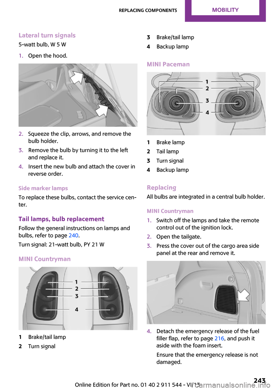
Lateral turn signals
5-watt bulb, W 5 W1.Open the hood.2.Squeeze the clip, arrows, and remove the
bulb holder.3.Remove the bulb by turning it to the left
and replace it.4.Insert the new bulb and attach the cover in
reverse order.
Side marker lamps
To replace these bulbs, contact the service cen‐
ter.
Tail lamps, bulb replacement Follow the general instructions on lamps and
bulbs, refer to page 240.
Turn signal: 21-watt bulb, PY 21 W
MINI Countryman
1Brake/tail lamp2Turn signal3Brake/tail lamp4Backup lamp
MINI Paceman
1Brake lamp2Tail lamp3Turn signal4Backup lamp
Replacing
All bulbs are integrated in a central bulb holder.
MINI Countryman
1.Switch off the lamps and take the remote
control out of the ignition lock.2.Open the tailgate.3.Press the cover out of the cargo area side
panel at the rear and remove it.4.Detach the emergency release of the fuel
filler flap, refer to page 216, and push it
aside with the foam insert.
Ensure that the emergency release is not
damaged.Seite 243Replacing componentsMobility243
Online Edition for Part no. 01 40 2 911 544 - VI/13
Page 251 of 282
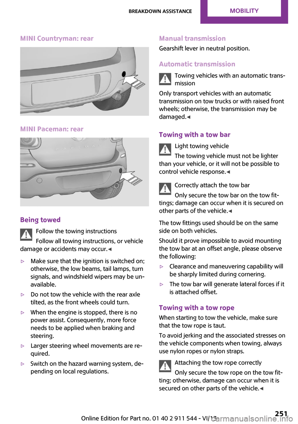
MINI Countryman: rear
MINI Paceman: rear
Being towedFollow the towing instructions
Follow all towing instructions, or vehicle
damage or accidents may occur. ◀
▷Make sure that the ignition is switched on;
otherwise, the low beams, tail lamps, turn
signals, and windshield wipers may be un‐
available.▷Do not tow the vehicle with the rear axle
tilted, as the front wheels could turn.▷When the engine is stopped, there is no
power assist. Consequently, more force
needs to be applied when braking and
steering.▷Larger steering wheel movements are re‐
quired.▷Switch on the hazard warning system, de‐
pending on local regulations.Manual transmission
Gearshift lever in neutral position.
Automatic transmission Towing vehicles with an automatic trans‐
mission
Only transport vehicles with an automatic
transmission on tow trucks or with raised front
wheels; otherwise, the transmission may be
damaged. ◀
Towing with a tow bar Light towing vehicle
The towing vehicle must not be lighter
than your vehicle, or it will not be possible to
control vehicle response. ◀
Correctly attach the tow bar
Only secure the tow bar on the tow fit‐
tings; damage can occur when it is secured on
other parts of the vehicle. ◀
The tow fittings used should be on the same
side on both vehicles.
Should it prove impossible to avoid mounting
the tow bar at an offset angle, please observe
the following:▷Clearance and maneuvering capability will
be sharply limited during cornering.▷The tow bar will generate lateral forces if it
is attached offset.
Towing with a tow rope
When starting to tow the vehicle, make sure
that the tow rope is taut.
To avoid jerking and the associated stresses on
the vehicle components when towing, always
use nylon ropes or nylon straps.
Attaching the tow rope correctly
Only secure the tow rope on the tow fit‐
ting; otherwise, damage can occur when it is
secured on other parts of the vehicle. ◀
Seite 251Breakdown assistanceMobility251
Online Edition for Part no. 01 40 2 911 544 - VI/13
Page 271 of 282
Bluetooth connection, activat‐ing/deactivating 181, 191
Bluetooth hands-free sys‐ tem 180
Brake assistant 93
Brake discs, breaking in 122
Brake fluid, refer to Service re‐ quirements 74
Brake force distribution, elec‐ tronic 93
Brake pads, breaking in 122
Brakes– Handbrake 60
Brakes, MINI maintenance
system 237
Brakes, service require‐ ments 74
Brake system, MINI mainte‐ nance system 237
Braking, notes 123
Breakdown assistance, Road‐ side Assistance 248
Breaking in 122
Brightness on the Control Dis‐ play 74
Buckle tongue, rear
– Height adjustment 48
Button for starting the engine,
refer to Start/Stop button 58
C
Calendar 206
California Proposition 65 Warning 7
Car battery, refer to Vehicle battery 246
Car care products 255
Care, displays 257
Care, vehicle 255
Cargo area
– Comfort Access 39– Flat loading floor 111– Multi-function hook 113– Opening from the out‐
side 37– Partition net 112Cargo area, enlarging– Cargo cover 110
Cargo area lamp, refer to Inte‐
rior lamps 81
Cargo area tailgate, refer to Tailgate 37
Car horn, refer to Horn 14
Carpet, care 257
Car phone, refer to Tele‐ phone 180, 190
Car wash 254
CBC, Cornering Brake Con‐
trol 93
CBS Condition Based Serv‐ ice 237
CD 166
CD/DVD drives, care 257
CD player 166
Center armrest 115
Center console, refer to Around the center con‐
sole 18
Center rail 116
Center rail, refer to Storage compartments 116
Central locking
– Comfort Access 38– From the inside 36– From the outside 34
Central locking system
– Concept 33– From the outside 33
Central screen, see Control
Display 20
Changes, technical, refer to Safety 7
Changing wheels/tires 227
Check Control 75
Children, transporting 53
Child restraint fixing system LATCH 54
Child restraint fixing sys‐ tems 53
Child restraint fixing systems, mounting 53
Child seat, mounting 53
Child seats, refer to Transport‐
ing children safely 53
Chrome parts, care 257
Circulation of air, refer to Re‐ circulated air
mode 100, 102
Cleaning, displays 257
Cleaning, refer to Care 254
Climate 99
Climate mode– Ventilation 103
Clock 68
Clock
– 12h/24h format 72– Setting the time and date 72
Closing
– From the inside 36– From the outside 34
Clutch, breaking in 122
Cockpit 14
Cold start, refer to Starting the engine 59
Combination instrument, refer to Displays 16
Combination switch, refer to Turn signal/high beams/
headlamp flasher 61
Combination switch, refer to Washer/wiper system 61
Comfort Access
– In the car wash 40– Replacing the battery 41
Comfort area, refer to Around
the center console 18
Compartment for remote con‐ trol, refer to Ignition lock 58
Compass, digital 106
Computer 69
Computer, displaying informa‐ tion 69
Condition Based Service CBS 237
Confirmation signals for vehi‐ cle locking/unlocking 35
Connecting, mobile phone, re‐ fer to Pairing the mobile
phone 180, 191
Seite 271Everything from A to ZReference271
Online Edition for Part no. 01 40 2 911 544 - VI/13
Page 272 of 282
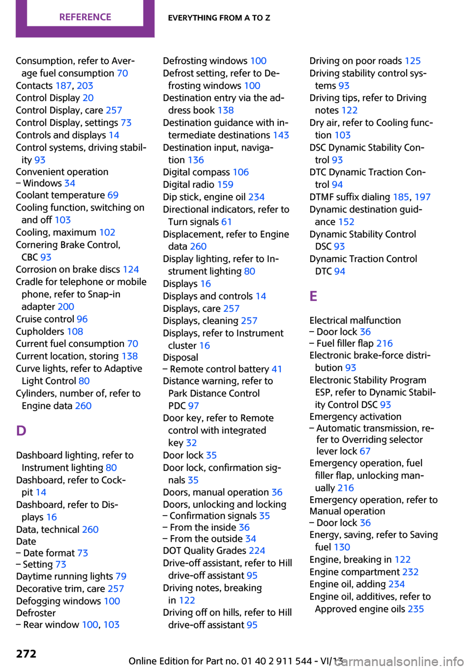
Consumption, refer to Aver‐age fuel consumption 70
Contacts 187, 203
Control Display 20
Control Display, care 257
Control Display, settings 73
Controls and displays 14
Control systems, driving stabil‐ ity 93
Convenient operation– Windows 34
Coolant temperature 69
Cooling function, switching on and off 103
Cooling, maximum 102
Cornering Brake Control, CBC 93
Corrosion on brake discs 124
Cradle for telephone or mobile phone, refer to Snap-in
adapter 200
Cruise control 96
Cupholders 108
Current fuel consumption 70
Current location, storing 138
Curve lights, refer to Adaptive Light Control 80
Cylinders, number of, refer to Engine data 260
D
Dashboard lighting, refer to Instrument lighting 80
Dashboard, refer to Cock‐ pit 14
Dashboard, refer to Dis‐ plays 16
Data, technical 260
Date
– Date format 73– Setting 73
Daytime running lights 79
Decorative trim, care 257
Defogging windows 100
Defroster
– Rear window 100, 103Defrosting windows 100
Defrost setting, refer to De‐ frosting windows 100
Destination entry via the ad‐ dress book 138
Destination guidance with in‐ termediate destinations 143
Destination input, naviga‐ tion 136
Digital compass 106
Digital radio 159
Dip stick, engine oil 234
Directional indicators, refer to Turn signals 61
Displacement, refer to Engine data 260
Display lighting, refer to In‐ strument lighting 80
Displays 16
Displays and controls 14
Displays, care 257
Displays, cleaning 257
Displays, refer to Instrument cluster 16
Disposal– Remote control battery 41
Distance warning, refer to
Park Distance Control
PDC 97
Door key, refer to Remote control with integrated
key 32
Door lock 35
Door lock, confirmation sig‐ nals 35
Doors, manual operation 36
Doors, unlocking and locking
– Confirmation signals 35– From the inside 36– From the outside 34
DOT Quality Grades 224
Drive-off assistant, refer to Hill drive-off assistant 95
Driving notes, breaking in 122
Driving off on hills, refer to Hill drive-off assistant 95
Driving on poor roads 125
Driving stability control sys‐ tems 93
Driving tips, refer to Driving notes 122
Dry air, refer to Cooling func‐ tion 103
DSC Dynamic Stability Con‐ trol 93
DTC Dynamic Traction Con‐ trol 94
DTMF suffix dialing 185, 197
Dynamic destination guid‐ ance 152
Dynamic Stability Control DSC 93
Dynamic Traction Control DTC 94
E Electrical malfunction– Door lock 36– Fuel filler flap 216
Electronic brake-force distri‐
bution 93
Electronic Stability Program ESP, refer to Dynamic Stabil‐
ity Control DSC 93
Emergency activation
– Automatic transmission, re‐
fer to Overriding selector
lever lock 67
Emergency operation, fuel
filler flap, unlocking man‐
ually 216
Emergency operation, refer to
Manual operation
– Door lock 36
Energy, saving, refer to Saving
fuel 130
Engine, breaking in 122
Engine compartment 232
Engine oil, adding 234
Engine oil, additives, refer to Approved engine oils 235
Seite 272ReferenceEverything from A to Z272
Online Edition for Part no. 01 40 2 911 544 - VI/13