remote control MINI Paceman 2014 (Mini Connected) Owner's Guide
[x] Cancel search | Manufacturer: MINI, Model Year: 2014, Model line: Paceman, Model: MINI Paceman 2014Pages: 282, PDF Size: 6.76 MB
Page 80 of 282
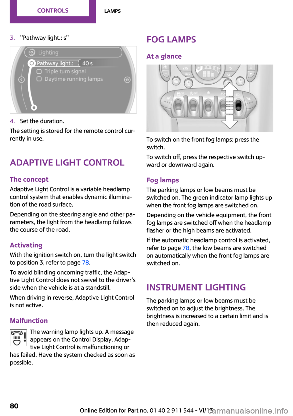
3."Pathway light.: s"4.Set the duration.
The setting is stored for the remote control cur‐
rently in use.
Adaptive Light Control
The concept
Adaptive Light Control is a variable headlamp
control system that enables dynamic illumina‐
tion of the road surface.
Depending on the steering angle and other pa‐
rameters, the light from the headlamp follows
the course of the road.
Activating
With the ignition switch on, turn the light switch
to position 3, refer to page 78.
To avoid blinding oncoming traffic, the Adap‐
tive Light Control does not swivel to the driver's
side when the vehicle is at a standstill.
When driving in reverse, Adaptive Light Control
is not active.
Malfunction The warning lamp lights up. A message
appears on the Control Display. Adap‐
tive Light Control is malfunctioning or
has failed. Have the system checked as soon as
possible.
Fog lamps
At a glance
To switch on the front fog lamps: press the
switch.
To switch off, press the respective switch up‐
ward or downward again.
Fog lamps
The parking lamps or low beams must be
switched on. The green indicator lamp lights up
when the front fog lamps are switched on.
Depending on the vehicle equipment, the front
fog lamps are switched off when the headlamp
flasher or the high beams are activated.
If the automatic headlamp control is activated,
refer to page 78, the low beams are switched
on automatically when the front fog lamps are
switched on.
Instrument lightingThe parking lamps or low beams must be
switched on to adjust the brightness. The
brightness is increased to a certain limit and is
then reduced again.
Seite 80ControlsLamps80
Online Edition for Part no. 01 40 2 911 544 - VI/13
Page 101 of 282
Microfilter
The microfilter traps dust and pollen. The mi‐
crofilter is changed by the service center during
routine maintenance work.
Microfilter/activated-charcoal filter
The microfilter traps dust and pollen. The acti‐
vated-charcoal filter provides additional protec‐tion by filtering gaseous pollutants from the
outside air. The service center replaces this
combined filter during routine maintenance.
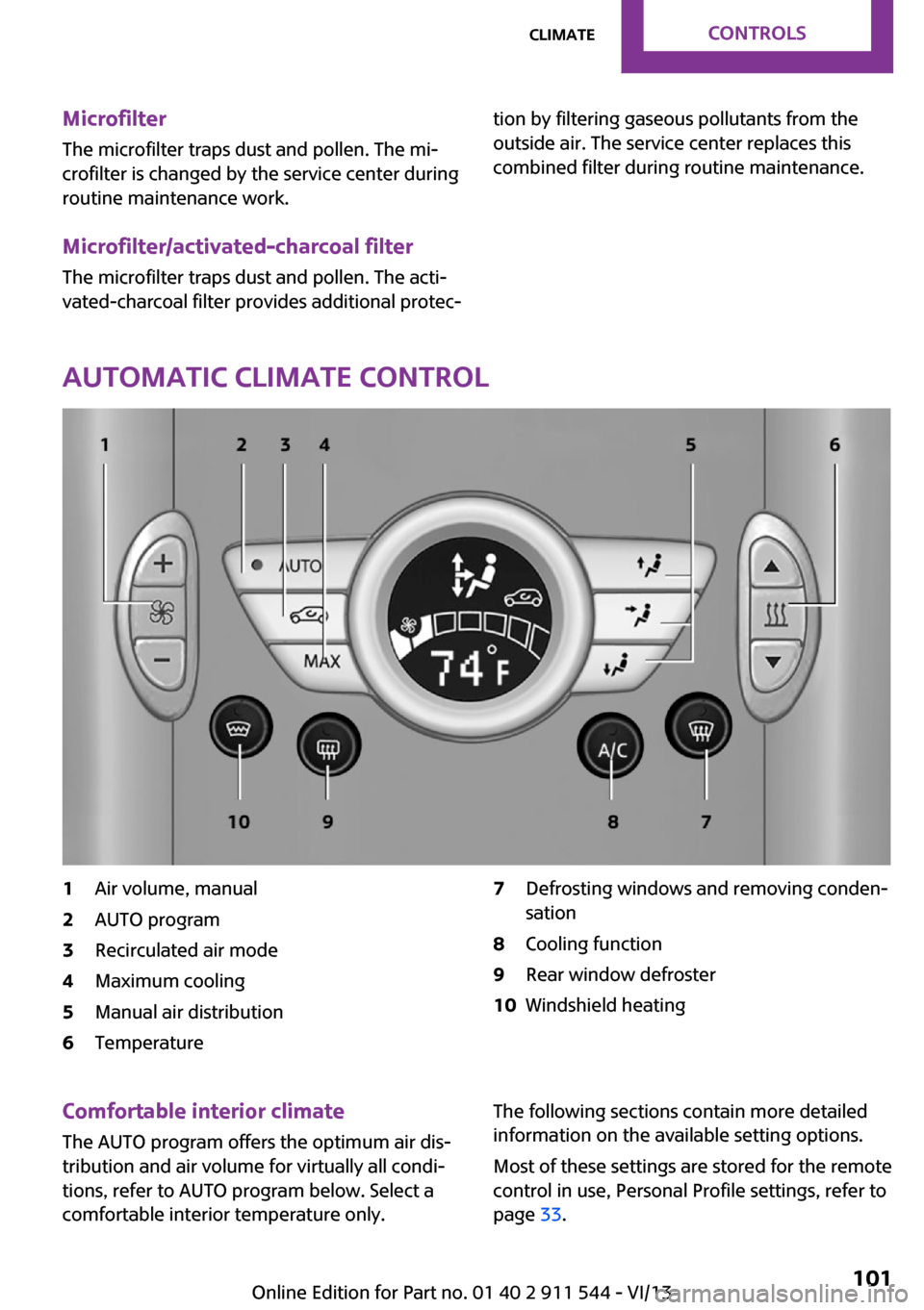
Automatic climate control
1Air volume, manual2AUTO program3Recirculated air mode4Maximum cooling5Manual air distribution6Temperature7Defrosting windows and removing conden‐
sation8Cooling function9Rear window defroster10Windshield heatingComfortable interior climate
The AUTO program offers the optimum air dis‐tribution and air volume for virtually all condi‐
tions, refer to AUTO program below. Select a
comfortable interior temperature only.The following sections contain more detailed
information on the available setting options.
Most of these settings are stored for the remote
control in use, Personal Profile settings, refer to
page 33.Seite 101ClimateControls101
Online Edition for Part no. 01 40 2 911 544 - VI/13
Page 104 of 282
Interior equipmentVehicle equipmentThis chapter describes all series equipment as
well as country-specific and special equipment
offered for this model series.Therefore, it also
describes equipment that may not be found in
your vehicle, for instance due to the selected
special equipment or the country version. This
also applies to safety-related functions and sys‐
tems.
Universal garage door
opener
The concept
The universal garage door opener can be used
to operate up to 3 functions in remote-control‐
led systems, such as garage door drives or
lighting systems. The universal garage door
opener replaces up to 3 different hand-held
transmitters. To operate it, the buttons on the
interior rearview mirror must be programmed
for the desired functions. The hand-held trans‐
mitter for the system is needed for the pro‐
gramming procedure.
During programming
During programming and before activat‐
ing a device using the Universal Garage Door
Opener, ensure that there are no people, ani‐
mals, or objects in the range of movement of
the remote-controlled device; otherwise, there
is a risk of injury or damage.
Also follow the safety instructions of the hand-
held transmitter. ◀
Before selling the vehicle, delete the stored
functions for security reasons.Compatibility
If this symbol is printed on the packag‐
ing or in the operating instructions of
the system being operated, the system
is generally compatible with the universal ga‐
rage door opener.
If you have any questions, please contact:▷Your service center.▷www.homelink.com on the Internet.
HomeLink is a registered trademark of Johnson
Controls, Inc.
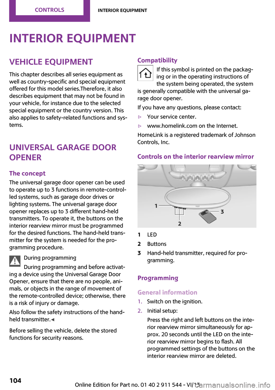
Controls on the interior rearview mirror
1LED2Buttons3Hand-held transmitter, required for pro‐
gramming.
Programming
General information
1.Switch on the ignition.2.Initial setup:
Press the right and left buttons on the inte‐
rior rearview mirror simultaneously for ap‐
prox. 20 seconds until the LED on the inte‐
rior rearview mirror begins to flash. All
programmed settings of the buttons on the
interior rearview mirror are deleted.Seite 104ControlsInterior equipment104
Online Edition for Part no. 01 40 2 911 544 - VI/13
Page 108 of 282
Cupholders and ashtray/
lighter
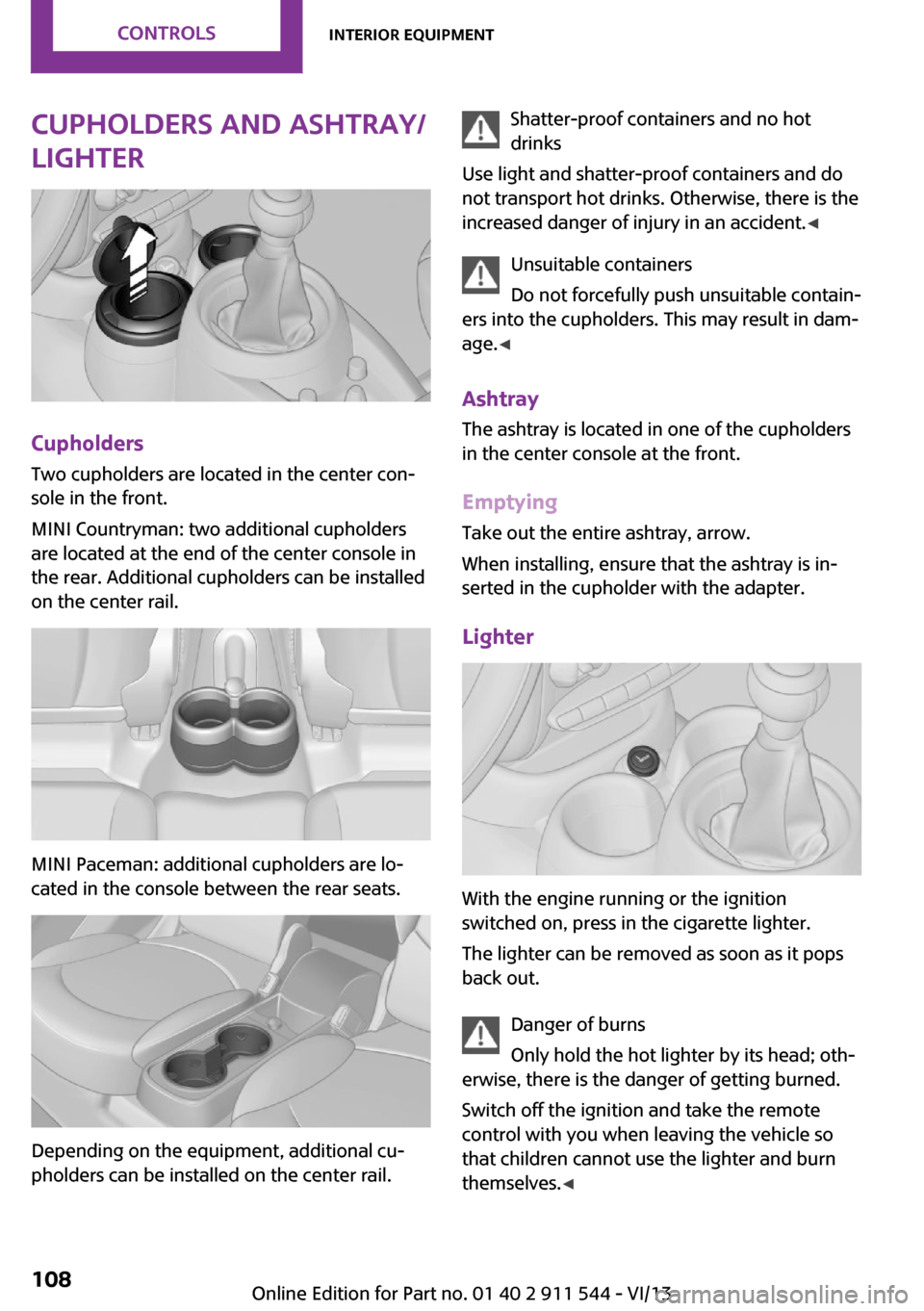
Cupholders
Two cupholders are located in the center con‐
sole in the front.
MINI Countryman: two additional cupholders
are located at the end of the center console in
the rear. Additional cupholders can be installed
on the center rail.
MINI Paceman: additional cupholders are lo‐
cated in the console between the rear seats.
Depending on the equipment, additional cu‐
pholders can be installed on the center rail.
Shatter-proof containers and no hot
drinks
Use light and shatter-proof containers and do
not transport hot drinks. Otherwise, there is the
increased danger of injury in an accident. ◀
Unsuitable containers
Do not forcefully push unsuitable contain‐
ers into the cupholders. This may result in dam‐
age. ◀
Ashtray The ashtray is located in one of the cupholders
in the center console at the front.
Emptying Take out the entire ashtray, arrow.
When installing, ensure that the ashtray is in‐
serted in the cupholder with the adapter.
Lighter
With the engine running or the ignition
switched on, press in the cigarette lighter.
The lighter can be removed as soon as it pops
back out.
Danger of burns
Only hold the hot lighter by its head; oth‐
erwise, there is the danger of getting burned.
Switch off the ignition and take the remote
control with you when leaving the vehicle so
that children cannot use the lighter and burn
themselves. ◀
Seite 108ControlsInterior equipment108
Online Edition for Part no. 01 40 2 911 544 - VI/13
Page 145 of 282
Destination guidanceVehicle equipmentThis chapter describes all series equipment as
well as country-specific and special equipment
offered for this model series.Therefore, it also
describes equipment that may not be found in
your vehicle, for instance due to the selected
special equipment or the country version. This
also applies to safety-related functions and sys‐
tems.
Starting destination
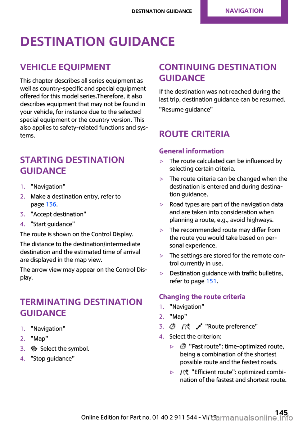
guidance1."Navigation"2.Make a destination entry, refer to
page 136.3."Accept destination"4."Start guidance"
The route is shown on the Control Display.
The distance to the destination/intermediate
destination and the estimated time of arrival
are displayed in the map view.
The arrow view may appear on the Control Dis‐
play.
Terminating destination
guidance
1."Navigation"2."Map"3. Select the symbol.4."Stop guidance"Continuing destination
guidance
If the destination was not reached during the
last trip, destination guidance can be resumed.
"Resume guidance"
Route criteria
General information▷The route calculated can be influenced by
selecting certain criteria.▷The route criteria can be changed when the
destination is entered and during destina‐
tion guidance.▷Road types are part of the navigation data
and are taken into consideration when
planning a route, e.g., avoid highways.▷The recommended route may differ from
the route you would take based on per‐
sonal experience.▷The settings are stored for the remote con‐
trol currently in use.▷Destination guidance with traffic bulletins,
refer to page 151.
Changing the route criteria
1."Navigation"2."Map"3. "Route preference"4.Select the criterion:▷ "Fast route": time-optimized route,
being a combination of the shortest
possible route and the fastest roads.▷ "Efficient route": optimized combi‐
nation of the fastest and shortest route.Seite 145Destination guidanceNavigation145
Online Edition for Part no. 01 40 2 911 544 - VI/13
Page 147 of 282
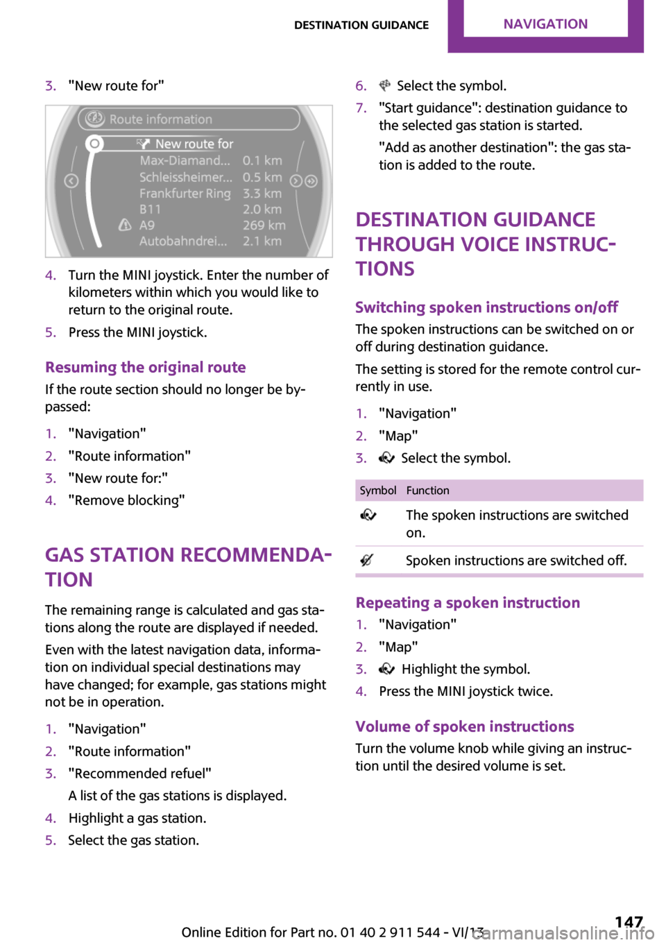
3."New route for"4.Turn the MINI joystick. Enter the number of
kilometers within which you would like to
return to the original route.5.Press the MINI joystick.
Resuming the original route
If the route section should no longer be by‐
passed:
1."Navigation"2."Route information"3."New route for:"4."Remove blocking"
Gas station recommenda‐
tion
The remaining range is calculated and gas sta‐
tions along the route are displayed if needed.
Even with the latest navigation data, informa‐
tion on individual special destinations may
have changed; for example, gas stations might
not be in operation.
1."Navigation"2."Route information"3."Recommended refuel"
A list of the gas stations is displayed.4.Highlight a gas station.5.Select the gas station.6. Select the symbol.7."Start guidance": destination guidance to
the selected gas station is started.
"Add as another destination": the gas sta‐
tion is added to the route.
Destination guidance
through voice instruc‐
tions
Switching spoken instructions on/off The spoken instructions can be switched on or
off during destination guidance.
The setting is stored for the remote control cur‐
rently in use.
1."Navigation"2."Map"3. Select the symbol.SymbolFunction The spoken instructions are switched
on. Spoken instructions are switched off.
Repeating a spoken instruction
1."Navigation"2."Map"3. Highlight the symbol.4.Press the MINI joystick twice.
Volume of spoken instructions
Turn the volume knob while giving an instruc‐
tion until the desired volume is set.
Seite 147Destination guidanceNavigation147
Online Edition for Part no. 01 40 2 911 544 - VI/13
Page 148 of 282
This volume is independent of the volume of
the audio sources.
The setting is stored for the remote control cur‐
rently in use.
Map view
Selecting the map view
1."Navigation"2."Map"
At a glance
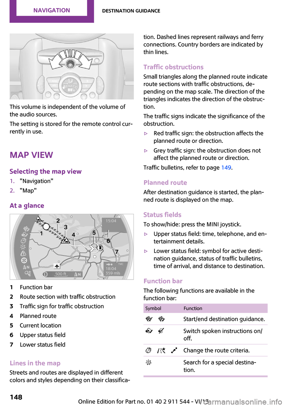
1Function bar2Route section with traffic obstruction3Traffic sign for traffic obstruction4Planned route5Current location6Upper status field7Lower status field
Lines in the map Streets and routes are displayed in different
colors and styles depending on their classifica‐
tion. Dashed lines represent railways and ferry
connections. Country borders are indicated by
thin lines.
Traffic obstructions
Small triangles along the planned route indicate
route sections with traffic obstructions, de‐
pending on the map scale. The direction of the
triangles indicates the direction of the obstruc‐
tion.
The traffic signs indicate the significance of the
obstruction.▷Red traffic sign: the obstruction affects the
planned route or direction.▷Grey traffic sign: the obstruction does not
affect the planned route or direction.
Traffic bulletins, refer to page 149.
Planned route After destination guidance is started, the plan‐
ned route is displayed on the map.
Status fields
To show/hide: press the MINI joystick.
▷Upper status field: time, telephone, and en‐
tertainment details.▷Lower status field: symbol for active desti‐
nation guidance, status of traffic bulletins,
time of arrival, and distance to destination.
Function bar
The following functions are available in the
function bar:
SymbolFunction Start/end destination guidance. Switch spoken instructions on/
off. Change the route criteria. Search for a special destina‐
tion.Seite 148NavigationDestination guidance148
Online Edition for Part no. 01 40 2 911 544 - VI/13
Page 149 of 282
SymbolFunction Display traffic bulletins. Open the interactive map. Adjust the map views. Adjust the arrow view. Change the scale.
Changing the map section
"Interactive map"
▷To shift the map: move the MINI joystick in
the required direction.▷To shift the map diagonally: move the
MINI joystick in the required direction and
turn the MINI joystick.
Changing the scale
1. Select the symbol.2.To change the scale: turn the MINI joystick.
Automatically scaled map scale
In the map view facing north, turn the MINI joy‐
stick in any direction until the AUTO is dis‐
played for the scale. The entire route between
the current location and the destination is dis‐
played on the map.
Settings for the map view
The settings are stored for the remote control
currently in use.
1."Navigation"2."Map"3.Open "Options".4."Settings"5.To set the map view:▷"Day/night mode"
Select and create the necessary settings
depending on the light conditions."Traffic conditions/gray map" active:
the setting is disregarded.▷"Traffic conditions/gray map"
The map is optimized for displaying
traffic bulletins.
Symbols for the special destinations are
no longer displayed.
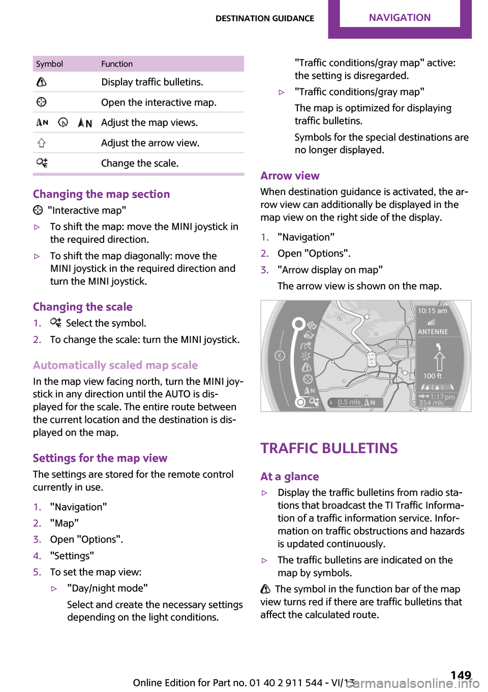
Arrow view
When destination guidance is activated, the ar‐
row view can additionally be displayed in the
map view on the right side of the display.
1."Navigation"2.Open "Options".3."Arrow display on map"
The arrow view is shown on the map.
Traffic bulletins
At a glance
▷Display the traffic bulletins from radio sta‐
tions that broadcast the TI Traffic Informa‐
tion of a traffic information service. Infor‐
mation on traffic obstructions and hazards
is updated continuously.▷The traffic bulletins are indicated on the
map by symbols.
The symbol in the function bar of the map
view turns red if there are traffic bulletins that
affect the calculated route.
Seite 149Destination guidanceNavigation149
Online Edition for Part no. 01 40 2 911 544 - VI/13
Page 156 of 282
ToneVehicle equipmentThis chapter describes all series equipment as
well as country-specific and special equipment
offered for this model series.Therefore, it also
describes equipment that may not be found in
your vehicle, for instance due to the selected
special equipment or the country version. This
also applies to safety-related functions and sys‐
tems.
General information The sound settings are stored for the remote
control currently in use.
Treble, bass, balance,
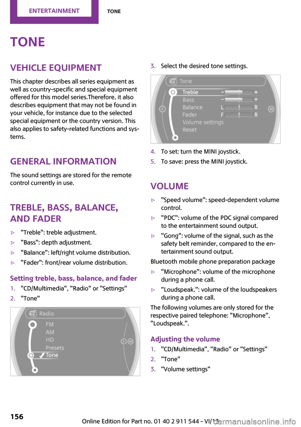
and fader▷"Treble": treble adjustment.▷"Bass": depth adjustment.▷"Balance": left/right volume distribution.▷"Fader": front/rear volume distribution.
Setting treble, bass, balance, and fader
1."CD/Multimedia", "Radio" or "Settings"2."Tone"3.Select the desired tone settings.4.To set: turn the MINI joystick.5.To save: press the MINI joystick.
Volume
▷"Speed volume": speed-dependent volume
control.▷"PDC": volume of the PDC signal compared
to the entertainment sound output.▷"Gong": volume of the signal, such as the
safety belt reminder, compared to the en‐
tertainment sound output.
Bluetooth mobile phone preparation package
▷"Microphone": volume of the microphone
during a phone call.▷"Loudspeak.": volume of the loudspeakers
during a phone call.
The following volumes are only stored for the
respective paired telephone: "Microphone",
"Loudspeak.".
Adjusting the volume
1."CD/Multimedia", "Radio" or "Settings"2."Tone"3."Volume settings"Seite 156EntertainmentTone156
Online Edition for Part no. 01 40 2 911 544 - VI/13
Page 159 of 282
All saved stations are stored for the remote
control currently in use.
Changing the station Turn and press the MINI joystick.
or
Press the button
or
Press the buttons on the steering wheel.
Storing a station
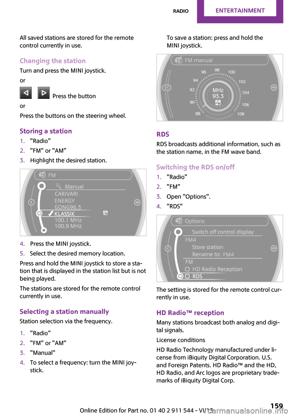
1."Radio"2."FM" or "AM"3.Highlight the desired station.4.Press the MINI joystick.5.Select the desired memory location.
Press and hold the MINI joystick to store a sta‐
tion that is displayed in the station list but is not
being played.
The stations are stored for the remote control
currently in use.
Selecting a station manually Station selection via the frequency.
1."Radio"2."FM" or "AM"3."Manual"4.To select a frequency: turn the MINI joy‐
stick.To save a station: press and hold the
MINI joystick.
RDS
RDS broadcasts additional information, such as
the station name, in the FM wave band.
Switching the RDS on/off
1."Radio"2."FM"3.Open "Options".4."RDS"
The setting is stored for the remote control cur‐
rently in use.
HD Radio™ reception
Many stations broadcast both analog and digi‐
tal signals.
License conditions
HD Radio Technology manufactured under li‐
cense from iBiquity Digital Corporation. U.S.
and Foreign Patents. HD Radio™ and the HD,
HD Radio, and Arc logos are proprietary trade‐
marks of iBiquity Digital Corp.
Seite 159RadioEntertainment159
Online Edition for Part no. 01 40 2 911 544 - VI/13