ESP MINI Paceman 2014 (Mini Connected) Service Manual
[x] Cancel search | Manufacturer: MINI, Model Year: 2014, Model line: Paceman, Model: MINI Paceman 2014Pages: 282, PDF Size: 6.76 MB
Page 225 of 282
Conform to Federal Safety Requirements
All passenger car tires must conform to
Federal Safety Requirements in addition to
these grades. ◀
Treadwear
The treadwear grade is a comparative rating based on the wear rate of the tire when tested
under controlled conditions on a specified gov‐
ernment test course. For example, a tire graded
150 would wear one and one-half (1 1/2) times
as well on the government course as a tire graded 100. The relative performance of tires
depends upon the actual conditions of their
use, however, and may depart significantly
from the norm due to variations in driving hab‐
its, service practices and differences in road
characteristics and climate.
TractionThe traction grades, from highest to lowest, are
AA, A, B, and C.
Those grades represent the tire’s ability to stop
on wet pavement as measured under control‐
led conditions on specified government test
surfaces of asphalt and concrete. A tire marked
C may have poor traction performance.
The traction grade assigned to this tire is based
on straight-ahead braking traction tests, and
does not include acceleration, cornering, hy‐
droplaning, or peak traction characteristics.
Temperature
The temperature grades are A, the highest, B,
and C, representing the tire’s resistance to the
generation of heat and its ability to dissipate
heat when tested under controlled conditions
on a specified indoor laboratory test wheel.
Sustained high temperature can cause the ma‐
terial of the tire to degenerate and reduce tire
life, and excessive temperature can lead to
sudden tire failure. The grade C corresponds to
a level of performance which all passenger car
tires must meet under the Federal Motor Vehi‐cle Safety Standard No. 109. Grades B and A
represent higher levels of performance on the
laboratory test wheel than the minimum re‐
quired by law.
Temperature grade for this tire
The temperature grade for this tire is es‐
tablished for a tire that is properly inflated and
not overloaded. Excessive speed, underinfla‐
tion, or excessive loading, either separately or
in combination, can cause heat buildup and
possible tire failure. ◀
RSC – Run-flat tires
The symbol identifying run-flat tires is a circle
with the letters RSC on the sidewall, refer to
page 228.
M+S
Winter and all-season tires.
These have better winter properties than
summer tires.
XL
Designation for specially reinforced tires.
Tire treadSummer tiresThe tread depth should not be less than
0.12 in/3 mm, although European legislation,
for example, requires a minimum tread depth
of only 0.063 in/1.6 mm. At tread depths less
than 0.12 in/3 mm, there is a great danger of
hydroplaning even in low water depths and at
raised speeds.
Winter tires
The suitability of winter tires for winter driving
is reduced noticeably when their tread depth
becomes less than 0.16 in/4 mm.Seite 225Wheels and tiresMobility225
Online Edition for Part no. 01 40 2 911 544 - VI/13
Page 227 of 282
Changing wheels and
tires
Mounting Information on mounting tires
Have mounting and balancing performed
only by a service center or tire specialist.
If this work is not carried out properly, there is
the danger of subsequent damage and related
safety hazards. ◀
Wheel and tire combination Information on the right wheel and tire combi‐
nation and rim version for your vehicle can be
obtained from the service center.
Incorrect wheel and tire combinations impair
the function of a variety of systems such as ABS
or DSC.
To maintain good handling and vehicle re‐
sponse, use only tires with a single tread con‐
figuration from a single manufacturer.
Following tire damage, have the original wheel
and tire combination remounted on the vehicle
as soon as possible.
Approved wheels and tires
The manufacturer of your vehicle recom‐
mends that you use only wheels and tires that
have been approved for your particular vehicle
model.
For example, despite having the same official
size ratings, variations can lead to body contact
and with it, the risk of severe accidents.
The manufacturer of your vehicle cannot evalu‐
ate non-approved wheels and tires to deter‐
mine if they are suited for use, and therefore
cannot ensure the operating safety of the vehi‐
cle if they are mounted. ◀Wheels with electronics for TPM Tire
Pressure Monitor
When mounting new tires or changing from
summer to winter tires or vice versa, only use
wheels with TPM electronics; otherwise, the
Tire Pressure Monitor will not be able to detect
a flat tire, refer to page 87. Your service center
will be glad to advise you.
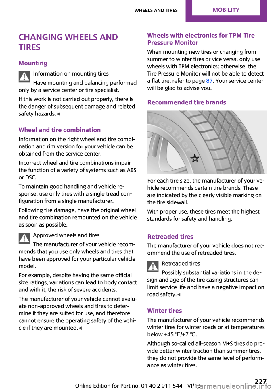
Recommended tire brands
For each tire size, the manufacturer of your ve‐
hicle recommends certain tire brands. These
are indicated by the clearly visible marking on
the tire sidewall.
With proper use, these tires meet the highest
standards for safety and handling.
Retreaded tires
The manufacturer of your vehicle does not rec‐
ommend the use of retreaded tires.
Retreaded tires
Possibly substantial variations in the de‐
sign and age of the tire casing structures can
limit service life and have a negative impact on
road safety. ◀
Winter tires The manufacturer of your vehicle recommends
winter tires for winter roads or at temperatures
below +45 ℉/+7 ℃.
Although so-called all-season M+S tires do pro‐
vide better winter traction than summer tires,
they do not provide the same level of perform‐
ance as winter tires.
Seite 227Wheels and tiresMobility227
Online Edition for Part no. 01 40 2 911 544 - VI/13
Page 228 of 282
Maximum speed of winter tires
If the maximum speed of the vehicle is higher
than the permissible speed for the winter tires,
then display a corresponding sign in the field of
vision. You can obtain this sign from the tire
specialist or from your service center.
Maximum speed for winter tires
Do not exceed the maximum speed for
the winter tires; otherwise, tire damage and ac‐
cidents can occur. ◀
Run-flat tires When mounting new tires or changing fromsummer to winter tires or vice versa, use run-
flat tires for your own safety. Also, a compact
wheel is not available in case of a flat tire. Your
service center will be glad to advise you.
Rotating wheels between axles
Different wear patterns occur on the front and
rear axles, depending on the individual condi‐
tions of use.
To ensure even wear on the tires, the wheels
can be rotated between the axles. Your service
center will be glad to advise you.
After changing the tires, check the tire inflation
pressure and correct it if necessary.
Storage Store wheels and tires in a cool, dry place with
as little exposure to light as possible.
Always protect tires against all contact with oil,
grease and fuels.
Do not exceed the maximum tire inflation pres‐
sure indicated on the side wall of the tire.Run-flat tires
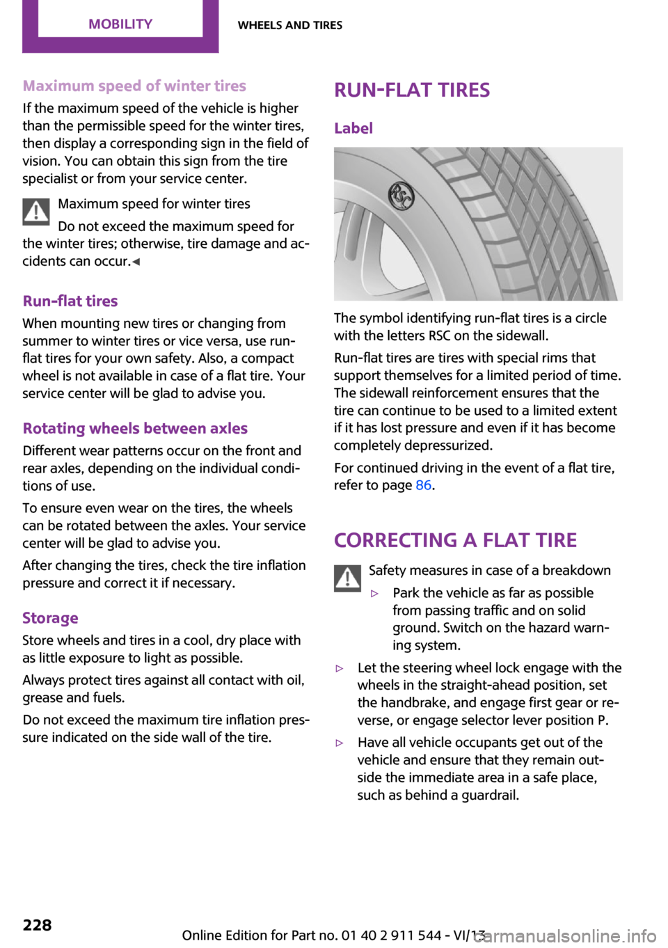
Label
The symbol identifying run-flat tires is a circle
with the letters RSC on the sidewall.
Run-flat tires are tires with special rims that
support themselves for a limited period of time.
The sidewall reinforcement ensures that the
tire can continue to be used to a limited extent
if it has lost pressure and even if it has become
completely depressurized.
For continued driving in the event of a flat tire,
refer to page 86.
Correcting a flat tire Safety measures in case of a breakdown
▷Park the vehicle as far as possible
from passing traffic and on solid
ground. Switch on the hazard warn‐
ing system.▷Let the steering wheel lock engage with the
wheels in the straight-ahead position, set
the handbrake, and engage first gear or re‐
verse, or engage selector lever position P.▷Have all vehicle occupants get out of the
vehicle and ensure that they remain out‐
side the immediate area in a safe place,
such as behind a guardrail.Seite 228MobilityWheels and tires228
Online Edition for Part no. 01 40 2 911 544 - VI/13
Page 234 of 282

Engine oilVehicle equipment
This chapter describes all series equipment as
well as country-specific and special equipment
offered for this model series.Therefore, it also
describes equipment that may not be found in
your vehicle, for instance due to the selected
special equipment or the country version. This
also applies to safety-related functions and sys‐
tems.
Engine oil General information
Engine oil consumption depends on the driving
style and the conditions of use. A highly sporty
driving style, for example, results in considera‐
bly higher engine oil consumption.
Therefore, regularly check the engine oil level
after refueling.
Checking the oil level with a dip stick1.Park the vehicle on level ground when the
engine is at operating temperature, i.e., af‐
ter driving continuously for at least
6 2 miles/10 km.2.Switch the engine off.3.After approx. 5 minutes, pull out the dip
stick and wipe it off with a lint-free cloth,
paper towel, etc.4.Carefully insert the dip stick all the way into
the measuring tube and pull it out again.The oil level must be between the two
marks on the dip stick.
The oil quantity between the two marks on the
dip stick equals approx. 1 US quart/1 liter.
Do not exceed the high mark.
Do not exceed the high mark of the dip
stick. Overfilling oil damages the engine. ◀
Adding engine oil
Filler neck
Add a maximum quantity of 1 US quart/1 liter
of oil only after the corresponding message ap‐
pears on the Control Display or, in diesel en‐
gines, after the oil level is just above the low
mark of the dip stick, refer to page 234.
Add oil promptly
Add oil within the next 30 miles/50 km;
otherwise, engine damage could result. ◀
Seite 234MobilityEngine oil234
Online Edition for Part no. 01 40 2 911 544 - VI/13
Page 240 of 282
Lamp and bulb replace‐
ment
Notes
Lamps and bulbs Lamps and bulbs make an essential contribu‐
tion to vehicle safety. Therefore, exercise cau‐
tion when handling lamps and bulbs.
The manufacturer of the vehicle recommends
that you entrust corresponding procedures to
the service center if you are unfamiliar with
them or they are not described here.
You can obtain a selection of replacement
bulbs at the service center.
Danger of burns
Only change bulbs when they are cool;
otherwise, there is the danger of getting
burned. ◀
Working on the lighting system
When working on the lighting system,
you should always switch off the lights affected
to prevent short circuits.
To avoid possible injury or equipment damage
when replacing bulbs, observe any instructions
provided by the bulb manufacturer. ◀
Do not touch the bulbs
Do not touch the glass of new bulbs with
your bare hands, as even minute amounts of
contamination will burn into the bulb's surface
and reduce its service life.
Use a clean tissue, cloth or something similar,
or hold the bulb by its base. ◀
Caring for the headlamps, refer to page 255.
For bulb replacement that is not described
here, please contact the service center or a
workshop that works according to the repair
procedures of the manufacturer with corre‐
spondingly trained personnel.For checking and adjusting headlamp aim,
please contact your MINI dealer.
Light-emitting diodes LEDs Light-emitting diodes installed behind translu‐
cent lenses serve as the light source for many
of the controls and displays in the vehicle.
These light-emitting diodes, which operate us‐
ing a concept similar to that applied in conven‐
tional lasers, are officially designated as Class 1
light-emitting diodes.
Do not remove the covers
Do not remove the covers, and never
stare into the unfiltered light for several hours;
otherwise, irritation of the retina could result. ◀
Headlamp glass
Condensation can form on the inside of the
headlamps in cool or humid weather. When the
light is switched on, the condensation evapo‐ rates after a short time. The headlamps do notneed to be changed.
If the condensation in the headlamps does not
evaporate after trips with the lights switched
on, and the amount of moisture in the head‐
lamps increases, for example if water droplets
form, have them checked by your service cen‐
ter.
Bi-xenon headlamps These bulbs have a very long life and the likeli‐
hood of failure is very low, provided that they
are not switched on and off excessively. If a
bulb should nevertheless fail, you can continue
driving cautiously with the front fog lamps, pro‐
vided this is permitted by local laws.
Do not perform work/bulb replacement
on xenon headlamps
Have any work on the xenon lighting system,
including bulb replacement, performed only by
a service center.Seite 240MobilityReplacing components240
Online Edition for Part no. 01 40 2 911 544 - VI/13
Page 245 of 282
Replacing
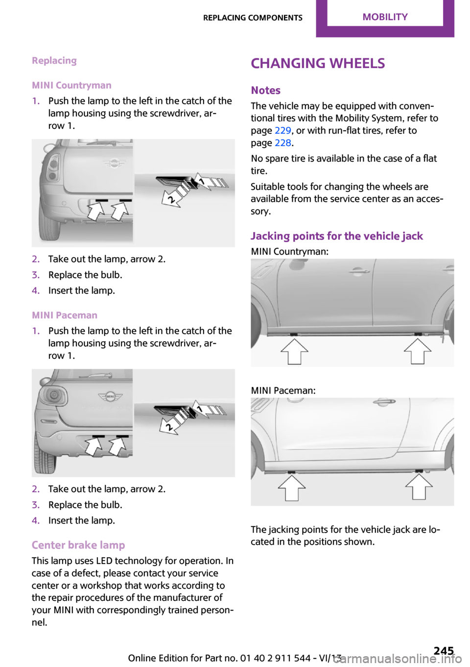
MINI Countryman1.Push the lamp to the left in the catch of the
lamp housing using the screwdriver, ar‐
row 1.2.Take out the lamp, arrow 2.3.Replace the bulb.4.Insert the lamp.
MINI Paceman
1.Push the lamp to the left in the catch of the
lamp housing using the screwdriver, ar‐
row 1.2.Take out the lamp, arrow 2.3.Replace the bulb.4.Insert the lamp.
Center brake lamp
This lamp uses LED technology for operation. In
case of a defect, please contact your service
center or a workshop that works according to
the repair procedures of the manufacturer of
your MINI with correspondingly trained person‐
nel.
Changing wheels
Notes
The vehicle may be equipped with conven‐
tional tires with the Mobility System, refer to
page 229, or with run-flat tires, refer to
page 228.
No spare tire is available in the case of a flat
tire.
Suitable tools for changing the wheels are
available from the service center as an acces‐
sory.
Jacking points for the vehicle jack MINI Countryman:
MINI Paceman:
The jacking points for the vehicle jack are lo‐
cated in the positions shown.
Seite 245Replacing componentsMobility245
Online Edition for Part no. 01 40 2 911 544 - VI/13
Page 249 of 282
Do not touch live parts
To avoid the risk of potentially fatal injury,
always avoid all contact with electrical compo‐
nents while the engine is running. ◀
Preparation1.Check whether the battery of the other ve‐
hicle has a voltage of 12 volts and approxi‐
mately the same capacitance in Ah. This in‐
formation can be found on the battery.2.Switch off the engine of the assisting vehi‐
cle.3.Switch off any electronic systems/power
consumers in both vehicles.
Bodywork contact between vehicles
There must not be any contact between
the bodies of the two vehicles, otherwise there
is a danger of shorting. ◀
Connecting jumper cables
Connecting order
Connect the jumper cables in the correct
order; otherwise, there is the danger of injury
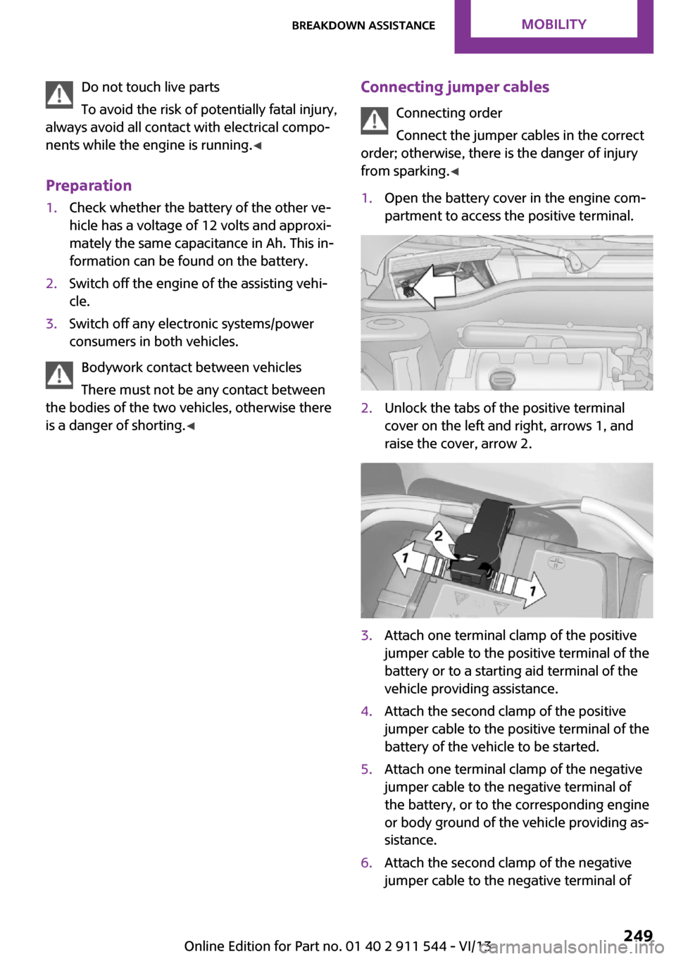
from sparking. ◀1.Open the battery cover in the engine com‐
partment to access the positive terminal.2.Unlock the tabs of the positive terminal
cover on the left and right, arrows 1, and
raise the cover, arrow 2.3.Attach one terminal clamp of the positive
jumper cable to the positive terminal of the
battery or to a starting aid terminal of the
vehicle providing assistance.4.Attach the second clamp of the positive
jumper cable to the positive terminal of the
battery of the vehicle to be started.5.Attach one terminal clamp of the negative
jumper cable to the negative terminal of
the battery, or to the corresponding engine
or body ground of the vehicle providing as‐
sistance.6.Attach the second clamp of the negative
jumper cable to the negative terminal ofSeite 249Breakdown assistanceMobility249
Online Edition for Part no. 01 40 2 911 544 - VI/13
Page 251 of 282
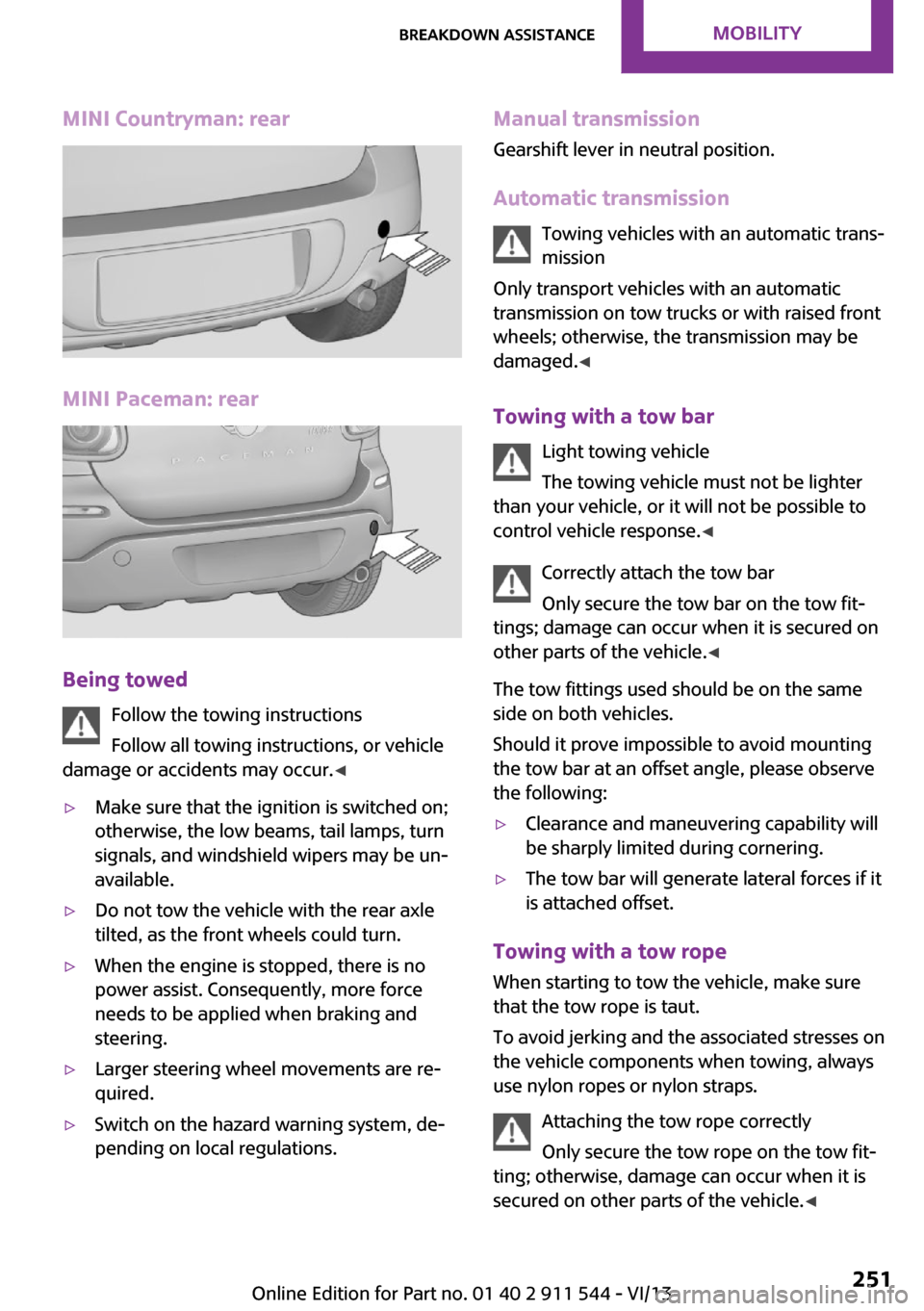
MINI Countryman: rear
MINI Paceman: rear
Being towedFollow the towing instructions
Follow all towing instructions, or vehicle
damage or accidents may occur. ◀
▷Make sure that the ignition is switched on;
otherwise, the low beams, tail lamps, turn
signals, and windshield wipers may be un‐
available.▷Do not tow the vehicle with the rear axle
tilted, as the front wheels could turn.▷When the engine is stopped, there is no
power assist. Consequently, more force
needs to be applied when braking and
steering.▷Larger steering wheel movements are re‐
quired.▷Switch on the hazard warning system, de‐
pending on local regulations.Manual transmission
Gearshift lever in neutral position.
Automatic transmission Towing vehicles with an automatic trans‐
mission
Only transport vehicles with an automatic
transmission on tow trucks or with raised front
wheels; otherwise, the transmission may be
damaged. ◀
Towing with a tow bar Light towing vehicle
The towing vehicle must not be lighter
than your vehicle, or it will not be possible to
control vehicle response. ◀
Correctly attach the tow bar
Only secure the tow bar on the tow fit‐
tings; damage can occur when it is secured on
other parts of the vehicle. ◀
The tow fittings used should be on the same
side on both vehicles.
Should it prove impossible to avoid mounting
the tow bar at an offset angle, please observe
the following:▷Clearance and maneuvering capability will
be sharply limited during cornering.▷The tow bar will generate lateral forces if it
is attached offset.
Towing with a tow rope
When starting to tow the vehicle, make sure
that the tow rope is taut.
To avoid jerking and the associated stresses on
the vehicle components when towing, always
use nylon ropes or nylon straps.
Attaching the tow rope correctly
Only secure the tow rope on the tow fit‐
ting; otherwise, damage can occur when it is
secured on other parts of the vehicle. ◀
Seite 251Breakdown assistanceMobility251
Online Edition for Part no. 01 40 2 911 544 - VI/13
Page 256 of 282

Vehicle paint
Regular care contributes to vehicle value reten‐
tion and protects the paintwork against the
long-term effects of paint-damaging substan‐
ces.
Environmental influences in areas with higher
air pollution or natural contaminants, such as
tree resin or pollen, can have an impact on the
vehicle paint. Therefore, it is important to tailor
the frequency and extent of your car care to
these influences.
Immediately remove especially aggressive sub‐
stances, such as spilled fuel, oil, grease, or bird
droppings, to prevent damage to the paint‐
work.
Correcting paint damage
Depending on the severity of the damage, re‐
pair stone impact damage or scratches imme‐
diately to prevent rust formation.
The manufacturer recommends having paint
damage corrected with a professional repair
paint job according to factory specifications us‐
ing original MINI paint materials.
Preservation
Preservation is needed when water no longer
beads off of the clean paint surfaces. Only use
paint preservation products that contain car‐
nauba or synthetic waxes.
Leather care The leather processed by the manufacturer is a
high quality natural product. Light graininess is
a typical feature of natural leather.
Particles of dust and road grime chafe in pores
and folds, and lead to increased wear and pre‐
mature degradation of the leather surface.
Therefore, remove dust from the leather regu‐
larly, using a cloth or vacuum cleaner.
Make especially sure that light-colored leather
is cleaned regularly as it is more susceptible to
soiling.Twice a year, treat the leather with a leather lo‐
tion as dirt and grease will attack the protective
layer of the leather.
Upholstery material care
Vacuum regularly with a vacuum cleaner to re‐
move superficial soiling.
In case of heavy soiling, e.g., beverage stains,
use a soft sponge or lint-free microfiber cloth in
combination with a suitable interior cleaner.
Follow the instructions on the container.
Clean the upholstery material down to the
seams using large sweeping motions. Avoid
rubbing the material vigorously.
Damage from Velcro® fasteners
Open Velcro® fasteners on pants or other
articles of clothing can damage the seat covers.
Ensure that any Velcro® fasteners are closed. ◀
Caring for special components Interior plastic parts These include:▷Imitation leather surfaces▷Lamp lenses▷Indicator covers▷Matte components
Clean with water and a solvent-free plastic
cleaner if necessary.
Do not use cleansers that contain alcohol
or solvents
Do not use cleansers that contain alcohol or
solvents, such as lacquer thinners, heavy-duty
grease removers, fuel, or such; this could lead
to surface damage. ◀
Rubber seals Only treat with water or a rubber care product.
When cleaning rubber seals, do not use silicone
sprays or other care products containing sili‐
cone; otherwise, noise and damage may result.
Seite 256MobilityCare256
Online Edition for Part no. 01 40 2 911 544 - VI/13
Page 272 of 282
Consumption, refer to Aver‐age fuel consumption 70
Contacts 187, 203
Control Display 20
Control Display, care 257
Control Display, settings 73
Controls and displays 14
Control systems, driving stabil‐ ity 93
Convenient operation– Windows 34
Coolant temperature 69
Cooling function, switching on and off 103
Cooling, maximum 102
Cornering Brake Control, CBC 93
Corrosion on brake discs 124
Cradle for telephone or mobile phone, refer to Snap-in
adapter 200
Cruise control 96
Cupholders 108
Current fuel consumption 70
Current location, storing 138
Curve lights, refer to Adaptive Light Control 80
Cylinders, number of, refer to Engine data 260
D
Dashboard lighting, refer to Instrument lighting 80
Dashboard, refer to Cock‐ pit 14
Dashboard, refer to Dis‐ plays 16
Data, technical 260
Date
– Date format 73– Setting 73
Daytime running lights 79
Decorative trim, care 257
Defogging windows 100
Defroster
– Rear window 100, 103Defrosting windows 100
Defrost setting, refer to De‐ frosting windows 100
Destination entry via the ad‐ dress book 138
Destination guidance with in‐ termediate destinations 143
Destination input, naviga‐ tion 136
Digital compass 106
Digital radio 159
Dip stick, engine oil 234
Directional indicators, refer to Turn signals 61
Displacement, refer to Engine data 260
Display lighting, refer to In‐ strument lighting 80
Displays 16
Displays and controls 14
Displays, care 257
Displays, cleaning 257
Displays, refer to Instrument cluster 16
Disposal– Remote control battery 41
Distance warning, refer to
Park Distance Control
PDC 97
Door key, refer to Remote control with integrated
key 32
Door lock 35
Door lock, confirmation sig‐ nals 35
Doors, manual operation 36
Doors, unlocking and locking
– Confirmation signals 35– From the inside 36– From the outside 34
DOT Quality Grades 224
Drive-off assistant, refer to Hill drive-off assistant 95
Driving notes, breaking in 122
Driving off on hills, refer to Hill drive-off assistant 95
Driving on poor roads 125
Driving stability control sys‐ tems 93
Driving tips, refer to Driving notes 122
Dry air, refer to Cooling func‐ tion 103
DSC Dynamic Stability Con‐ trol 93
DTC Dynamic Traction Con‐ trol 94
DTMF suffix dialing 185, 197
Dynamic destination guid‐ ance 152
Dynamic Stability Control DSC 93
Dynamic Traction Control DTC 94
E Electrical malfunction– Door lock 36– Fuel filler flap 216
Electronic brake-force distri‐
bution 93
Electronic Stability Program ESP, refer to Dynamic Stabil‐
ity Control DSC 93
Emergency activation
– Automatic transmission, re‐
fer to Overriding selector
lever lock 67
Emergency operation, fuel
filler flap, unlocking man‐
ually 216
Emergency operation, refer to
Manual operation
– Door lock 36
Energy, saving, refer to Saving
fuel 130
Engine, breaking in 122
Engine compartment 232
Engine oil, adding 234
Engine oil, additives, refer to Approved engine oils 235
Seite 272ReferenceEverything from A to Z272
Online Edition for Part no. 01 40 2 911 544 - VI/13