light MINI Paceman 2014 (Mini Connected) Manual Online
[x] Cancel search | Manufacturer: MINI, Model Year: 2014, Model line: Paceman, Model: MINI Paceman 2014Pages: 282, PDF Size: 6.76 MB
Page 230 of 282
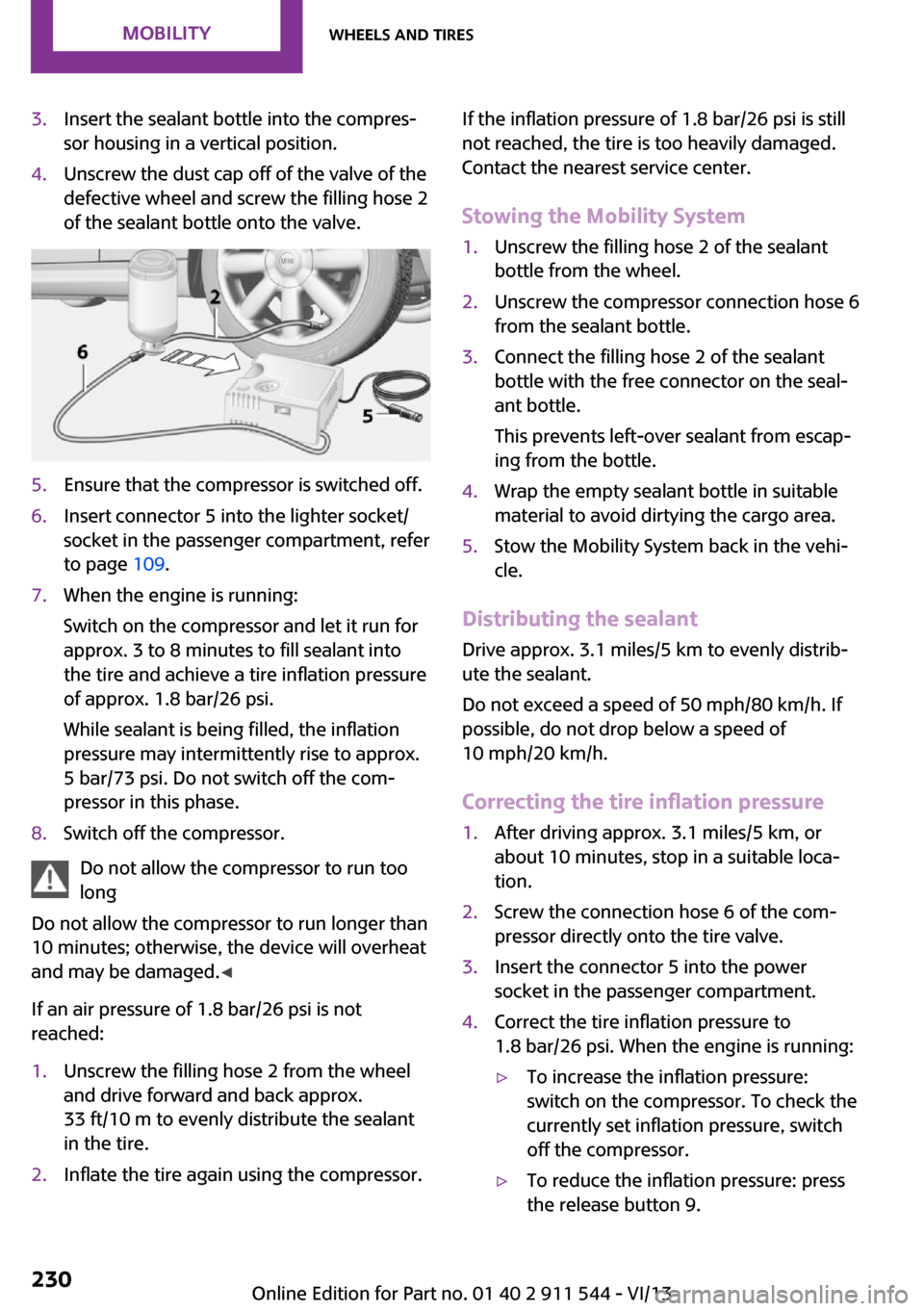
3.Insert the sealant bottle into the compres‐
sor housing in a vertical position.4.Unscrew the dust cap off of the valve of the
defective wheel and screw the filling hose 2
of the sealant bottle onto the valve.5.Ensure that the compressor is switched off.6.Insert connector 5 into the lighter socket/
socket in the passenger compartment, refer
to page 109.7.When the engine is running:
Switch on the compressor and let it run for
approx. 3 to 8 minutes to fill sealant into
the tire and achieve a tire inflation pressure
of approx. 1.8 bar/26 psi.
While sealant is being filled, the inflation
pressure may intermittently rise to approx.
5 bar/73 psi. Do not switch off the com‐
pressor in this phase.8.Switch off the compressor.
Do not allow the compressor to run too
long
Do not allow the compressor to run longer than
10 minutes; otherwise, the device will overheat
and may be damaged. ◀
If an air pressure of 1.8 bar/26 psi is not
reached:
1.Unscrew the filling hose 2 from the wheel
and drive forward and back approx.
33 ft/10 m to evenly distribute the sealant
in the tire.2.Inflate the tire again using the compressor.If the inflation pressure of 1.8 bar/26 psi is still
not reached, the tire is too heavily damaged.
Contact the nearest service center.
Stowing the Mobility System1.Unscrew the filling hose 2 of the sealant
bottle from the wheel.2.Unscrew the compressor connection hose 6
from the sealant bottle.3.Connect the filling hose 2 of the sealant
bottle with the free connector on the seal‐
ant bottle.
This prevents left-over sealant from escap‐
ing from the bottle.4.Wrap the empty sealant bottle in suitable
material to avoid dirtying the cargo area.5.Stow the Mobility System back in the vehi‐
cle.
Distributing the sealant
Drive approx. 3.1 miles/5 km to evenly distrib‐
ute the sealant.
Do not exceed a speed of 50 mph/80 km/h. If
possible, do not drop below a speed of
10 mph/20 km/h.
Correcting the tire inflation pressure
1.After driving approx. 3.1 miles/5 km, or
about 10 minutes, stop in a suitable loca‐
tion.2.Screw the connection hose 6 of the com‐
pressor directly onto the tire valve.3.Insert the connector 5 into the power
socket in the passenger compartment.4.Correct the tire inflation pressure to
1.8 bar/26 psi. When the engine is running:▷To increase the inflation pressure:
switch on the compressor. To check the
currently set inflation pressure, switch
off the compressor.▷To reduce the inflation pressure: press
the release button 9.Seite 230MobilityWheels and tires230
Online Edition for Part no. 01 40 2 911 544 - VI/13
Page 236 of 282
CoolantVehicle equipment
This chapter describes all series equipment as
well as country-specific and special equipment
offered for this model series.Therefore, it also
describes equipment that may not be found in
your vehicle, for instance due to the selected
special equipment or the country version. This
also applies to safety-related functions and sys‐
tems.
General information Danger of burns from hot engine
Do not open the cooling system while the
engine is hot; otherwise, escaping coolant may
cause burns. ◀
Suitable additives
Only use suitable additives; otherwise,
engine damage may occur. The additives are
harmful to your health. ◀
Coolant consists of water and additives.
Not all commercially available additives are
suitable for your MINI vehicle. Ask your service
center for suitable additives.
Coolant temperature
If the coolant and therefore the engine over‐
heat, a warning lamp lights up. A message ap‐
pears on the Control Display.
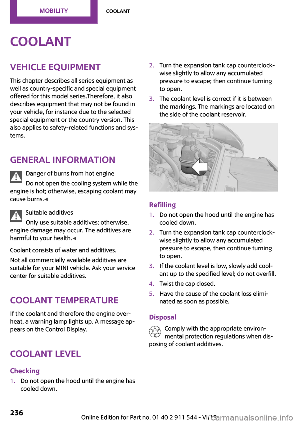
Coolant level Checking1.Do not open the hood until the engine has
cooled down.2.Turn the expansion tank cap counterclock‐
wise slightly to allow any accumulated
pressure to escape; then continue turning
to open.3.The coolant level is correct if it is between
the markings. The markings are located on
the side of the coolant reservoir.
Refilling
1.Do not open the hood until the engine has
cooled down.2.Turn the expansion tank cap counterclock‐
wise slightly to allow any accumulated
pressure to escape, then continue turning
to open.3.If the coolant level is low, slowly add cool‐
ant up to the specified level; do not overfill.4.Twist the cap closed.5.Have the cause of the coolant loss elimi‐
nated as soon as possible.
Disposal
Comply with the appropriate environ‐mental protection regulations when dis‐
posing of coolant additives.
Seite 236MobilityCoolant236
Online Edition for Part no. 01 40 2 911 544 - VI/13
Page 238 of 282

Socket for OBD Onboard
Diagnosis
Socket for Onboard Diagnosis
The socket for Onboard Diagnosis may
only be used by the service center, by work‐
shops that operate according to the specifica‐
tions of the vehicle manufacturer with appro‐
priately trained personnel, and by other
authorized persons. Otherwise, its use may
lead to vehicle malfunctions. ◀
Primary components in the vehicle emissions
can be checked via the OBD socket using a de‐
vice.
Emissions The warning lamps light up. The vehicle
is producing higher emissions. You can
continue your journey, but moderate
your speed and exercise due caution. Have the
vehicle checked as soon as possible.
Under certain circumstances, one of the lamps
flashes or lights up continuously. This indicates
that there is excessive misfiring or a malfunc‐
tion in the engine. If this happens, reduce the
vehicle speed and drive to the next service cen‐
ter promptly. Serious engine misfiring within a
brief period can seriously damage emission
control components, in particular the catalytic
converter. In addition, the mechanical engine
components may become damaged.
If the fuel filler cap is not properly tight‐
ened, the OBD system may conclude
that fuel vapor is escaping; this will cause a dis‐
play to light up. If the filler cap is then tight‐
ened, the display should go out in a few days.Seite 238MobilityMaintenance238
Online Edition for Part no. 01 40 2 911 544 - VI/13
Page 240 of 282
Lamp and bulb replace‐
ment
Notes
Lamps and bulbs Lamps and bulbs make an essential contribu‐
tion to vehicle safety. Therefore, exercise cau‐
tion when handling lamps and bulbs.
The manufacturer of the vehicle recommends
that you entrust corresponding procedures to
the service center if you are unfamiliar with
them or they are not described here.
You can obtain a selection of replacement
bulbs at the service center.
Danger of burns
Only change bulbs when they are cool;
otherwise, there is the danger of getting
burned. ◀
Working on the lighting system
When working on the lighting system,
you should always switch off the lights affected
to prevent short circuits.
To avoid possible injury or equipment damage
when replacing bulbs, observe any instructions
provided by the bulb manufacturer. ◀
Do not touch the bulbs
Do not touch the glass of new bulbs with
your bare hands, as even minute amounts of
contamination will burn into the bulb's surface
and reduce its service life.
Use a clean tissue, cloth or something similar,
or hold the bulb by its base. ◀
Caring for the headlamps, refer to page 255.
For bulb replacement that is not described
here, please contact the service center or a
workshop that works according to the repair
procedures of the manufacturer with corre‐
spondingly trained personnel.For checking and adjusting headlamp aim,
please contact your MINI dealer.
Light-emitting diodes LEDs Light-emitting diodes installed behind translu‐
cent lenses serve as the light source for many
of the controls and displays in the vehicle.
These light-emitting diodes, which operate us‐
ing a concept similar to that applied in conven‐
tional lasers, are officially designated as Class 1
light-emitting diodes.
Do not remove the covers
Do not remove the covers, and never
stare into the unfiltered light for several hours;
otherwise, irritation of the retina could result. ◀
Headlamp glass
Condensation can form on the inside of the
headlamps in cool or humid weather. When the
light is switched on, the condensation evapo‐ rates after a short time. The headlamps do notneed to be changed.
If the condensation in the headlamps does not
evaporate after trips with the lights switched
on, and the amount of moisture in the head‐
lamps increases, for example if water droplets
form, have them checked by your service cen‐
ter.
Bi-xenon headlamps These bulbs have a very long life and the likeli‐
hood of failure is very low, provided that they
are not switched on and off excessively. If a
bulb should nevertheless fail, you can continue
driving cautiously with the front fog lamps, pro‐
vided this is permitted by local laws.
Do not perform work/bulb replacement
on xenon headlamps
Have any work on the xenon lighting system,
including bulb replacement, performed only by
a service center.Seite 240MobilityReplacing components240
Online Edition for Part no. 01 40 2 911 544 - VI/13
Page 246 of 282

Vehicle batteryMaintenance
The battery is maintenance-free, i.e., the elec‐
trolyte will last for the life of the battery in tem‐
perate climate conditions.
The service center will be happy to answer any
questions on the battery.
Battery replacement Use approved vehicle batteries
Only use vehicle batteries that have been
approved for your vehicle by the manufacturer;
otherwise, the vehicle could be damaged and
systems or functions may not be fully availa‐
ble. ◀
Have the vehicle battery registered by the serv‐
ice center after it is replaced to ensure that all
comfort functions are available without restric‐
tions and that any associated Check Control
messages are no longer displayed.
Charging the battery
Note Do not connect the charger to the socket
Do not connect the battery charger to the
socket installed in the vehicle at the factory as
this could damage the battery. ◀
Only charge the battery in the vehicle when the engine is switched off. Connections, refer to
page 248.
General information Ensure that the battery is sufficiently charged to
achieve the full battery life.
It may be necessary to charge the battery in
the following cases:▷When the vehicle is frequently used to
travel short distances.▷When the vehicle has not been driven for
more than one month.Power failure
After a temporary power failure, some equip‐
ment will be restricted in its use and will need
to be reinitialized. In addition, certain individual
settings will be lost and must be updated:▷Time and date: the values must be up‐
dated, refer to page 72.▷Radio: the stations need to be stored again,
refer to page 159.▷Onboard monitor: full functionality will be
restored after some time.▷Glass sunroof, electrical: it may only be pos‐
sible to tilt the roof. The system needs to be
initialized. Contact the service center.
Indicator/warning lamps
Lights up red: the vehicle battery is no
longer being charged. Alternator mal‐
function.
Switch off all unnecessary electrical consumers.
Have the battery checked immediately.
Lights up yellow: the battery charge
level is very low, the battery is old, or it
is not securely connected.
Charge the battery by taking a long drive or us‐
ing an external charger. If the indicators appear
again, have the battery checked as soon as
possible.
Disposing of old batteries Have used batteries disposed of by the
service center after they are replaced or
take them to a recycling center.
Maintain the battery in an upright position for
transport and storage. Secure the battery so
that it does not tip over during transport.
Seite 246MobilityReplacing components246
Online Edition for Part no. 01 40 2 911 544 - VI/13
Page 250 of 282
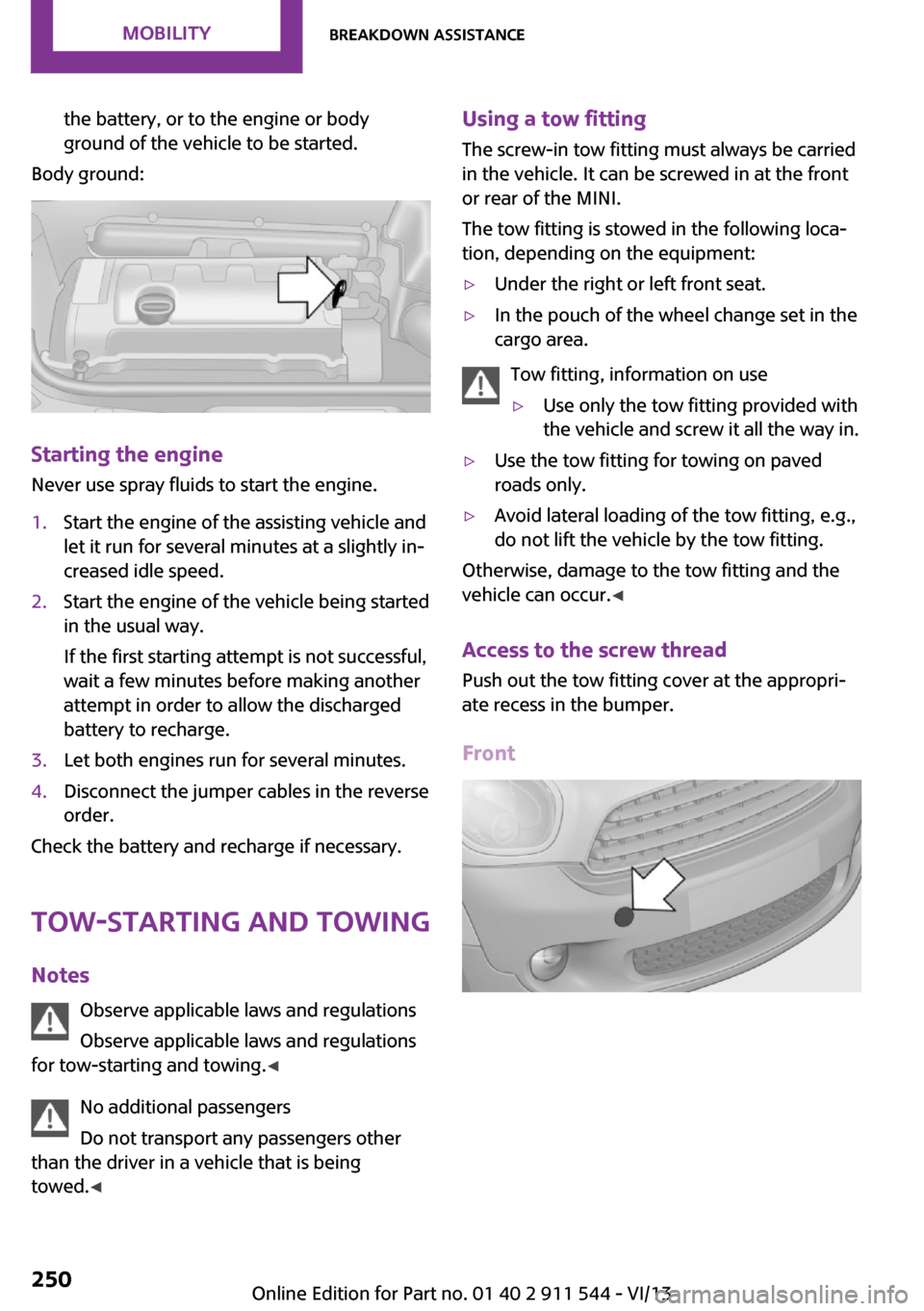
the battery, or to the engine or body
ground of the vehicle to be started.
Body ground:
Starting the engine
Never use spray fluids to start the engine.
1.Start the engine of the assisting vehicle and
let it run for several minutes at a slightly in‐
creased idle speed.2.Start the engine of the vehicle being started
in the usual way.
If the first starting attempt is not successful,
wait a few minutes before making another
attempt in order to allow the discharged
battery to recharge.3.Let both engines run for several minutes.4.Disconnect the jumper cables in the reverse
order.
Check the battery and recharge if necessary.
Tow-starting and towing
Notes Observe applicable laws and regulations
Observe applicable laws and regulations
for tow-starting and towing. ◀
No additional passengers
Do not transport any passengers other
than the driver in a vehicle that is being
towed. ◀
Using a tow fitting
The screw-in tow fitting must always be carried
in the vehicle. It can be screwed in at the front
or rear of the MINI.
The tow fitting is stowed in the following loca‐
tion, depending on the equipment:▷Under the right or left front seat.▷In the pouch of the wheel change set in the
cargo area.
Tow fitting, information on use
▷Use only the tow fitting provided with
the vehicle and screw it all the way in.▷Use the tow fitting for towing on paved
roads only.▷Avoid lateral loading of the tow fitting, e.g.,
do not lift the vehicle by the tow fitting.
Otherwise, damage to the tow fitting and the
vehicle can occur. ◀
Access to the screw thread Push out the tow fitting cover at the appropri‐
ate recess in the bumper.
Front
Seite 250MobilityBreakdown assistance250
Online Edition for Part no. 01 40 2 911 544 - VI/13
Page 251 of 282
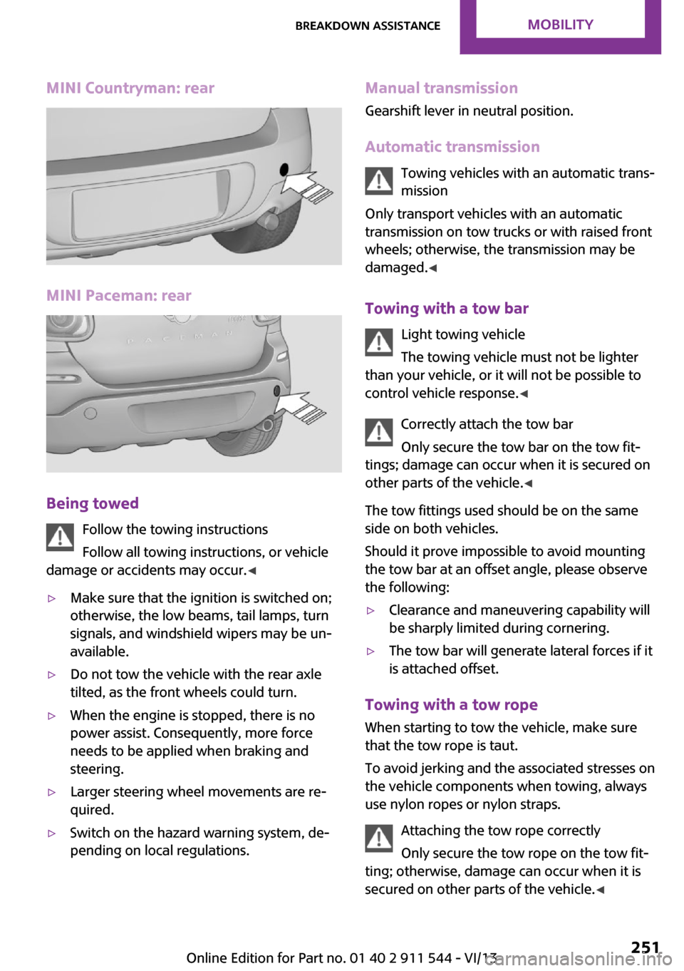
MINI Countryman: rear
MINI Paceman: rear
Being towedFollow the towing instructions
Follow all towing instructions, or vehicle
damage or accidents may occur. ◀
▷Make sure that the ignition is switched on;
otherwise, the low beams, tail lamps, turn
signals, and windshield wipers may be un‐
available.▷Do not tow the vehicle with the rear axle
tilted, as the front wheels could turn.▷When the engine is stopped, there is no
power assist. Consequently, more force
needs to be applied when braking and
steering.▷Larger steering wheel movements are re‐
quired.▷Switch on the hazard warning system, de‐
pending on local regulations.Manual transmission
Gearshift lever in neutral position.
Automatic transmission Towing vehicles with an automatic trans‐
mission
Only transport vehicles with an automatic
transmission on tow trucks or with raised front
wheels; otherwise, the transmission may be
damaged. ◀
Towing with a tow bar Light towing vehicle
The towing vehicle must not be lighter
than your vehicle, or it will not be possible to
control vehicle response. ◀
Correctly attach the tow bar
Only secure the tow bar on the tow fit‐
tings; damage can occur when it is secured on
other parts of the vehicle. ◀
The tow fittings used should be on the same
side on both vehicles.
Should it prove impossible to avoid mounting
the tow bar at an offset angle, please observe
the following:▷Clearance and maneuvering capability will
be sharply limited during cornering.▷The tow bar will generate lateral forces if it
is attached offset.
Towing with a tow rope
When starting to tow the vehicle, make sure
that the tow rope is taut.
To avoid jerking and the associated stresses on
the vehicle components when towing, always
use nylon ropes or nylon straps.
Attaching the tow rope correctly
Only secure the tow rope on the tow fit‐
ting; otherwise, damage can occur when it is
secured on other parts of the vehicle. ◀
Seite 251Breakdown assistanceMobility251
Online Edition for Part no. 01 40 2 911 544 - VI/13
Page 256 of 282

Vehicle paint
Regular care contributes to vehicle value reten‐
tion and protects the paintwork against the
long-term effects of paint-damaging substan‐
ces.
Environmental influences in areas with higher
air pollution or natural contaminants, such as
tree resin or pollen, can have an impact on the
vehicle paint. Therefore, it is important to tailor
the frequency and extent of your car care to
these influences.
Immediately remove especially aggressive sub‐
stances, such as spilled fuel, oil, grease, or bird
droppings, to prevent damage to the paint‐
work.
Correcting paint damage
Depending on the severity of the damage, re‐
pair stone impact damage or scratches imme‐
diately to prevent rust formation.
The manufacturer recommends having paint
damage corrected with a professional repair
paint job according to factory specifications us‐
ing original MINI paint materials.
Preservation
Preservation is needed when water no longer
beads off of the clean paint surfaces. Only use
paint preservation products that contain car‐
nauba or synthetic waxes.
Leather care The leather processed by the manufacturer is a
high quality natural product. Light graininess is
a typical feature of natural leather.
Particles of dust and road grime chafe in pores
and folds, and lead to increased wear and pre‐
mature degradation of the leather surface.
Therefore, remove dust from the leather regu‐
larly, using a cloth or vacuum cleaner.
Make especially sure that light-colored leather
is cleaned regularly as it is more susceptible to
soiling.Twice a year, treat the leather with a leather lo‐
tion as dirt and grease will attack the protective
layer of the leather.
Upholstery material care
Vacuum regularly with a vacuum cleaner to re‐
move superficial soiling.
In case of heavy soiling, e.g., beverage stains,
use a soft sponge or lint-free microfiber cloth in
combination with a suitable interior cleaner.
Follow the instructions on the container.
Clean the upholstery material down to the
seams using large sweeping motions. Avoid
rubbing the material vigorously.
Damage from Velcro® fasteners
Open Velcro® fasteners on pants or other
articles of clothing can damage the seat covers.
Ensure that any Velcro® fasteners are closed. ◀
Caring for special components Interior plastic parts These include:▷Imitation leather surfaces▷Lamp lenses▷Indicator covers▷Matte components
Clean with water and a solvent-free plastic
cleaner if necessary.
Do not use cleansers that contain alcohol
or solvents
Do not use cleansers that contain alcohol or
solvents, such as lacquer thinners, heavy-duty
grease removers, fuel, or such; this could lead
to surface damage. ◀
Rubber seals Only treat with water or a rubber care product.
When cleaning rubber seals, do not use silicone
sprays or other care products containing sili‐
cone; otherwise, noise and damage may result.
Seite 256MobilityCare256
Online Edition for Part no. 01 40 2 911 544 - VI/13
Page 257 of 282

Chrome surfacesCarefully clean components such as the radia‐
tor grille or door handles with an ample supply
of water, possibly with shampoo added, partic‐
ularly when they have been exposed to road
salt. For additional treatment, use a chrome
polish.
Light-alloy wheels
When cleaning the wheels on the vehicle, only
use a neutral wheel rim cleaner with a pH value
of 5 to 9.
Do not use abrasive cleaners or a steam jet hot‐
ter than 140 ℉/60 ℃; otherwise, damage may
result. Adhere to the manufacturer instructions.
Aggressive, acidic, or alkaline cleaners may de‐
stroy the protective coating of neighboring
components such as the brake disc.
Exterior sensors The sensors on the outside of the vehicle, such
as for Park Distance Control, must be kept clean
and free of ice to ensure that they remain fully
functional.
Decorative trim Clean decorative trims and fine wood compo‐
nents with a moist cloth only. Then dry with a
soft cloth.
Safety belts Dirty belt straps impede the reeling action and
thus have a negative impact on safety.
No chemical cleaning
Do not clean chemically; this can destroy
the webbing. ◀
Carpets/floor mats No objects in the area around the pedals
Keep floor mats, carpets, and any other
objects out of the area of motion of the pedals;
otherwise, the function of the pedals could be
impeded while drivingDo not place additional floor mats over existing
mats or other objects.
Only use floor mats that have been approved
for the vehicle and can be properly fixed in
place.
Ensure that the floor mats are securely fastened
again when they are returned after being re‐
moved, such as for cleaning. ◀
Floor mats can be removed for cleaning.
If they are very dirty, clean with a microfiber
cloth and water or an interior cleaner. To pre‐
vent matting of the carpet, rub back and forth
in the direction of travel only.
Displays
To clean the displays, such as the radio or dis‐
play elements, use an antistatic microfiber
cloth.
Cleaning displays
Do not use chemical or household cleans‐
ers.
Keep all fluids and moisture away from the
unit.
Otherwise, they could affect or damage surfa‐
ces or electrical components.
Avoid pressing too hard when cleaning and do
not use abrasive materials; otherwise, damage
can result. ◀
CD/DVD drives No cleaning CD
Do not use cleaning CDs; otherwise, parts
of the drive may become damaged. ◀
Long-term vehicle storage
Your service center can advise you on what to
consider when storing the vehicle for longer
than three months.Seite 257CareMobility257
Online Edition for Part no. 01 40 2 911 544 - VI/13
Page 264 of 282
Short commands for voice
activation systemVehicle equipment
This chapter describes all series equipment as
well as country-specific and special equipment
offered for this model series.Therefore, it also
describes equipment that may not be found in
your vehicle, for instance due to the selected
special equipment or the country version. This
also applies to safety-related functions and sys‐
tems.
General information Instructions for voice activation system, refer to
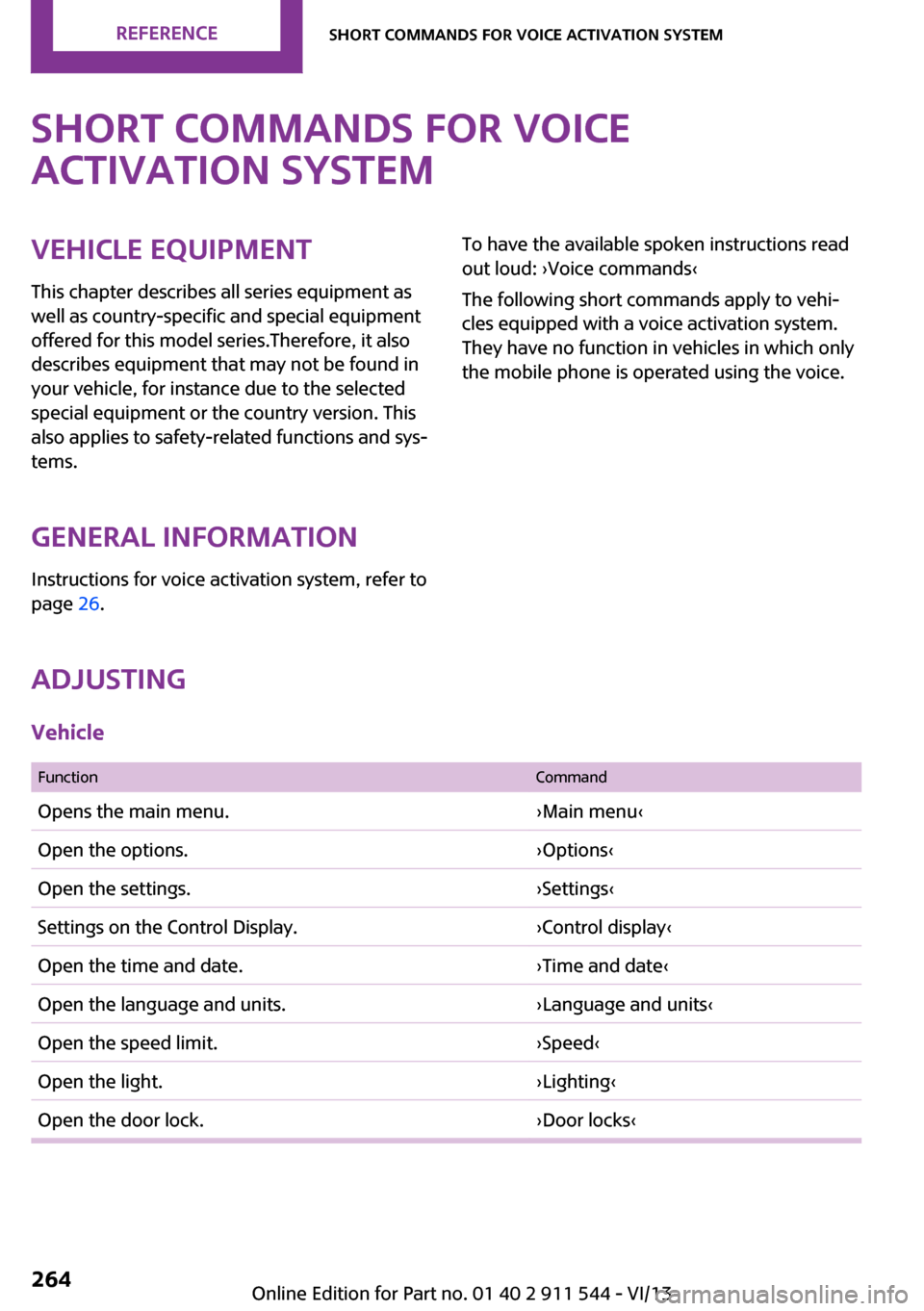
page 26.To have the available spoken instructions read
out loud: ›Voice commands‹
The following short commands apply to vehi‐
cles equipped with a voice activation system.
They have no function in vehicles in which only
the mobile phone is operated using the voice.
Adjusting
Vehicle
FunctionCommandOpens the main menu.›Main menu‹Open the options.›Options‹Open the settings.›Settings‹Settings on the Control Display.›Control display‹Open the time and date.›Time and date‹Open the language and units.›Language and units‹Open the speed limit.›Speed‹Open the light.›Lighting‹Open the door lock.›Door locks‹Seite 264ReferenceShort commands for voice activation system264
Online Edition for Part no. 01 40 2 911 544 - VI/13