air condition MINI Paceman 2014 Owner's Manual (Mini Connected)
[x] Cancel search | Manufacturer: MINI, Model Year: 2014, Model line: Paceman, Model: MINI Paceman 2014Pages: 282, PDF Size: 6.76 MB
Page 7 of 282
For your own safety
Warranty Your vehicle is technically configured for the
operating conditions and registration require‐
ments applying in the country of first delivery
— homologation. If your vehicle is to be oper‐
ated in a different country it might be neces‐
sary to adapt your vehicle to potentially differ‐
ing operating conditions and permit
requirements. If your vehicle does not comply
with the homologation requirements in a cer‐
tain country you cannot lodge warranty claims
for your vehicle there. Further information can
be obtained from your Service Centre.
Maintenance and repairs Advanced technology, e.g., the use of modern
materials and high-performance electronics,
requires suitable maintenance and repair
methods.
Therefore, have this work performed only by a
MINI service center or a workshop that works
according to MINI repair procedures with ap‐
propriately trained personnel.
If this work is not carried out properly, there is
the danger of subsequent damage and related
safety hazards.
Parts and accessories
For your own safety, use genuine parts and ac‐
cessories approved by the manufacturer of the
MINI. When you purchase accessories tested
and approved by the manufacturer of the MINI
and Original MINI Parts, you simultaneously ac‐
quire the assurance that they have been thor‐
oughly tested by the manufacturer of the MINI
to ensure optimum performance when instal‐
led on your vehicle. The manufacturer of the
MINI warrants these parts to be free from de‐
fects in material and workmanship. The manu‐
facturer of the MINI will not accept any liability
for damage resulting from installation of parts
and accessories not approved by the manufac‐turer of the MINI. The manufacturer of the MINI
cannot test every product made by other man‐
ufacturers to verify if it can be used on a MINI
safely and without risk to either the vehicle, its
operation, or its occupants. Original MINI Parts,
MINI Accessories and other products approved
by the manufacturer of the MINI, together with
professional advice on using these items, are
available from all MINI Dealers. Installation and
operation of non-MINI approved accessories
such as alarms, radios, amplifiers, radar detec‐
tors, wheels, suspension components, brake
dust shields, telephones, including operation of
any mobile phone from within the vehicle with‐
out using an externally mounted antenna, or
transceiver equipment, for instance, CBs,
walkie-talkies, ham radios or similar accesso‐
ries, may cause extensive damage to the vehi‐
cle, compromise its safety, interfere with the
vehicle's electrical system or affect the validity
of the MINI Limited Warranty. See your MINI
Dealer for additional information. Maintenance,
replacement, or repair of the emission control
devices and systems may be performed by any
automotive repair establishment or individual
using any certified automotive part.
California Proposition 65 Warning
California laws require us to state the following
warning:
Engine exhaust and a wide variety of automo‐
bile components and parts, including compo‐
nents found in the interior furnishings in a vehi‐
cle, contain or emit chemicals known to the
State of California to cause cancer and birth de‐
fects and reproductive harm. In addition, cer‐
tain fluids contained in vehicles and certain
products of component wear contain or emit
chemicals known to the State of California to
cause cancer and birth defects or other repro‐
ductive harm. Battery posts, terminals and re‐
lated accessories contain lead and lead com‐
pounds. Wash your hands after handling. Used
engine oil contains chemicals that have caused
cancer in laboratory animals. Always protectSeite 7Notes7
Online Edition for Part no. 01 40 2 911 544 - VI/13
Page 8 of 282
your skin by washing thoroughly with soap and
water.
Service and warranty
We recommend that you read this publication
thoroughly. Your vehicle is covered by the fol‐
lowing warranties:▷New Vehicle Limited Warranty.▷Rust Perforation Limited Warranty.▷Federal Emissions System Defect Warranty.▷Federal Emissions Performance Warranty.▷California Emission Control System Limited
Warranty.
Detailed information about these warranties is
listed in the Service and Warranty Information
Booklet for US models or in the Warranty and
Service Guide Booklet for Canadian models.
Your vehicle has been specifically adapted and
designed to meet the particular operating con‐
ditions and homologation requirements in your
country and continental region in order to de‐
liver the full driving pleasure while the vehicle is
operated under those conditions. If you wish to
operate your vehicle in another country or re‐
gion, you may be required to adapt your vehi‐
cle to meet different prevailing operating con‐
ditions and homologation requirements. You
should also be aware of any applicable war‐
ranty limitations or exclusions for such country
or region. In such case, please contact Cus‐
tomer Relations for further information.
Maintenance
Maintain the vehicle regularly to sustain the
road safety, operational reliability and the New
Vehicle Limited Warranty.
Specifications for required maintenance meas‐
ures:
▷MINI Maintenance system▷Service and Warranty Information Booklet
for US models▷Warranty and Service Guide Booklet for
Canadian modelsIf the vehicle is not maintained according to
these specifications, this could result in serious
damage to the vehicle. Such damage is not
covered by the MINI New Vehicle Limited War‐
ranty.
Data memory
Numerous electronic components in your vehi‐
cle contain data memories that store technical
information on the vehicle condition, events and faults, either temporarily or permanently.This technical information generally documents
the state of a component, a module, a system
or the environment.▷Operating conditions of system compo‐
nents, such as filling levels.▷Status messages from the vehicle and its in‐
dividual components, such as wheel rpm/
speed, motion delay, transverse accelera‐
tion.▷Malfunctions and defects in important sys‐
tem components, such as lights and brakes.▷Vehicle responses to special driving situa‐
tions, such as airbag deployment, use of
the stability control systems.▷Ambient conditions, such as the tempera‐
ture.
These data are of a technical nature only and
are used to detect and eliminate faults and to
optimize vehicle functions. Travel profiles of
routes driven with the vehicle cannot be cre‐
ated from these data. If services are used, for
instance in the event of repairs, service proc‐
esses, warranty cases, quality assurance, etc.,
this technical information can be read out from
the event and fault data memories by service
personnel, including the manufacturer, using
special diagnosis tools. This service personnel
can provide you with more information if
needed. After troubleshooting, the information
in the fault memory is cleared or overwritten
continuously.
Seite 8Notes8
Online Edition for Part no. 01 40 2 911 544 - VI/13
Page 18 of 282
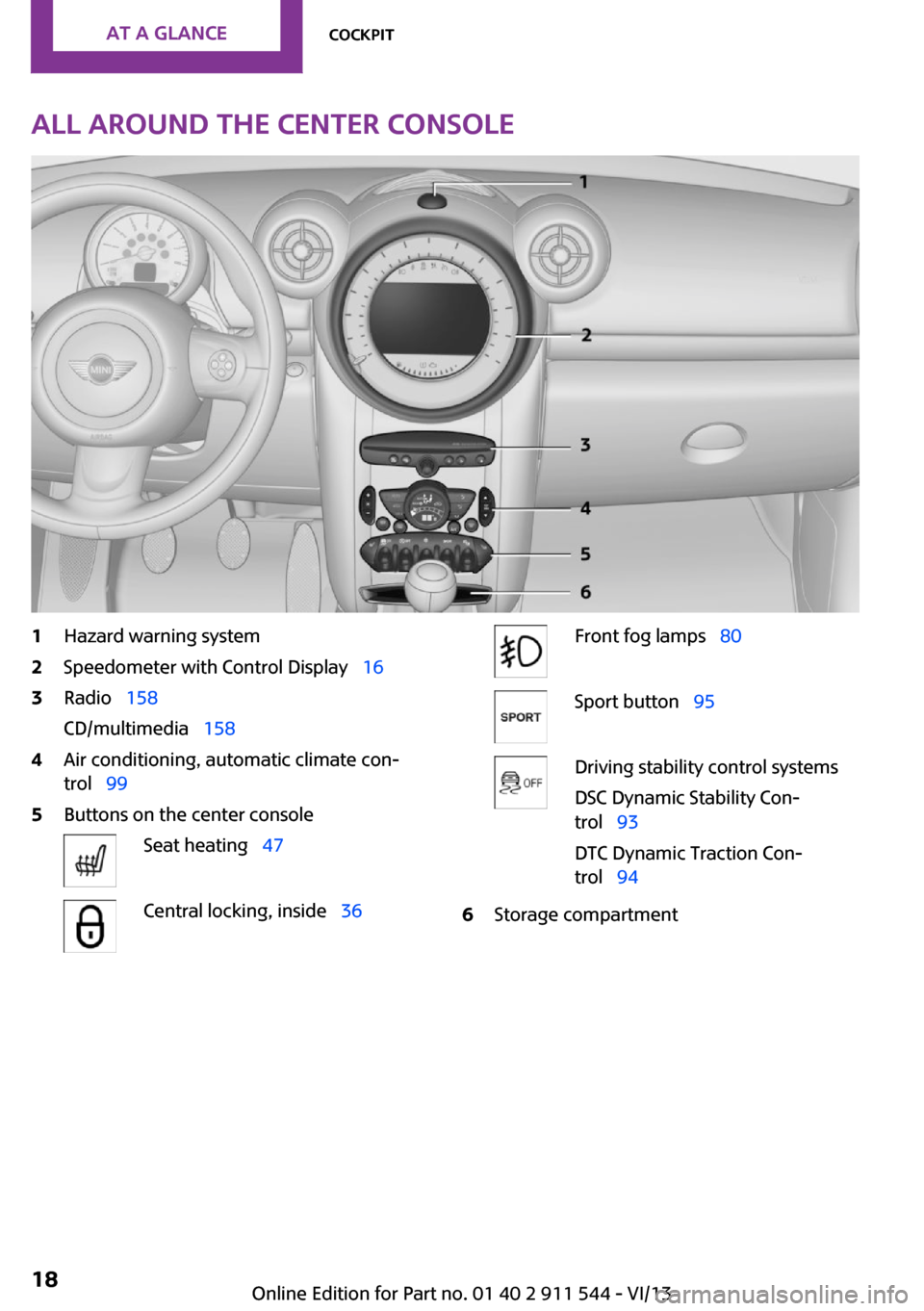
All around the center console1Hazard warning system2Speedometer with Control Display 163Radio 158
CD/multimedia 1584Air conditioning, automatic climate con‐
trol 995Buttons on the center consoleSeat heating 47Central locking, inside 36Front fog lamps 80Sport button 95Driving stability control systems
DSC Dynamic Stability Con‐
trol 93
DTC Dynamic Traction Con‐
trol 946Storage compartmentSeite 18At a glanceCockpit18
Online Edition for Part no. 01 40 2 911 544 - VI/13
Page 35 of 282
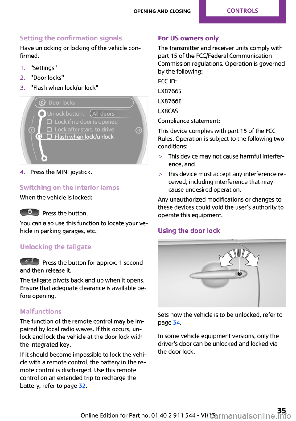
Setting the confirmation signalsHave unlocking or locking of the vehicle con‐
firmed.1."Settings"2."Door locks"3."Flash when lock/unlock"4.Press the MINI joystick.
Switching on the interior lamps
When the vehicle is locked:
Press the button.
You can also use this function to locate your ve‐
hicle in parking garages, etc.
Unlocking the tailgate
Press the button for approx. 1 second
and then release it.
The tailgate pivots back and up when it opens.
Ensure that adequate clearance is available be‐
fore opening.
Malfunctions The function of the remote control may be im‐
paired by local radio waves. If this occurs, un‐
lock and lock the vehicle at the door lock with
the integrated key.
If it should become impossible to lock the vehi‐
cle with a remote control, the battery in the re‐
mote control is discharged. Use this remote
control on an extended trip to recharge the
battery, refer to page 32.
For US owners only
The transmitter and receiver units comply with
part 15 of the FCC/Federal Communication
Commission regulations. Operation is governed by the following:
FCC ID:
LX8766S
LX8766E
LX8CAS
Compliance statement:
This device complies with part 15 of the FCC
Rules. Operation is subject to the following two
conditions:▷This device may not cause harmful interfer‐
ence, and▷this device must accept any interference re‐
ceived, including interference that may
cause undesired operation.
Any unauthorized modifications or changes to
these devices could void the user's authority to
operate this equipment.
Using the door lock
Sets how the vehicle is to be unlocked, refer to
page 34.
In some vehicle equipment versions, only the
driver's door can be unlocked and locked via
the door lock.
Seite 35Opening and closingControls35
Online Edition for Part no. 01 40 2 911 544 - VI/13
Page 89 of 282
completed automatically as you drive. On the
Control Display, the tires are shown in green
and "Status: TPM active" is displayed again.
The trip can be interrupted at any time. If you
drive away again, the process resumes auto‐
matically.
If a flat tire is detected while the system is re‐
setting, all tires on the Control Display are dis‐
played in yellow. The message "Low tire!" is
shown.
Low tire pressure message The warning lamps come on in yellow
and red. A message is displayed on the
onboard monitor. In addition, a signal
sounds.▷There is a flat tire or substantial loss of infla‐
tion pressure on the indicated wheel.▷The system was not reset after a wheel
change and thus issues warnings based on
the inflation pressures initialized last.1.Reduce your speed and stop cautiously.
Avoid sudden braking and steering maneu‐
vers.2.Check whether the vehicle is fitted with
regular tires or run-flat tires.
Run-flat tires, refer to page 228, are la‐
beled with a circular symbol containing the
letters RSC marked on the tire sidewall.
Do not continue driving without run-flat
tires
Do not continue driving if the vehicle is not
equipped with run-flat tires; continued driving
may result in serious accidents. ◀
When a low inflation pressure is indicated, DSC
Dynamic Stability Control is switched on if nec‐
essary.
Actions in the event of a flat tire Normal tires
1.Identify the damaged tire.Do this by checking the air pressure in all
four tires. The tire pressure gauge of the
Mobility System, refer to page 229, can be
used for this purpose.
If the tire inflation pressure in all four tires is
correct, the Tire Pressure Monitor may not
have been reset. Reset the system.
If an identification is not possible, please
contact the service center.2.Rectify the flat tire using the Mobility Sys‐
tem, refer to page 229.
Use of tire sealant, e.g., the Mobility Sys‐
tem, may damage the TPM wheel electron‐
ics. In this case, have the electronics
checked at the next opportunity and have
them replaced if necessary.
Run-flat tires
You can continue driving with a damaged tire
at speeds up to 50 mph/80 km/h.
Do not continue driving without run-flat
tires
Do not continue driving if the vehicle is not
equipped with run-flat tires; continued driving
may result in serious accidents. ◀
Continued driving with a flat tire
If continuing to drive with a damaged tire:
1.Avoid sudden braking and steering maneu‐
vers.2.Do not exceed a speed of 50 mph/80 km/h.3.Check the air pressure in all four tires at the
next opportunity.
If the tire inflation pressure in all four tires is
correct, the Tire Pressure Monitor may not
have been reset. Reset the system.
Possible driving distance with complete loss of
tire inflation pressure:
The possible driving distance after a loss of tire
inflation pressure depends on the cargo load
and the driving style and conditions.
Seite 89SafetyControls89
Online Edition for Part no. 01 40 2 911 544 - VI/13
Page 99 of 282

ClimateVehicle equipment
This chapter describes all series equipment as
well as country-specific and special equipment
offered for this model series.Therefore, it alsodescribes equipment that may not be found in
your vehicle, for instance due to the selected
special equipment or the country version. This
also applies to safety-related functions and sys‐
tems.
Air conditioning
1Air volume2Cooling function3Recirculated air mode4Temperature5Rear window defroster6Vent settings7Windshield heatingAir volume
Vary the air volume. The higher
the rate, the more effective the
heating or cooling will be.
The air flow rate may be reduced
or the blower may be switched
off entirely to save on battery power.Switching the system on/off
Turn the rotary switch for the air volume to 0.
The blower and air conditioner are completely switched off and the air supply is cut off.
Set any air volume to switch on the air condi‐
tioning.Seite 99ClimateControls99
Online Edition for Part no. 01 40 2 911 544 - VI/13
Page 115 of 282

Opening
Turn the switch in the direction of the arrow.ClosingMove the switch to the vertical position by
turning it in the opposite direction of the arrow.
Depending on the temperature setting of the
air conditioning or automatic climate control,
high temperatures may occur in the glove com‐
partment.
USB interface for data transfer Updating the navigation data, refer to
page 134, from the USB medium via the USB
interface in the glove compartment.
Observe the following when connecting:
▷Do not use force when plugging the con‐
nector into the USB interface.▷Do not connect devices such as fans or
lamps to the USB interface.▷Do not connect USB hard drives.▷Do not use the USB interface to recharge
external devices.
Center armrest
The center armrest between the front seats
contains a storage compartment or a cover for
the snap-in adapter, refer to page 200, de‐
pending on the equipment.
The center armrest between the rear seats con‐
tains a storage compartment.
Do not position tall accessory parts directly on
the center rail of the center armrest; otherwise,
they may be damaged when the center arm‐
rest is opened or closed.
Center armrest front
Opening
Press the button, arrow, and pull up the lid.
MINI Paceman: center armrest, rear
Removing
The rear center armrest can be removed to en‐
large the loading area.
1.Turn the handwheel counterclockwise all
the way to open it, arrow 1.2.Push the center armrest back slightly in the
base plate, arrow 2.3.Lift the center armrest at the front and
pivot it out.Seite 115Storage compartmentsControls115
Online Edition for Part no. 01 40 2 911 544 - VI/13
Page 130 of 282
Saving fuelVehicle equipment
This chapter describes all series equipment as
well as country-specific and special equipment
offered for this model series.Therefore, it also
describes equipment that may not be found in
your vehicle, for instance due to the selected
special equipment or the country version. This
also applies to safety-related functions and sys‐
tems.
General information Your vehicle contains advanced technology for
the reduction of fuel consumption and emis‐
sions.
Fuel consumption depends on a number of dif‐
ferent factors. The implementation of certain
measures, driving style and regular mainte‐ nance can have an influence on fuel consump‐
tion and on the environmental impact.
Remove unnecessary cargo Additional weight increases fuel consumption.
Remove attached parts following use Remove unneeded auxiliary mirrors, roof or
rear luggage racks after use.
Attached parts on the vehicle impair the aero‐
dynamics and increase the fuel consumption.
Close both windows Open windows causes higher air resistance and
thus increases fuel consumption.
Check the tire inflation pressure
regularly
Check and, if necessary, correct the tire infla‐
tion pressure, refer to page 220, at least twice
a month and before starting on a long trip.Low tire inflation pressure increases rolling re‐
sistance and thus raises fuel consumption and
tire wear.
Drive away without delayDo not wait for the engine to warm-up while
the vehicle remains stationary. Start driving
right away, but at moderate engine speeds.
This is the fastest way for the cold engine to
reach its operating temperature.
Look well ahead when driving Avoid unnecessary acceleration and braking. To
achieve this, maintain a suitable distance to the
vehicle driving ahead of you.
Driving smoothly and looking ahead reduces
fuel consumption.
Avoid high engine speeds Use 1st gear to get the vehicle in motion. Be‐
ginning with 2nd gear, accelerate rapidly. When
accelerating, shift up before reaching high en‐
gine speeds.
When you reach the desired speed, shift into
the highest applicable gear and drive with the
engine speed as low as possible and at a con‐
stant speed.
As a rule: driving at low engine speeds lowers
fuel consumption and reduces wear.
Use coasting conditions
When approaching a red light, take your foot
off the accelerator and coast to a halt in the
highest applicable gear.
On a downhill slope, take your foot off the ac‐
celerator and coast in a suitable gear.
The flow of fuel is interrupted while coasting.Seite 130Driving tipsSaving fuel130
Online Edition for Part no. 01 40 2 911 544 - VI/13
Page 180 of 282
Bluetooth hands-free systemVehicle equipmentThis chapter describes all series equipment as
well as country-specific and special equipment
offered for this model series.Therefore, it also
describes equipment that may not be found in
your vehicle, for instance due to the selected
special equipment or the country version. This
also applies to safety-related functions and sys‐
tems.
At a glance The concept
Mobile phones can be connected with the vehi‐
cle via Bluetooth.
Bluetooth® is a registered trademark of Blue‐
tooth® SIG, Inc.
After these devices are paired once, they are
recognized automatically when the ignition is
switched on as soon as they are in the vehicle
and can then be operated via the onboard
monitor, the buttons on the steering wheel,
and voice activation.
Up to four external devices can be paired.
Certain functions may need to be enabled by
the mobile phone provider or service provider.
Using the mobile phone while driving
Make entries only when traffic and road
conditions allow. Do not hold the mobile phone
in your hand while you are driving; use the
hands-free system instead. If you do not ob‐
serve this precaution, you can endanger the ve‐
hicle occupants and other road users. ◀
Approved mobile phones
Details on which mobile phones are supported
by the hands-free system can be obtained at
www.mini.com/connectivity.Displaying the vehicle identification
number and software part number
The vehicle identification number and software
part number are needed to determine which
mobile phones are supported by the mobile
phone preparation package. The software ver‐
sion of the mobile phone may also be required.1."Telephone"2.Open "Options".3."Bluetooth® info"4."Display system information"
These approved mobile phones with a certain
software version, support the vehicle functions
described below.
Malfunctions may occur with other mobile
phones or software versions.
Do not operate a mobile phone that is con‐
nected to the vehicle on the mobile phone key‐
pad, as this may lead to a malfunction.
Notes
At high temperatures, the charging function of
the mobile phone may be limited and functions
may not be executed.
When using the mobile phone via the vehicle,
note the operating instructions of the mobile phone.
Pairing/unpairing the
mobile phone
Requirements
▷The mobile phone is suitable, refer to
page 180.▷The mobile phone is ready for operation.▷Bluetooth is activated in the vehicle and on
the mobile phone.Seite 180CommunicationBluetooth hands-free system180
Online Edition for Part no. 01 40 2 911 544 - VI/13
Page 183 of 282
▷A multi-character passkey may be needed.▷Did it take longer than 30 seconds to enter
the passkey? Repeat the pairing procedure.▷Are too many Bluetooth devices connected
to the mobile phone or vehicle? Delete con‐
nections with other devices if necessary.▷The mobile phone is in power-save mode
or has only a limited remaining battery life.
Charge the mobile phone via the charging
cable.▷Depending on the mobile phone, it is possi‐
ble that only one mobile phone can be con‐
nected to the vehicle. Unpair the connected
mobile phone from the vehicle and pair
and connect only one mobile phone.
The mobile phone no longer reacts.
▷Switch the mobile phone off and on again.▷Is the ambient temperature too high or
low? Do not expose the mobile phone to
extreme environmental conditions.
No phone book entries or only some phone
book entries are displayed, or they are incom‐
plete.
▷Transmission of the phone book entries is
not yet complete.▷It is possible that only the phone book en‐
tries of the mobile phone or the SIM card
are transmitted.▷It may not be possible to display phone
book entries with special characters.▷The number of phone book entries to be
stored is too high.▷Is the data volume of the contact too large,
e. g., due to stored information such as
notes? Reduce the data volume of the con‐
tact.
The phone connection quality is poor.
▷The strength of the Bluetooth signal on the
mobile phone can be adjusted, depending
on the mobile phone.▷Place the mobile phone in the area of the
center console.If all points in this list have been checked and
the required function is still not available, con‐
tact Customer Relations or the service center.
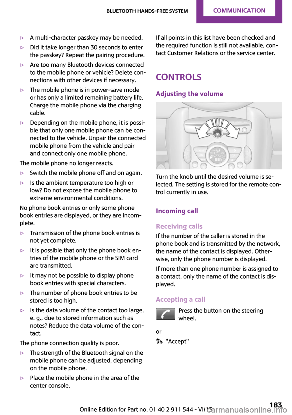
Controls Adjusting the volume
Turn the knob until the desired volume is se‐
lected. The setting is stored for the remote con‐
trol currently in use.
Incoming call
Receiving calls If the number of the caller is stored in the
phone book and is transmitted by the network,
the name of the contact is displayed. Other‐
wise, only the phone number is displayed.
If more than one phone number is assigned to
a contact, only the name of the contact is dis‐
played.
Accepting a call Press the button on the steering
wheel.
or
"Accept"
Seite 183Bluetooth hands-free systemCommunication183
Online Edition for Part no. 01 40 2 911 544 - VI/13