key battery MINI Paceman 2014 Owner's Manual (Mini Connected)
[x] Cancel search | Manufacturer: MINI, Model Year: 2014, Model line: Paceman, Model: MINI Paceman 2014Pages: 282, PDF Size: 6.76 MB
Page 32 of 282
Opening and closingVehicle equipmentThis chapter describes all series equipment as
well as country-specific and special equipment
offered for this model series.Therefore, it also
describes equipment that may not be found in
your vehicle, for instance due to the selected
special equipment or the country version. This
also applies to safety-related functions and sys‐
tems.
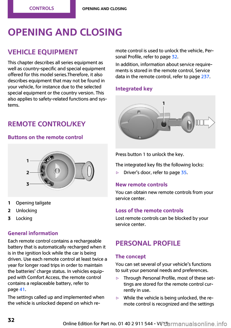
Remote control/key Buttons on the remote control1Opening tailgate2Unlocking3Locking
General information
Each remote control contains a rechargeable
battery that is automatically recharged when it
is in the ignition lock while the car is being
driven. Use each remote control at least twice a
year for longer road trips in order to maintain
the batteries' charge status. In vehicles equip‐
ped with Comfort Access, the remote control
contains a replaceable battery, refer to
page 41.
The settings called up and implemented when
the vehicle is unlocked depend on which re‐
mote control is used to unlock the vehicle, Per‐
sonal Profile, refer to page 32.
In addition, information about service require‐
ments is stored in the remote control, Service
data in the remote control, refer to page 237.
Integrated key
Press button 1 to unlock the key.
The integrated key fits the following locks:
▷Driver's door, refer to page 35.
New remote controls
You can obtain new remote controls from your
service center.
Loss of the remote controls Lost remote controls can be blocked by your
service center.
Personal Profile
The concept
You can set several of your vehicle's functions
to suit your personal needs and preferences.
▷Through Personal Profile, most of these set‐
tings are stored for the remote control cur‐
rently in use.▷While the vehicle is being unlocked, the re‐
mote control is recognized and the settingsSeite 32ControlsOpening and closing32
Online Edition for Part no. 01 40 2 911 544 - VI/13
Page 35 of 282
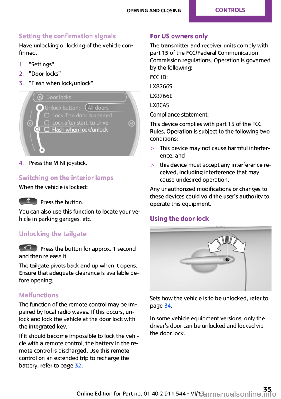
Setting the confirmation signalsHave unlocking or locking of the vehicle con‐
firmed.1."Settings"2."Door locks"3."Flash when lock/unlock"4.Press the MINI joystick.
Switching on the interior lamps
When the vehicle is locked:
Press the button.
You can also use this function to locate your ve‐
hicle in parking garages, etc.
Unlocking the tailgate
Press the button for approx. 1 second
and then release it.
The tailgate pivots back and up when it opens.
Ensure that adequate clearance is available be‐
fore opening.
Malfunctions The function of the remote control may be im‐
paired by local radio waves. If this occurs, un‐
lock and lock the vehicle at the door lock with
the integrated key.
If it should become impossible to lock the vehi‐
cle with a remote control, the battery in the re‐
mote control is discharged. Use this remote
control on an extended trip to recharge the
battery, refer to page 32.
For US owners only
The transmitter and receiver units comply with
part 15 of the FCC/Federal Communication
Commission regulations. Operation is governed by the following:
FCC ID:
LX8766S
LX8766E
LX8CAS
Compliance statement:
This device complies with part 15 of the FCC
Rules. Operation is subject to the following two
conditions:▷This device may not cause harmful interfer‐
ence, and▷this device must accept any interference re‐
ceived, including interference that may
cause undesired operation.
Any unauthorized modifications or changes to
these devices could void the user's authority to
operate this equipment.
Using the door lock
Sets how the vehicle is to be unlocked, refer to
page 34.
In some vehicle equipment versions, only the
driver's door can be unlocked and locked via
the door lock.
Seite 35Opening and closingControls35
Online Edition for Part no. 01 40 2 911 544 - VI/13
Page 40 of 282
When the door and tailgate are closed again
and the remote control is detected inside the
vehicle, the windows and the sunroof can be
operated again.
Insert the remote control into the ignition lock
to be able to operate the windows and the sun‐
roof while the engine is switched off and the
doors are open.
Switching on the radio ready state Press the Start/Stop button to switch on the
radio ready state, refer to page 58.
Do not depress the brake or the clutch; other‐
wise, the engine will start.
Starting the engine The engine can be started or the ignition can
be switched on, refer to page 58, when a re‐
mote control is inside the vehicle. It is not nec‐
essary to insert a remote control into the igni‐
tion lock.
Switching off the engine in cars with
automatic transmission
The engine can only be switched off with the
selector lever in position P, refer to page 65.
To switch off the engine with the selector lever
in position N, the remote control must be in‐
serted in the ignition lock.
Before driving a vehicle with automatic
transmission into a car wash1.Insert the remote control into the ignition
switch.2.Depress the brake pedal.3.Move the selector lever to position N.4.Switch the engine off.
The vehicle can roll.
Malfunction The Comfort Access functions can be disturbed
by local radio waves, such as by a mobile
phone in the immediate vicinity of the remote
control or when a mobile phone is being
charged in the vehicle.
If this occurs, open or close the vehicle using
the buttons on the remote control or use the
integrated key in the door lock.
To start the engine afterward, insert the remote
control into the ignition switch.
Warning lamps The warning lamp in the instrument
cluster lights up when you attempt to
start the engine: the engine cannot be
started.
The remote control is not in the vehicle or has a
malfunction. Take the remote control with you
inside the vehicle or have it checked. If neces‐
sary, insert another remote control into the ig‐
nition switch.
The warning lamp in the instrument
cluster lights up while the engine is run‐
ning: the remote control is no longer in‐
side the vehicle.
After switching off the engine, the engine can
only be started again within approx. 10 sec‐
onds if no door has been opened.
The indicator lamp lights up and a mes‐
sage appears on the Control Display: re‐
place the remote control battery.Seite 40ControlsOpening and closing40
Online Edition for Part no. 01 40 2 911 544 - VI/13
Page 41 of 282
Replacing the battery
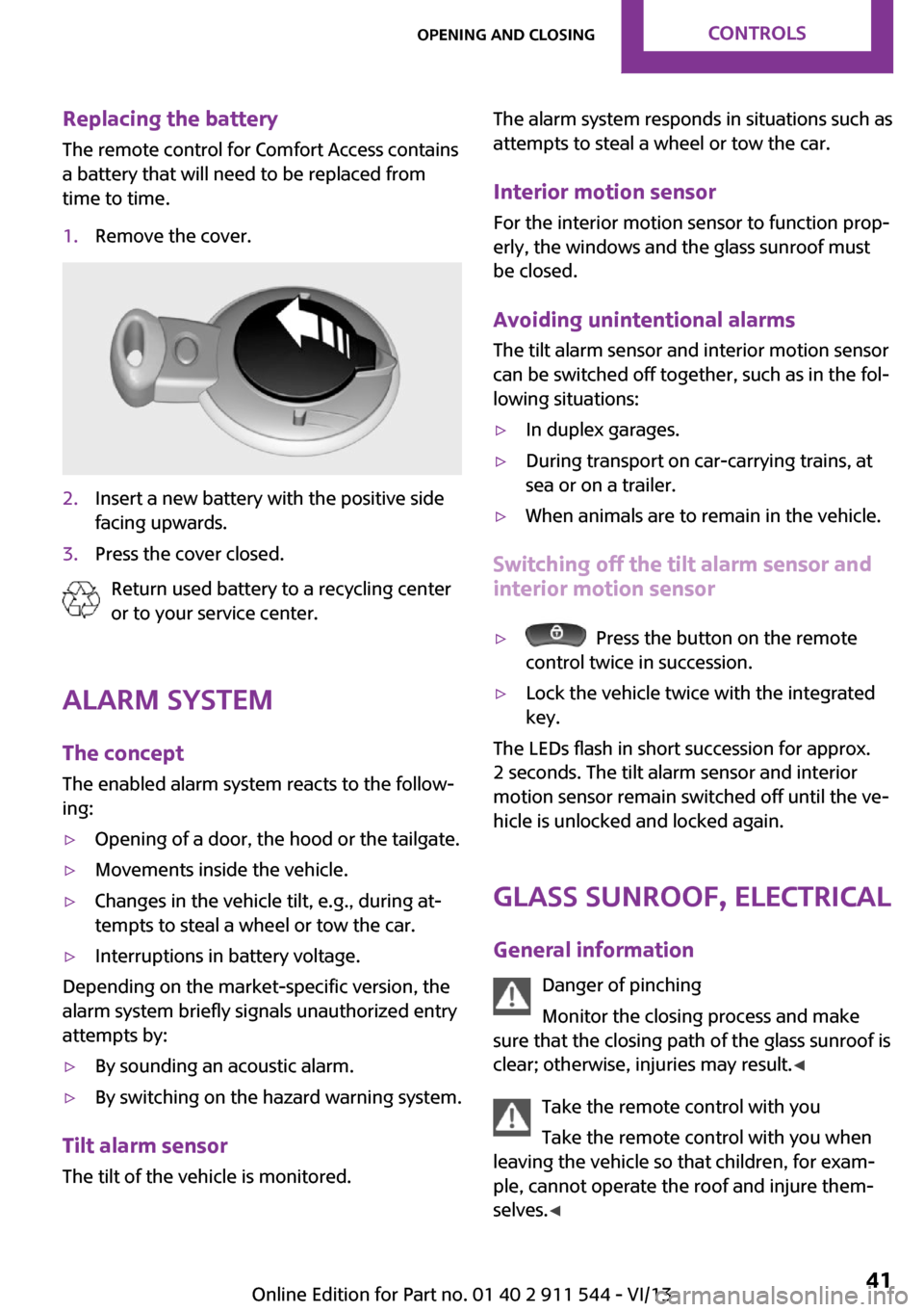
The remote control for Comfort Access contains
a battery that will need to be replaced from
time to time.1.Remove the cover.2.Insert a new battery with the positive side
facing upwards.3.Press the cover closed.
Return used battery to a recycling center
or to your service center.
Alarm system
The concept
The enabled alarm system reacts to the follow‐
ing:
▷Opening of a door, the hood or the tailgate.▷Movements inside the vehicle.▷Changes in the vehicle tilt, e.g., during at‐
tempts to steal a wheel or tow the car.▷Interruptions in battery voltage.
Depending on the market-specific version, the
alarm system briefly signals unauthorized entry
attempts by:
▷By sounding an acoustic alarm.▷By switching on the hazard warning system.
Tilt alarm sensor
The tilt of the vehicle is monitored.
The alarm system responds in situations such as
attempts to steal a wheel or tow the car.
Interior motion sensor For the interior motion sensor to function prop‐
erly, the windows and the glass sunroof must
be closed.
Avoiding unintentional alarms
The tilt alarm sensor and interior motion sensor
can be switched off together, such as in the fol‐
lowing situations:▷In duplex garages.▷During transport on car-carrying trains, at
sea or on a trailer.▷When animals are to remain in the vehicle.
Switching off the tilt alarm sensor and
interior motion sensor
▷ Press the button on the remote
control twice in succession.▷Lock the vehicle twice with the integrated
key.
The LEDs flash in short succession for approx.
2 seconds. The tilt alarm sensor and interior
motion sensor remain switched off until the ve‐
hicle is unlocked and locked again.
Glass sunroof, electrical
General information Danger of pinching
Monitor the closing process and make
sure that the closing path of the glass sunroof is
clear; otherwise, injuries may result. ◀
Take the remote control with you
Take the remote control with you when
leaving the vehicle so that children, for exam‐
ple, cannot operate the roof and injure them‐
selves. ◀
Seite 41Opening and closingControls41
Online Edition for Part no. 01 40 2 911 544 - VI/13
Page 183 of 282
▷A multi-character passkey may be needed.▷Did it take longer than 30 seconds to enter
the passkey? Repeat the pairing procedure.▷Are too many Bluetooth devices connected
to the mobile phone or vehicle? Delete con‐
nections with other devices if necessary.▷The mobile phone is in power-save mode
or has only a limited remaining battery life.
Charge the mobile phone via the charging
cable.▷Depending on the mobile phone, it is possi‐
ble that only one mobile phone can be con‐
nected to the vehicle. Unpair the connected
mobile phone from the vehicle and pair
and connect only one mobile phone.
The mobile phone no longer reacts.
▷Switch the mobile phone off and on again.▷Is the ambient temperature too high or
low? Do not expose the mobile phone to
extreme environmental conditions.
No phone book entries or only some phone
book entries are displayed, or they are incom‐
plete.
▷Transmission of the phone book entries is
not yet complete.▷It is possible that only the phone book en‐
tries of the mobile phone or the SIM card
are transmitted.▷It may not be possible to display phone
book entries with special characters.▷The number of phone book entries to be
stored is too high.▷Is the data volume of the contact too large,
e. g., due to stored information such as
notes? Reduce the data volume of the con‐
tact.
The phone connection quality is poor.
▷The strength of the Bluetooth signal on the
mobile phone can be adjusted, depending
on the mobile phone.▷Place the mobile phone in the area of the
center console.If all points in this list have been checked and
the required function is still not available, con‐
tact Customer Relations or the service center.
Controls Adjusting the volume
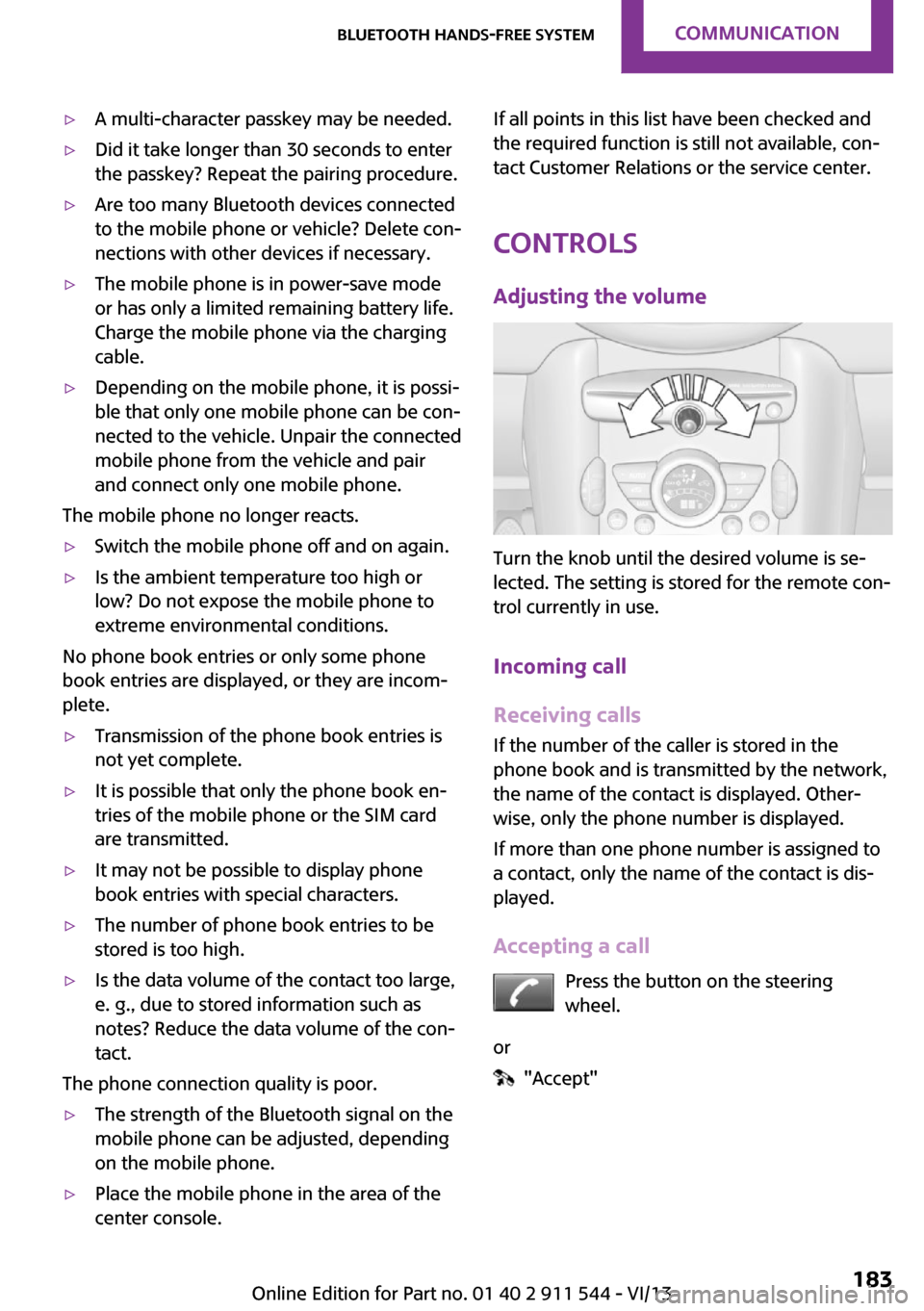
Turn the knob until the desired volume is se‐
lected. The setting is stored for the remote con‐
trol currently in use.
Incoming call
Receiving calls If the number of the caller is stored in the
phone book and is transmitted by the network,
the name of the contact is displayed. Other‐
wise, only the phone number is displayed.
If more than one phone number is assigned to
a contact, only the name of the contact is dis‐
played.
Accepting a call Press the button on the steering
wheel.
or
"Accept"
Seite 183Bluetooth hands-free systemCommunication183
Online Edition for Part no. 01 40 2 911 544 - VI/13
Page 190 of 282
Bluetooth mobile phone
preparation packageVehicle equipment This chapter describes all series equipment as
well as country-specific and special equipment
offered for this model series.Therefore, it also
describes equipment that may not be found in
your vehicle, for instance due to the selected
special equipment or the country version. This
also applies to safety-related functions and sys‐
tems.
At a glance The concept
Mobile phones or other external devices such
as audio players can be connected to the vehi‐
cle via Bluetooth.
Bluetooth® is a registered trademark of Blue‐
tooth® SIG, Inc.
After these devices are paired once, they are
recognized automatically when the ignition is
switched on as soon as they are in the vehicle
and can then be operated via the onboard
monitor, using the buttons on the steering
wheel, and via voice activation.
Depending on their functionality, external devi‐
ces can be used via the vehicle as a telephone
or as an audio source. The telephone functions
are described in the following. Operating the
audio functions, refer to page 173.
Up to four external devices can be paired.
Certain functions may need to be enabled by the mobile phone provider or service provider.
Using the mobile phone while driving
Make entries only when traffic and road
conditions allow. Do not hold the mobile phone
in your hand while you are driving; use thehands-free system instead. If you do not ob‐
serve this precaution, you can endanger the ve‐
hicle occupants and other road users. ◀
Snap-in adapter
The snap-in adapter is used to:▷Hold the mobile phone.▷Recharge the battery.▷Connect the mobile phone to an outside
antenna of the vehicle.
This provides for better network reception
and consistent sound quality.
Approved mobile phones
Displaying the vehicle identification
number and software part number
The vehicle identification number and software
part number are needed to determine which
mobile phones are supported by the mobile
phone preparation package. The software ver‐
sion of the mobile phone may also be required.
1."Telephone"2.Open "Options".3."Bluetooth® info"4."Display system information"
These approved mobile phones with a certain
software version, support the vehicle functions
described below.
Malfunctions may occur with other mobile
phones or software versions.
Do not operate a mobile phone that is con‐
nected to the vehicle on the mobile phone key‐
pad, as this may lead to a malfunction.
Seite 190CommunicationBluetooth mobile phone preparation package190
Online Edition for Part no. 01 40 2 911 544 - VI/13
Page 272 of 282
Consumption, refer to Aver‐age fuel consumption 70
Contacts 187, 203
Control Display 20
Control Display, care 257
Control Display, settings 73
Controls and displays 14
Control systems, driving stabil‐ ity 93
Convenient operation– Windows 34
Coolant temperature 69
Cooling function, switching on and off 103
Cooling, maximum 102
Cornering Brake Control, CBC 93
Corrosion on brake discs 124
Cradle for telephone or mobile phone, refer to Snap-in
adapter 200
Cruise control 96
Cupholders 108
Current fuel consumption 70
Current location, storing 138
Curve lights, refer to Adaptive Light Control 80
Cylinders, number of, refer to Engine data 260
D
Dashboard lighting, refer to Instrument lighting 80
Dashboard, refer to Cock‐ pit 14
Dashboard, refer to Dis‐ plays 16
Data, technical 260
Date
– Date format 73– Setting 73
Daytime running lights 79
Decorative trim, care 257
Defogging windows 100
Defroster
– Rear window 100, 103Defrosting windows 100
Defrost setting, refer to De‐ frosting windows 100
Destination entry via the ad‐ dress book 138
Destination guidance with in‐ termediate destinations 143
Destination input, naviga‐ tion 136
Digital compass 106
Digital radio 159
Dip stick, engine oil 234
Directional indicators, refer to Turn signals 61
Displacement, refer to Engine data 260
Display lighting, refer to In‐ strument lighting 80
Displays 16
Displays and controls 14
Displays, care 257
Displays, cleaning 257
Displays, refer to Instrument cluster 16
Disposal– Remote control battery 41
Distance warning, refer to
Park Distance Control
PDC 97
Door key, refer to Remote control with integrated
key 32
Door lock 35
Door lock, confirmation sig‐ nals 35
Doors, manual operation 36
Doors, unlocking and locking
– Confirmation signals 35– From the inside 36– From the outside 34
DOT Quality Grades 224
Drive-off assistant, refer to Hill drive-off assistant 95
Driving notes, breaking in 122
Driving off on hills, refer to Hill drive-off assistant 95
Driving on poor roads 125
Driving stability control sys‐ tems 93
Driving tips, refer to Driving notes 122
Dry air, refer to Cooling func‐ tion 103
DSC Dynamic Stability Con‐ trol 93
DTC Dynamic Traction Con‐ trol 94
DTMF suffix dialing 185, 197
Dynamic destination guid‐ ance 152
Dynamic Stability Control DSC 93
Dynamic Traction Control DTC 94
E Electrical malfunction– Door lock 36– Fuel filler flap 216
Electronic brake-force distri‐
bution 93
Electronic Stability Program ESP, refer to Dynamic Stabil‐
ity Control DSC 93
Emergency activation
– Automatic transmission, re‐
fer to Overriding selector
lever lock 67
Emergency operation, fuel
filler flap, unlocking man‐
ually 216
Emergency operation, refer to
Manual operation
– Door lock 36
Energy, saving, refer to Saving
fuel 130
Engine, breaking in 122
Engine compartment 232
Engine oil, adding 234
Engine oil, additives, refer to Approved engine oils 235
Seite 272ReferenceEverything from A to Z272
Online Edition for Part no. 01 40 2 911 544 - VI/13