low beam MINI Paceman 2014 Owner's Manual (Mini Connected)
[x] Cancel search | Manufacturer: MINI, Model Year: 2014, Model line: Paceman, Model: MINI Paceman 2014Pages: 282, PDF Size: 6.76 MB
Page 14 of 282
CockpitVehicle equipment
This chapter describes all series equipment as
well as country-specific and special equipment
offered for this model series.Therefore, it alsodescribes equipment that may not be found in
your vehicle, for instance due to the selected
special equipment or the country version. This
also applies to safety-related functions and sys‐
tems.
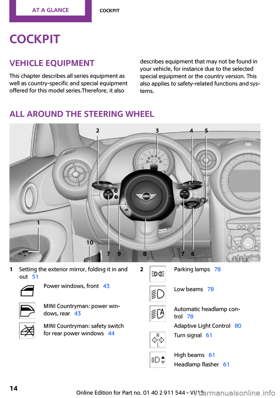
All around the steering wheel
1Setting the exterior mirror, folding it in and
out 51Power windows, front 43MINI Countryman: power win‐
dows, rear 43MINI Countryman: safety switch
for rear power windows 442Parking lamps 78Low beams 78Automatic headlamp con‐
trol 78
Adaptive Light Control 80Turn signal 61High beams 61
Headlamp flasher 61Seite 14At a glanceCockpit14
Online Edition for Part no. 01 40 2 911 544 - VI/13
Page 17 of 282
Indicator/warning lamps
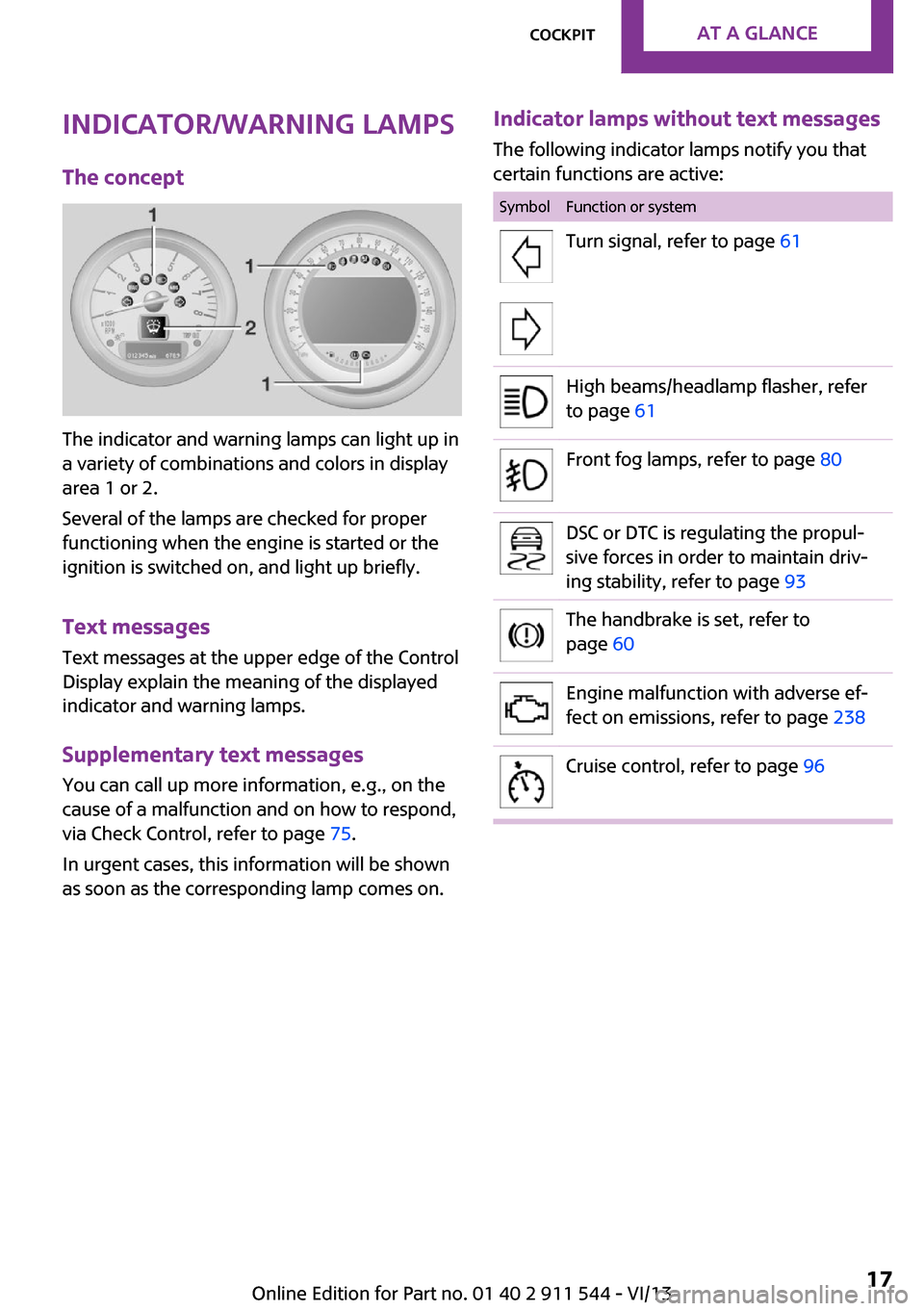
The concept
The indicator and warning lamps can light up in
a variety of combinations and colors in display
area 1 or 2.
Several of the lamps are checked for proper
functioning when the engine is started or the
ignition is switched on, and light up briefly.
Text messages
Text messages at the upper edge of the Control
Display explain the meaning of the displayed
indicator and warning lamps.
Supplementary text messages
You can call up more information, e.g., on the
cause of a malfunction and on how to respond,
via Check Control, refer to page 75.
In urgent cases, this information will be shown
as soon as the corresponding lamp comes on.
Indicator lamps without text messages
The following indicator lamps notify you that
certain functions are active:SymbolFunction or systemTurn signal, refer to page 61High beams/headlamp flasher, refer
to page 61Front fog lamps, refer to page 80DSC or DTC is regulating the propul‐
sive forces in order to maintain driv‐
ing stability, refer to page 93The handbrake is set, refer to
page 60Engine malfunction with adverse ef‐
fect on emissions, refer to page 238Cruise control, refer to page 96Seite 17CockpitAt a glance17
Online Edition for Part no. 01 40 2 911 544 - VI/13
Page 59 of 282
To save battery power when the engine is off,
switch off the ignition and any unnecessary
electronic systems/power consumers.
Radio ready state and ignition off All indicator and warning lamps in the displays
go out.
The ignition switches off automatically when
the driver's door is opened. Pressing the Start/
Stop button again switches the ignition back
on.
For example, the ignition is not switched off in
the following situations:▷Depress the clutch or brake pedal.▷The low beams are switched on
Starting the engine
General information Enclosed areas
Do not let the engine run in enclosed
areas; otherwise, breathing of exhaust fumes
may lead to loss of consciousness and death.
The exhaust gases contain carbon monoxide,
an odorless and colorless but highly toxic gas. ◀
Unattended vehicle
Do not leave the car unattended with the
engine running; otherwise, it presents a poten‐
tial source of danger.
Before leaving the car with the engine running,
shift to neutral or engage transmission posi‐
tion P and set the handbrake firmly; otherwise,
the vehicle may begin to roll. ◀
Frequent starting in quick succession
Avoid repeated futile attempts at starting
the car and avoid starting the car frequently in
quick succession. Otherwise, the fuel is not
burned or is inadequately burned, and there is
the danger of overheating and damaging the
catalytic converter. ◀
Do not wait for the engine to warm-up while
the vehicle remains stationary; start driving
right away, but at moderate engine speeds.
Do not depress the accelerator when starting
the engine.
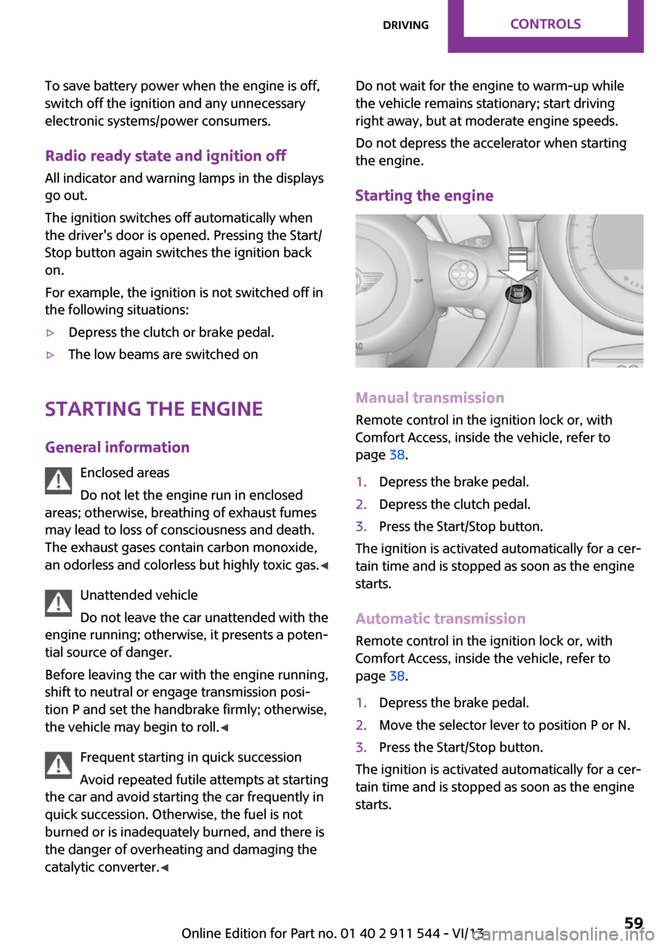
Starting the engine
Manual transmission
Remote control in the ignition lock or, with
Comfort Access, inside the vehicle, refer to
page 38.
1.Depress the brake pedal.2.Depress the clutch pedal.3.Press the Start/Stop button.
The ignition is activated automatically for a cer‐
tain time and is stopped as soon as the engine
starts.
Automatic transmission
Remote control in the ignition lock or, with
Comfort Access, inside the vehicle, refer to
page 38.
1.Depress the brake pedal.2.Move the selector lever to position P or N.3.Press the Start/Stop button.
The ignition is activated automatically for a cer‐
tain time and is stopped as soon as the engine
starts.
Seite 59DrivingControls59
Online Edition for Part no. 01 40 2 911 544 - VI/13
Page 74 of 282
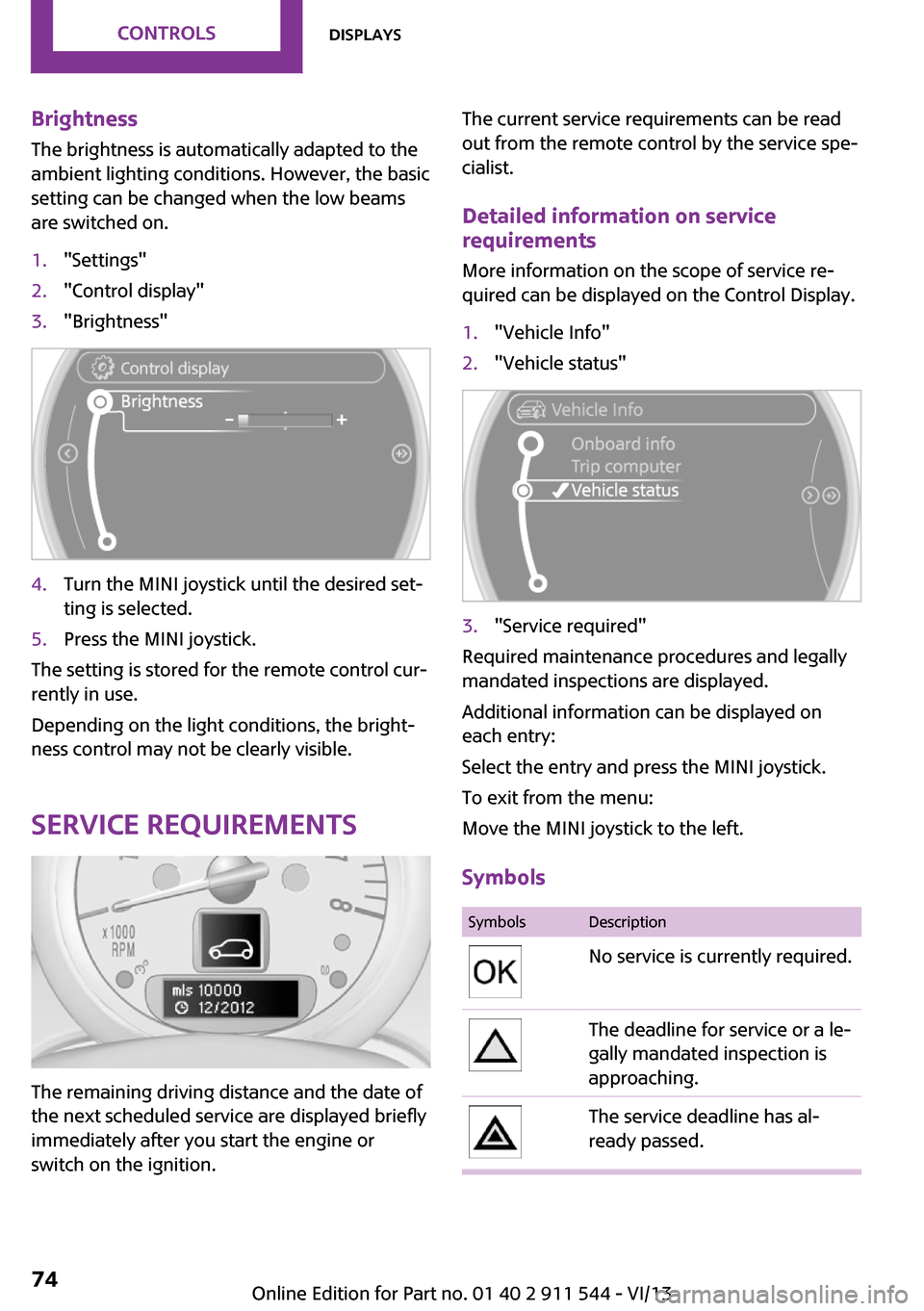
Brightness
The brightness is automatically adapted to the
ambient lighting conditions. However, the basic
setting can be changed when the low beams
are switched on.1."Settings"2."Control display"3."Brightness"4.Turn the MINI joystick until the desired set‐
ting is selected.5.Press the MINI joystick.
The setting is stored for the remote control cur‐
rently in use.
Depending on the light conditions, the bright‐
ness control may not be clearly visible.
Service requirements
The remaining driving distance and the date of
the next scheduled service are displayed briefly
immediately after you start the engine or
switch on the ignition.
The current service requirements can be read
out from the remote control by the service spe‐
cialist.
Detailed information on service
requirements
More information on the scope of service re‐
quired can be displayed on the Control Display.1."Vehicle Info"2."Vehicle status"3."Service required"
Required maintenance procedures and legally
mandated inspections are displayed.
Additional information can be displayed on
each entry:
Select the entry and press the MINI joystick.
To exit from the menu:
Move the MINI joystick to the left.
Symbols
SymbolsDescriptionNo service is currently required.The deadline for service or a le‐
gally mandated inspection is
approaching.The service deadline has al‐
ready passed.Seite 74ControlsDisplays74
Online Edition for Part no. 01 40 2 911 544 - VI/13
Page 78 of 282
LampsVehicle equipmentThis chapter describes all series equipment as
well as country-specific and special equipment
offered for this model series.Therefore, it also
describes equipment that may not be found in
your vehicle, for instance due to the selected
special equipment or the country version. This
also applies to safety-related functions and sys‐
tems.
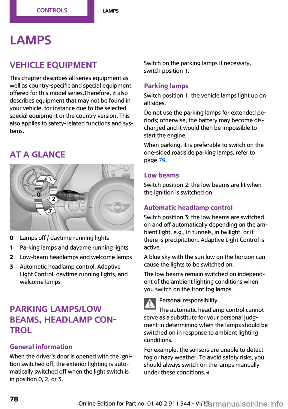
At a glance0Lamps off / daytime running lights1Parking lamps and daytime running lights2Low-beam headlamps and welcome lamps3Automatic headlamp control, Adaptive
Light Control, daytime running lights, and
welcome lamps
Parking lamps/low
beams, headlamp con‐
trol
General information
When the driver's door is opened with the igni‐
tion switched off, the exterior lighting is auto‐
matically switched off when the light switch is
in position 0, 2, or 3.
Switch on the parking lamps if necessary,
switch position 1.
Parking lamps Switch position 1: the vehicle lamps light up on
all sides.
Do not use the parking lamps for extended pe‐
riods; otherwise, the battery may become dis‐
charged and it would then be impossible to
start the engine.
When parking, it is preferable to switch on the
one-sided roadside parking lamps, refer to
page 79.
Low beams Switch position 2: the low beams are lit when
the ignition is switched on.
Automatic headlamp control Switch position 3: the low beams are switched
on and off automatically depending on the am‐
bient light, e.g., in tunnels, in twilight, or if
there is precipitation. Adaptive Light Control is
active.
A blue sky with the sun low on the horizon can
cause the lights to be switched on.
The low beams remain switched on independ‐
ent of the ambient lighting conditions when
you switch on the front fog lamps.
Personal responsibility
The automatic headlamp control cannot
serve as a substitute for your personal judg‐
ment in determining when the lamps should be
switched on in response to ambient lighting
conditions.
For example, the sensors are unable to detect
fog or hazy weather. To avoid safety risks, you
should always switch on the lamps manually
under these conditions. ◀Seite 78ControlsLamps78
Online Edition for Part no. 01 40 2 911 544 - VI/13
Page 79 of 282
When the daytime running lights are activated,
the low beams are always switched on in
switch position 3 when the ignition is switched
on.
The exterior lighting goes out automatically af‐
ter the vehicle is switched off.
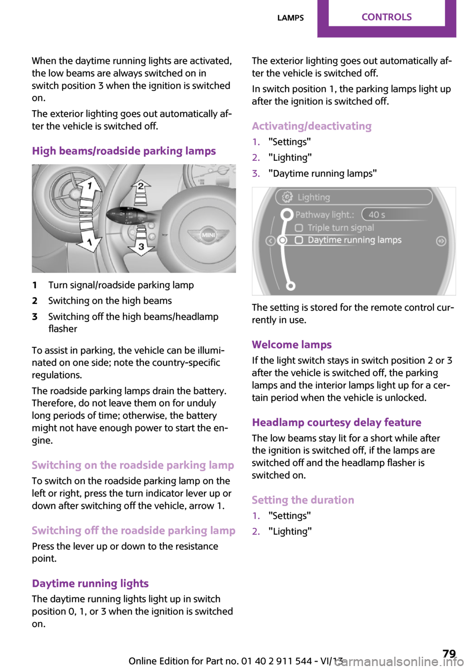
High beams/roadside parking lamps1Turn signal/roadside parking lamp2Switching on the high beams3Switching off the high beams/headlamp
flasher
To assist in parking, the vehicle can be illumi‐
nated on one side; note the country-specific
regulations.
The roadside parking lamps drain the battery.
Therefore, do not leave them on for unduly
long periods of time; otherwise, the battery
might not have enough power to start the en‐
gine.
Switching on the roadside parking lamp
To switch on the roadside parking lamp on the
left or right, press the turn indicator lever up or
down after switching off the vehicle, arrow 1.
Switching off the roadside parking lamp
Press the lever up or down to the resistance
point.
Daytime running lights
The daytime running lights light up in switch
position 0, 1, or 3 when the ignition is switched
on.
The exterior lighting goes out automatically af‐
ter the vehicle is switched off.
In switch position 1, the parking lamps light up
after the ignition is switched off.
Activating/deactivating1."Settings"2."Lighting"3."Daytime running lamps"
The setting is stored for the remote control cur‐
rently in use.
Welcome lamps If the light switch stays in switch position 2 or 3
after the vehicle is switched off, the parking
lamps and the interior lamps light up for a cer‐
tain period when the vehicle is unlocked.
Headlamp courtesy delay feature The low beams stay lit for a short while after
the ignition is switched off, if the lamps are
switched off and the headlamp flasher is
switched on.
Setting the duration
1."Settings"2."Lighting"Seite 79LampsControls79
Online Edition for Part no. 01 40 2 911 544 - VI/13
Page 80 of 282
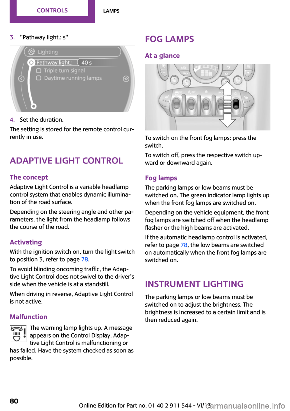
3."Pathway light.: s"4.Set the duration.
The setting is stored for the remote control cur‐
rently in use.
Adaptive Light Control
The concept
Adaptive Light Control is a variable headlamp
control system that enables dynamic illumina‐
tion of the road surface.
Depending on the steering angle and other pa‐
rameters, the light from the headlamp follows
the course of the road.
Activating
With the ignition switch on, turn the light switch
to position 3, refer to page 78.
To avoid blinding oncoming traffic, the Adap‐
tive Light Control does not swivel to the driver's
side when the vehicle is at a standstill.
When driving in reverse, Adaptive Light Control
is not active.
Malfunction The warning lamp lights up. A message
appears on the Control Display. Adap‐
tive Light Control is malfunctioning or
has failed. Have the system checked as soon as
possible.
Fog lamps
At a glance
To switch on the front fog lamps: press the
switch.
To switch off, press the respective switch up‐
ward or downward again.
Fog lamps
The parking lamps or low beams must be
switched on. The green indicator lamp lights up
when the front fog lamps are switched on.
Depending on the vehicle equipment, the front
fog lamps are switched off when the headlamp
flasher or the high beams are activated.
If the automatic headlamp control is activated,
refer to page 78, the low beams are switched
on automatically when the front fog lamps are
switched on.
Instrument lightingThe parking lamps or low beams must be
switched on to adjust the brightness. The
brightness is increased to a certain limit and is
then reduced again.
Seite 80ControlsLamps80
Online Edition for Part no. 01 40 2 911 544 - VI/13
Page 241 of 282
Due to the high voltage present in the system,
there is the danger of fatal injuries if work is
carried out improperly. ◀
Front lamps, bulb replacement
Halogen low beams and high beams
Bulb H13, 60/55 watt
Wear protective goggles and gloves
Halogen bulbs are pressurized. Therefore,
wear protective goggles and gloves. Otherwise,
there is a danger of injuries if the bulb is acci‐
dentally damaged during replacement. ◀
Attach the cover carefully
When attaching the cover, proceed care‐
fully; otherwise, leaks may occur, causing dam‐
age to the headlamp system. ◀
Access to the bulbs through the engine compartment
Follow the general instructions on lamps and
bulbs, refer to page 240.
Low beam/high beam bulbs can be changed
from the engine compartment.
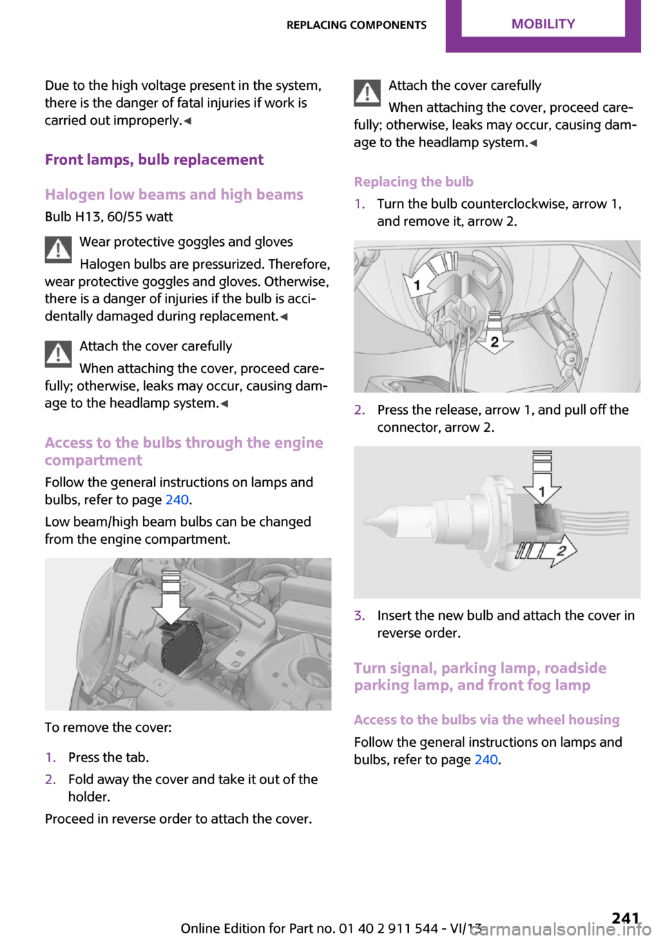
To remove the cover:
1.Press the tab.2.Fold away the cover and take it out of the
holder.
Proceed in reverse order to attach the cover.
Attach the cover carefully
When attaching the cover, proceed care‐
fully; otherwise, leaks may occur, causing dam‐
age to the headlamp system. ◀
Replacing the bulb1.Turn the bulb counterclockwise, arrow 1,
and remove it, arrow 2.2.Press the release, arrow 1, and pull off the
connector, arrow 2.3.Insert the new bulb and attach the cover in
reverse order.
Turn signal, parking lamp, roadside
parking lamp, and front fog lamp
Access to the bulbs via the wheel housing
Follow the general instructions on lamps and
bulbs, refer to page 240.
Seite 241Replacing componentsMobility241
Online Edition for Part no. 01 40 2 911 544 - VI/13
Page 251 of 282
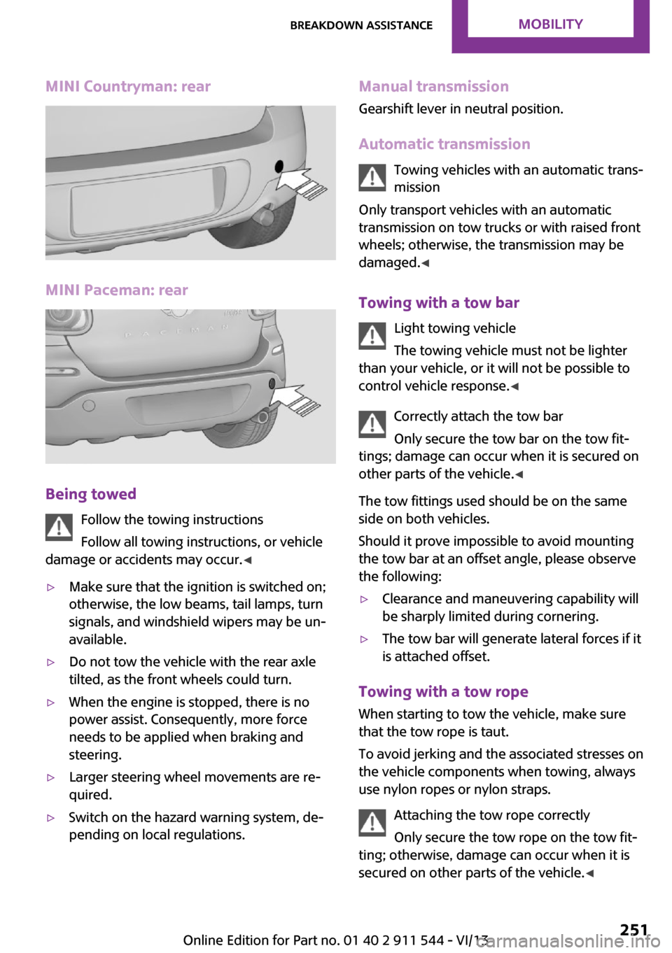
MINI Countryman: rear
MINI Paceman: rear
Being towedFollow the towing instructions
Follow all towing instructions, or vehicle
damage or accidents may occur. ◀
▷Make sure that the ignition is switched on;
otherwise, the low beams, tail lamps, turn
signals, and windshield wipers may be un‐
available.▷Do not tow the vehicle with the rear axle
tilted, as the front wheels could turn.▷When the engine is stopped, there is no
power assist. Consequently, more force
needs to be applied when braking and
steering.▷Larger steering wheel movements are re‐
quired.▷Switch on the hazard warning system, de‐
pending on local regulations.Manual transmission
Gearshift lever in neutral position.
Automatic transmission Towing vehicles with an automatic trans‐
mission
Only transport vehicles with an automatic
transmission on tow trucks or with raised front
wheels; otherwise, the transmission may be
damaged. ◀
Towing with a tow bar Light towing vehicle
The towing vehicle must not be lighter
than your vehicle, or it will not be possible to
control vehicle response. ◀
Correctly attach the tow bar
Only secure the tow bar on the tow fit‐
tings; damage can occur when it is secured on
other parts of the vehicle. ◀
The tow fittings used should be on the same
side on both vehicles.
Should it prove impossible to avoid mounting
the tow bar at an offset angle, please observe
the following:▷Clearance and maneuvering capability will
be sharply limited during cornering.▷The tow bar will generate lateral forces if it
is attached offset.
Towing with a tow rope
When starting to tow the vehicle, make sure
that the tow rope is taut.
To avoid jerking and the associated stresses on
the vehicle components when towing, always
use nylon ropes or nylon straps.
Attaching the tow rope correctly
Only secure the tow rope on the tow fit‐
ting; otherwise, damage can occur when it is
secured on other parts of the vehicle. ◀
Seite 251Breakdown assistanceMobility251
Online Edition for Part no. 01 40 2 911 544 - VI/13
Page 275 of 282
Internet page 6
Intersection, entering for navi‐ gation 137
J
Jump-starting 248
K Keyless Go, refer to Comfort Access 38
Keyless opening and closing, refer to Comfort Access 38
Key Memory, refer to Personal Profile 32
Key, refer to Remote control with integrated key 32
Kickdown– Automatic transmission with
Steptronic 66
Knee airbag 82
Knocking control 218
L Lamp and bulb replacement, bulb replacement 240
Lamp, replacing, refer to Lamp and bulb replace‐
ment 240
Lamps 78
Lamps, automatic headlamp control 78
Lamps, parking lamps/low beams 78
Language, changing on the Control Display 73
Lap-and-shoulder belt, refer to Safety belts 47
LATCH child restraint fixing system 54
Leather, care 256
Leather care 256
LEDs, light-emitting di‐ odes 240
Letters and numbers, enter‐
ing 24
License plate lamp, bulb re‐ placement 243
Light-alloy wheels, care 257
Light-emitting diodes, LEDs 240
Lighter– Socket 108
Lighting
– Instruments 80
Lighting, lamp and bulb re‐
placement 240
Lighting, vehicle, refer to Lamps 78
Light switch 78
Limit, refer to Speed limit 91
Lock buttons on doors, refer to Locking 37
Locking
– From the inside 37– From the outside 34– Setting the confirmation sig‐
nal 35– Without remote control, re‐
fer to Comfort Access 38
Locking, vehicle
– From the inside 36– From the outside 34
Longlife oils, alternative oil
types 235
Longlife oils, refer to Ap‐ proved engine oils 235
Low beams 78
Low beams
– Automatic 78
Low beams, automatic 78
Low beams, bulb replace‐ ment 241
Lower back support, refer to Lumbar support 46
Lumbar support 46
M
Main inspection, refer to Serv‐ ice requirements 74
Maintenance, refer to Service
booklet
Maintenance, refer to Service requirements 74
Maintenance require‐ ments 237
Maintenance system MINI 237
Malfunction– Automatic transmission with
Steptronic 67– Door lock 36– Fuel filler flap 216
Malfunction warnings, refer to
Check Control 75
Manual air distribu‐ tion 100, 102
Manual mode, automatic transmission with Step‐
tronic 66
Manual operation
– Door lock 36– Selector lever lock, auto‐
matic transmission 67
Manual operation, fuel filler
flap 216
Manual transmission 64
Map, destination entry 141
Map display in black and white 150
Map view 148
Marking on approved tires 227
Maximum cooling 102
Maximum speed, winter tires 228
Menu operation, onboard monitor 20
Menus, refer to Onboard monitor operating con‐
cept 21
Message list, traffic bulle‐ tins 149
Messages 205
Microfilter 101
Seite 275Everything from A to ZReference275
Online Edition for Part no. 01 40 2 911 544 - VI/13