navigation MINI Paceman 2014 Owner's Manual (Mini Connected)
[x] Cancel search | Manufacturer: MINI, Model Year: 2014, Model line: Paceman, Model: MINI Paceman 2014Pages: 282, PDF Size: 6.76 MB
Page 5 of 282
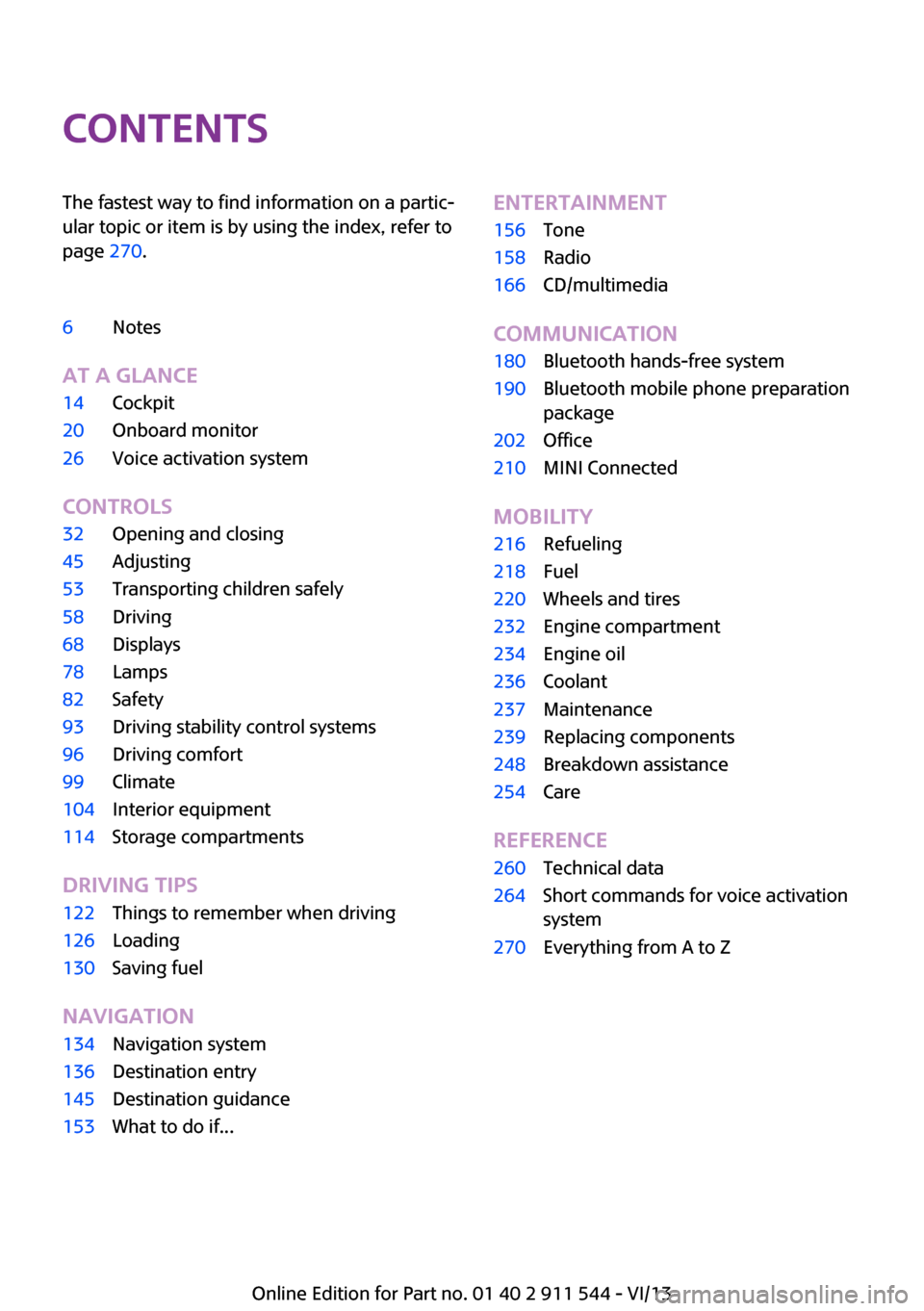
ContentsThe fastest way to find information on a partic‐
ular topic or item is by using the index, refer to
page 270.6Notes
At a glance
14Cockpit20Onboard monitor26Voice activation system
Controls
32Opening and closing45Adjusting53Transporting children safely58Driving68Displays78Lamps82Safety93Driving stability control systems96Driving comfort99Climate104Interior equipment114Storage compartments
Driving tips
122Things to remember when driving126Loading130Saving fuel
Navigation
134Navigation system136Destination entry145Destination guidance153What to do if...Entertainment156Tone158Radio166CD/multimedia
Communication
180Bluetooth hands-free system190Bluetooth mobile phone preparation
package202Office210MINI Connected
Mobility
216Refueling218Fuel220Wheels and tires232Engine compartment234Engine oil236Coolant237Maintenance239Replacing components248Breakdown assistance254Care
Reference
260Technical data264Short commands for voice activation
system270Everything from A to Z
Online Edition for Part no. 01 40 2 911 544 - VI/13
Page 13 of 282
At a glanceControlsDriving tipsNavigationEntertainmentCommunicationMobilityReferenceOnline Edition for Part no. 01 40 2 911 544 - VI/13
Page 31 of 282

At a glanceControlsDriving tipsNavigationEntertainmentCommunicationMobilityReferenceOnline Edition for Part no. 01 40 2 911 544 - VI/13
Page 70 of 282
To set the corresponding units of measure, re‐
fer to page 72.
Information in detail
Range
Displays the estimated cruising range available
with the remaining fuel.
It is calculated based on your driving style over
the last 18 miles/30 km.
Average fuel consumption
This is calculated for the period during which
the engine is running.
With the trip computer, refer to page 70, the
average consumption can be displayed for an
additional distance.
To reset the average consumption: press the
button on the turn indicator lever for ap‐
prox. 2 seconds.
Current fuel consumption Displays the current fuel consumption. You can
check whether you are currently driving in an
efficient and environmentally-friendly manner.
Average speed Periods in which the vehicle was parked and
the engine was switched off manually are not
included in the average speed calculations.
With the trip computer, refer to page 70, the
average speed can be displayed for an addi‐
tional distance.
To reset the average speed: press the button
on the turn indicator lever for approx. 2 sec‐
onds.
Displays on the Control Display Display the computer or trip computer on the
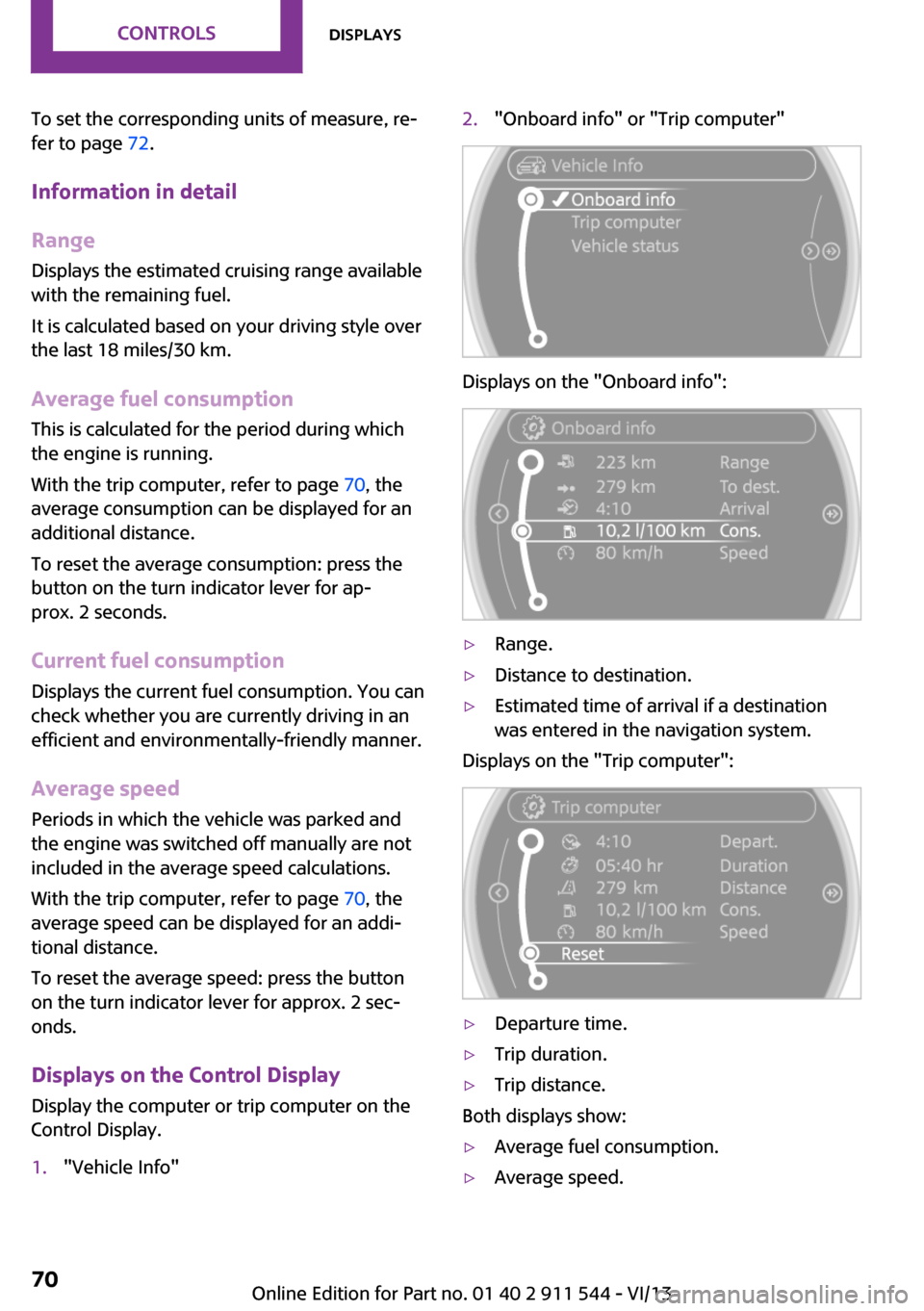
Control Display.1."Vehicle Info"2."Onboard info" or "Trip computer"
Displays on the "Onboard info":
▷Range.▷Distance to destination.▷Estimated time of arrival if a destination
was entered in the navigation system.
Displays on the "Trip computer":
▷Departure time.▷Trip duration.▷Trip distance.
Both displays show:
▷Average fuel consumption.▷Average speed.Seite 70ControlsDisplays70
Online Edition for Part no. 01 40 2 911 544 - VI/13
Page 83 of 282
Protective action
Airbags are not triggered in every impact situa‐
tion, e.g., in less severe accidents or rear-end
collisions.
Information on how to ensure the opti‐
mal protective effect of the airbags▷Keep at a distance from the airbags.▷Always grasp the steering wheel on the
steering wheel rim, holding your hands at
the 3 o'clock and 9 o'clock positions, to
keep the danger of injury to your hands or
arms as low as possible if the airbag is trig‐
gered.▷There should be no people, animals, or ob‐
jects between an airbag and a person.▷Do not use the cover of the front airbag on
the front passenger side as a storage area.▷Keep the dashboard and window on the
front passenger side clear, i.e., do not cover
with adhesive labels or coverings, and do
not attach holders such as for navigation in‐
struments and mobile phones.▷Make sure that the front passenger is sitting
correctly, i.e., keeps his or her feet and legs
in the footwell; otherwise, leg injuries can
occur if the front airbag is triggered.▷Do not place slip covers, seat cushions or
other objects on the front passenger seat
that are not approved specifically for seats
with integrated side airbags.▷Do not hang pieces of clothing, such as
jackets, over the backrests.▷Make sure that occupants keep their heads
away from the side airbag and do not rest
against the head airbag; otherwise, injuries
can occur if the airbags are triggered.▷Do not remove the airbag restraint system.▷Do not remove the steering wheel.▷Do not apply adhesive materials to the air‐
bag cover panels, cover them or modify
them in any way.▷Never modify either the individual compo‐
nents or the wiring in the airbag system.
This also applies to steering wheel covers,
the dashboard, the seats, the roof pillars
and the sides of the headliner. ◀
Even when all instructions are followed closely,
injury from contact with the airbags cannot be
ruled out in certain situations.
The ignition and inflation noise may lead to
short-term and, in most cases, temporary hear‐
ing impairment in sensitive individuals.
In the case of a malfunction, deactivation
and after triggering of the airbags
Do not touch the individual components imme‐
diately after the system has been triggered;
otherwise, there is the danger of burns.
Only have the airbags checked, repaired or dis‐
mantled and the airbag generator scrapped by
your service center or a workshop that has the
necessary authorization for handling explo‐
sives.
Non-professional attempts to service the sys‐
tem could lead to failure in an emergency or
undesired triggering of the airbag, either of
which could result in injury. ◀
Warning notices and information about the air‐
bags can also be found on the sun visors.
Automatic deactivation of the front
passenger airbags
The system determines whether the front pas‐
senger seat is occupied by measuring the elec‐
trical resistance of the human body.
The front, side, and knee airbags on the front
passenger side are activated or deactivated ac‐
cordingly by the system.
The indicator lamp above the interior rearview
mirror, refer to page 84, shows the current
status of the front passenger airbags, deacti‐
vated or activated.
Seite 83SafetyControls83
Online Edition for Part no. 01 40 2 911 544 - VI/13
Page 115 of 282

Opening
Turn the switch in the direction of the arrow.ClosingMove the switch to the vertical position by
turning it in the opposite direction of the arrow.
Depending on the temperature setting of the
air conditioning or automatic climate control,
high temperatures may occur in the glove com‐
partment.
USB interface for data transfer Updating the navigation data, refer to
page 134, from the USB medium via the USB
interface in the glove compartment.
Observe the following when connecting:
▷Do not use force when plugging the con‐
nector into the USB interface.▷Do not connect devices such as fans or
lamps to the USB interface.▷Do not connect USB hard drives.▷Do not use the USB interface to recharge
external devices.
Center armrest
The center armrest between the front seats
contains a storage compartment or a cover for
the snap-in adapter, refer to page 200, de‐
pending on the equipment.
The center armrest between the rear seats con‐
tains a storage compartment.
Do not position tall accessory parts directly on
the center rail of the center armrest; otherwise,
they may be damaged when the center arm‐
rest is opened or closed.
Center armrest front
Opening
Press the button, arrow, and pull up the lid.
MINI Paceman: center armrest, rear
Removing
The rear center armrest can be removed to en‐
large the loading area.
1.Turn the handwheel counterclockwise all
the way to open it, arrow 1.2.Push the center armrest back slightly in the
base plate, arrow 2.3.Lift the center armrest at the front and
pivot it out.Seite 115Storage compartmentsControls115
Online Edition for Part no. 01 40 2 911 544 - VI/13
Page 121 of 282

At a glanceControlsDriving tipsNavigationEntertainmentCommunicationMobilityReferenceOnline Edition for Part no. 01 40 2 911 544 - VI/13
Page 133 of 282
At a glanceControlsDriving tipsNavigationEntertainmentCommunicationMobilityReferenceOnline Edition for Part no. 01 40 2 911 544 - VI/13
Page 134 of 282
Navigation systemVehicle equipment
This chapter describes all series equipment as
well as country-specific and special equipment
offered for this model series.Therefore, it also
describes equipment that may not be found in
your vehicle, for instance due to the selected
special equipment or the country version. This
also applies to safety-related functions and sys‐
tems.
General information The navigation system can determine the pre‐
cise position of the vehicle, with the aid of sat‐
ellites and vehicle sensors, and can reliably
guide you to every entered destination.
Entries in stationary vehicle
Enter data only when the vehicle is sta‐
tionary, and always give priority to the applica‐
ble traffic regulations in the event of any con‐
tradiction between traffic and road conditions
and the instructions issued by the navigation
system. Failure to take to this precaution can
place you in violation of the law and put vehicle
occupants and other road users in danger. ◀
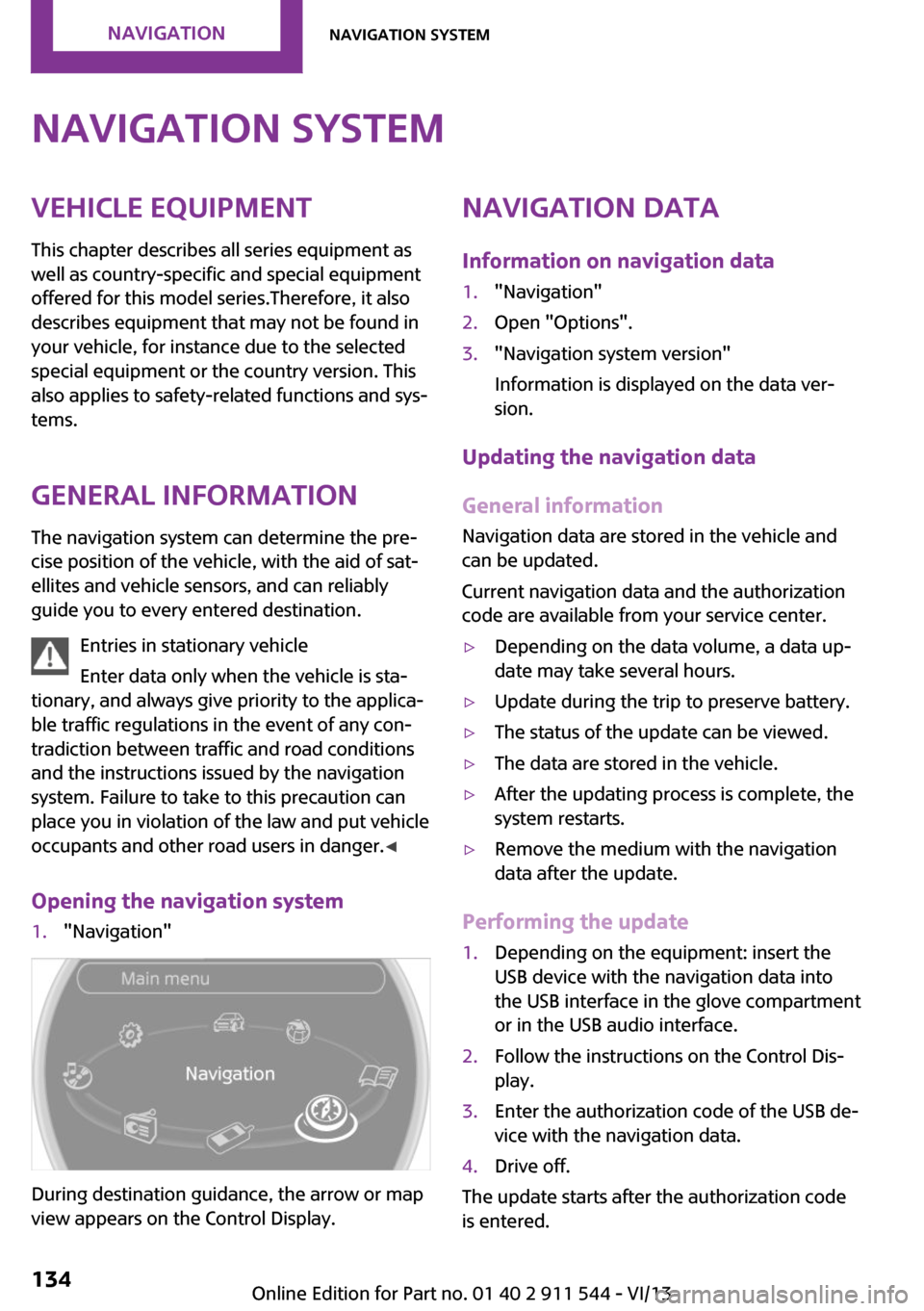
Opening the navigation system1."Navigation"
During destination guidance, the arrow or map
view appears on the Control Display.
Navigation data
Information on navigation data1."Navigation"2.Open "Options".3."Navigation system version"
Information is displayed on the data ver‐
sion.
Updating the navigation data
General information
Navigation data are stored in the vehicle and
can be updated.
Current navigation data and the authorization
code are available from your service center.
▷Depending on the data volume, a data up‐
date may take several hours.▷Update during the trip to preserve battery.▷The status of the update can be viewed.▷The data are stored in the vehicle.▷After the updating process is complete, the
system restarts.▷Remove the medium with the navigation
data after the update.
Performing the update
1.Depending on the equipment: insert the
USB device with the navigation data into
the USB interface in the glove compartment
or in the USB audio interface.2.Follow the instructions on the Control Dis‐
play.3.Enter the authorization code of the USB de‐
vice with the navigation data.4.Drive off.
The update starts after the authorization code
is entered.
Seite 134NavigationNavigation system134
Online Edition for Part no. 01 40 2 911 544 - VI/13
Page 135 of 282
When the update is completed, the system re‐
starts.Seite 135Navigation systemNavigation135
Online Edition for Part no. 01 40 2 911 544 - VI/13