traction control MINI Paceman 2014 Owner's Manual (Mini Connected)
[x] Cancel search | Manufacturer: MINI, Model Year: 2014, Model line: Paceman, Model: MINI Paceman 2014Pages: 282, PDF Size: 6.76 MB
Page 18 of 282
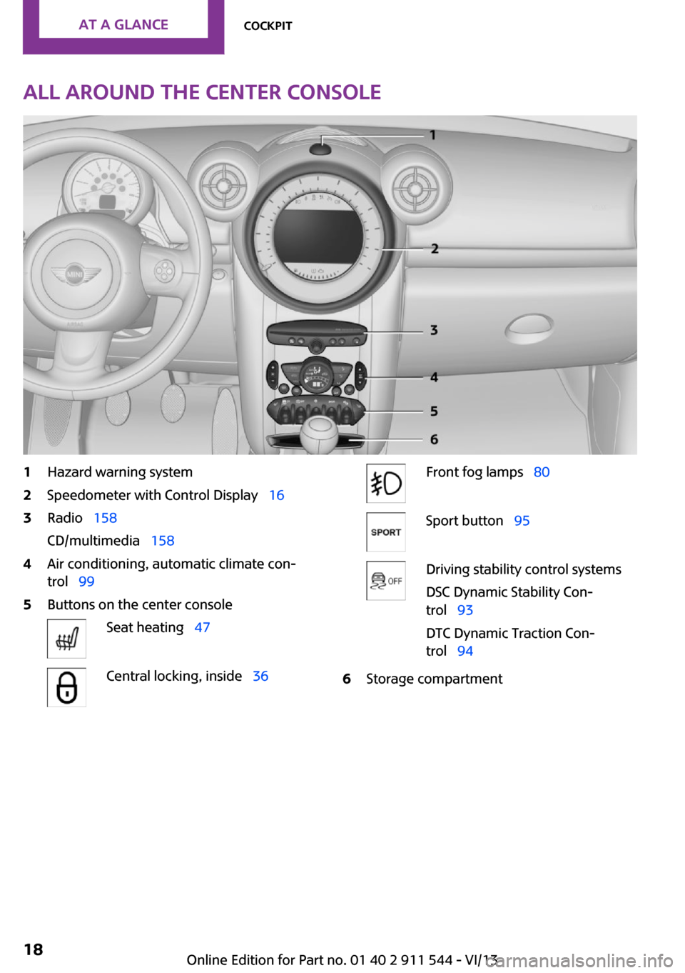
All around the center console1Hazard warning system2Speedometer with Control Display 163Radio 158
CD/multimedia 1584Air conditioning, automatic climate con‐
trol 995Buttons on the center consoleSeat heating 47Central locking, inside 36Front fog lamps 80Sport button 95Driving stability control systems
DSC Dynamic Stability Con‐
trol 93
DTC Dynamic Traction Con‐
trol 946Storage compartmentSeite 18At a glanceCockpit18
Online Edition for Part no. 01 40 2 911 544 - VI/13
Page 93 of 282
Driving stability control systemsVehicle equipment
This chapter describes all series equipment as
well as country-specific and special equipment
offered for this model series.Therefore, it also
describes equipment that may not be found in
your vehicle, for instance due to the selected
special equipment or the country version. This
also applies to safety-related functions and sys‐
tems.
Antilock Brake System
ABS
ABS prevents locking of the wheels duringbraking.
Steerability is maintained even during full brak‐
ing. This increases active driving safety.
ABS is operational every time you start the en‐
gine.
Electronic brake-force distribution EBVThe system controls the brake pressure in the
rear wheels to ensure stable braking behavior.
CBC Cornering Brake Control
When braking in curves or during a lane
change, driving stability and steering response
are improved further.
Brake assistant When the brakes are applied rapidly, this sys‐
tem automatically produces the maximum
braking force boost. In this way, the system
helps keep the braking distance as short as
possible. This system utilizes all of the benefits
provided by ABS.Do not reduce the pressure on the brake pedal
for the duration of full braking.
Dynamic Stability Con‐
trol DSC
The concept
DSC prevents traction loss in the driving wheels
when driving away and accelerating.
DSC also recognizes unstable vehicle condi‐
tions, such as fishtailing or nose-diving. Subject
to physical limits, DSC helps to keep the vehicle
on a steady course by reducing engine speed
and by applying brakes to the individual
wheels.
DSC is operational every time you start the en‐
gine.
Adjust your driving style to the situation
An appropriate driving style is always the
responsibility of the driver.
The laws of physics cannot be repealed, even
with DSC.
Do not reduce the additional safety margin
with a risky driving style, as otherwise there is a
risk of an accident. ◀
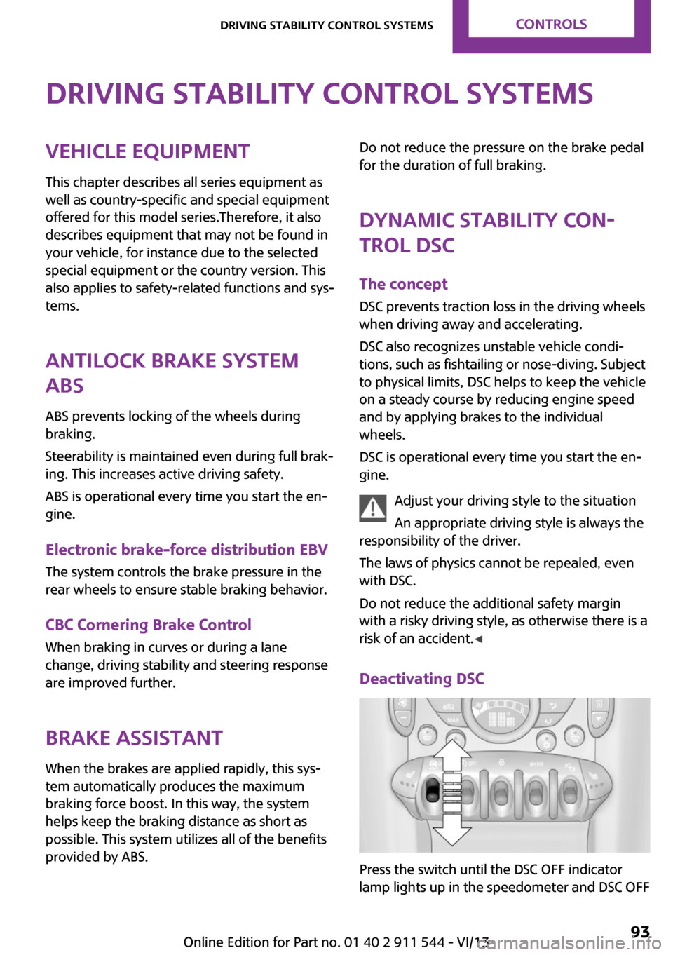
Deactivating DSC
Press the switch until the DSC OFF indicator
lamp lights up in the speedometer and DSC OFF
Seite 93Driving stability control systemsControls93
Online Edition for Part no. 01 40 2 911 544 - VI/13
Page 94 of 282
appears in the tachometer. DSC is deactivated.
Intervening measures to stabilize the vehicle
and give it forward momentum are no longer
executed.
When driving with snow chains or to rock the
vehicle free of snow, it may be useful to deacti‐
vate DSC temporarily.
To increase vehicle stability, activate DSC again
as soon as possible.
Activating DSC
Press the switch again; the DSC indicator lamps
in the display elements go out.
Indicator/warning lamps The indicator lamp in the tachometer
flashes: DSC is controlling the drive
forces and brake forces.
The indicator lamp lights up: DSC and DTC has
failed.
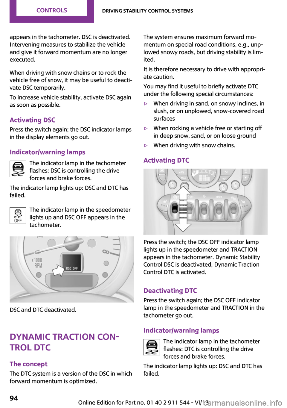
The indicator lamp in the speedometer
lights up and DSC OFF appears in the
tachometer.
DSC and DTC deactivated.
Dynamic Traction Con‐
trol DTC
The concept
The DTC system is a version of the DSC in which
forward momentum is optimized.
The system ensures maximum forward mo‐
mentum on special road conditions, e.g., unp‐
lowed snowy roads, but driving stability is lim‐
ited.
It is therefore necessary to drive with appropri‐
ate caution.
You may find it useful to briefly activate DTC
under the following special circumstances:▷When driving in sand, on snowy inclines, in
slush, or on unplowed, snow-covered road
surfaces▷When rocking a vehicle free or starting off
in deep snow, sand, or on loose ground▷When driving with snow chains.
Activating DTC
Press the switch; the DSC OFF indicator lamp
lights up in the speedometer and TRACTION
appears in the tachometer. Dynamic Stability
Control DSC is deactivated, Dynamic Traction
Control DTC is activated.
Deactivating DTC Press the switch again; the DSC OFF indicator
lamp in the speedometer and TRACTION in the
tachometer go out.
Indicator/warning lamps The indicator lamp in the tachometer
flashes: DTC is controlling the drive
forces and brake forces.
The indicator lamp lights up: DSC and DTC has
failed.
Seite 94ControlsDriving stability control systems94
Online Edition for Part no. 01 40 2 911 544 - VI/13
Page 95 of 282
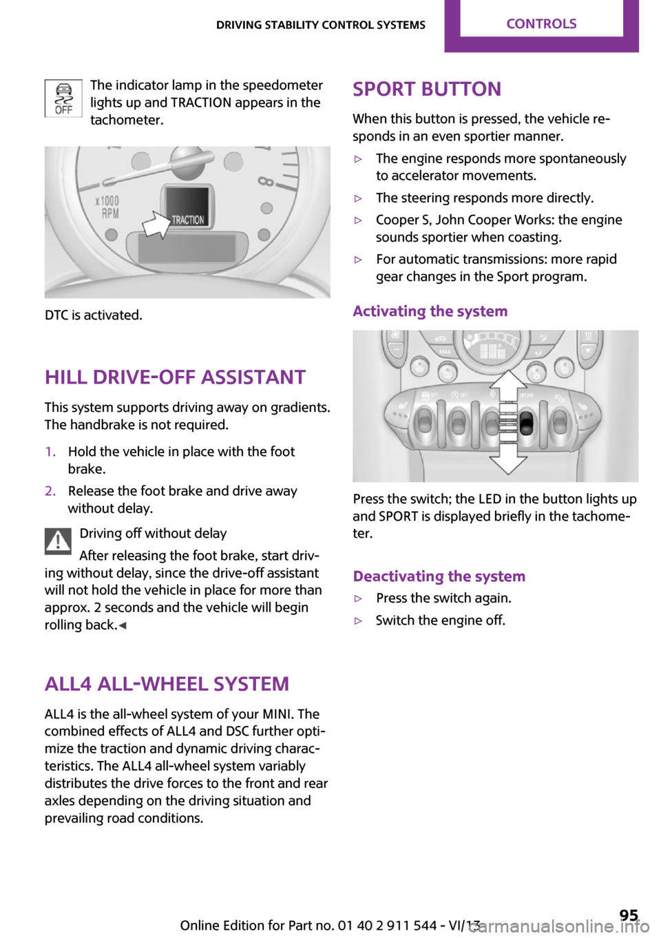
The indicator lamp in the speedometer
lights up and TRACTION appears in the
tachometer.
DTC is activated.
Hill drive-off assistant This system supports driving away on gradients.
The handbrake is not required.
1.Hold the vehicle in place with the foot
brake.2.Release the foot brake and drive away
without delay.
Driving off without delay
After releasing the foot brake, start driv‐
ing without delay, since the drive-off assistant
will not hold the vehicle in place for more than
approx. 2 seconds and the vehicle will begin
rolling back. ◀
ALL4 all-wheel system
ALL4 is the all-wheel system of your MINI. The
combined effects of ALL4 and DSC further opti‐
mize the traction and dynamic driving charac‐
teristics. The ALL4 all-wheel system variably
distributes the drive forces to the front and rear
axles depending on the driving situation and
prevailing road conditions.
Sport button
When this button is pressed, the vehicle re‐
sponds in an even sportier manner.▷The engine responds more spontaneously
to accelerator movements.▷The steering responds more directly.▷Cooper S, John Cooper Works: the engine
sounds sportier when coasting.▷For automatic transmissions: more rapid
gear changes in the Sport program.
Activating the system
Press the switch; the LED in the button lights up
and SPORT is displayed briefly in the tachome‐
ter.
Deactivating the system
▷Press the switch again.▷Switch the engine off.Seite 95Driving stability control systemsControls95
Online Edition for Part no. 01 40 2 911 544 - VI/13
Page 125 of 282
Driving on poor roadsYour MINI with ALL4 all-wheel drive feels com‐
fortable on all streets and roads. It combines an
all-wheel drive system with the advantages of a
normal passenger car.
Do not drive on unpaved terrain
Do not drive on unpaved terrain, as oth‐
erwise the vehicle may be damaged. ◀
For your own safety and the safety of passen‐
gers and the vehicle, adhere to the following
points:▷Familiarize yourself with the vehicle before
driving; never take risks.▷Adjust speeds according to road conditions.
The steeper and rougher the road surface
is, the lower the speed should be.▷When driving on steep uphill and downhill
grades: the engine oil and coolant should
be filled nearly to the MAX mark.▷Watch for stones, holes, and other obsta‐
cles and drive around these where possible.▷On bumps and rough roads, avoid contact
between the vehicle body and the ground.
The maximum ground clearance is 6 in‐
ches/15 cm and may vary with the loaded
cargo.▷When driving through water, do not exceed
the maximum water height of 12 in‐
ches/30 cm and drive at walking speed.▷After driving through water, press on the
brake pedal several times at low speeds to
dry the brakes.▷Depending on the prevailing terrain, acti‐
vate Dynamic Traction Control DTC briefly,
refer to page 94.▷When the wheels spin, accelerate to enable
the driving stability control systems to dis‐
tribute the drive force to the individual
wheels.After driving on poor roads
Adhere to the following points to ensure vehi‐
cle safety:▷Remove excessive accumulations of dirt
and mud from the vehicle body.▷Clear mud, snow, ice, etc., from the wheels
and tires and check for damage.Seite 125Things to remember when drivingDriving tips125
Online Edition for Part no. 01 40 2 911 544 - VI/13
Page 210 of 282
MINI ConnectedVehicle equipmentThis chapter describes all series equipment as
well as country-specific and special equipment
offered for this model series.Therefore, it also
describes equipment that may not be found in
your vehicle, for instance due to the selected
special equipment or the country version. This
also applies to safety-related functions and sys‐
tems.
At a glance The concept
Certain software applications of a suitable mo‐
bile phone can be integrated in the vehicle.
These software applications are displayed on
the Control Display.
They are operated via the onboard monitor.
The scope of the software applications may
vary by country.
Requirements▷The mobile phone is suitable.▷The mobile phone operating system sup‐
ports the software applications of MINI
Connected.▷Software applications are installed on the
mobile phone and ready to use.▷Corresponding mobile wireless contract.
Any additionally incurred costs are not a
part of MINI Connected.
Information about suitable mobile phones,
available software applications, and their instal‐
lation can be obtained at www.mini.com/
connectivity or from the service center.
Create the entries.
Make entries only when traffic and road
conditions allow. Otherwise, the vehicle occu‐
pants and other road users may be put in dan‐
ger because of the distraction from driving.
For reasons of safety, some software applica‐
tions are usable only while the vehicle is sta‐
tionary. ◀
Software applications
Use only software applications approved
by the manufacturer of your MINI; otherwise,
malfunctions may occur. ◀
Connecting the mobile
phone
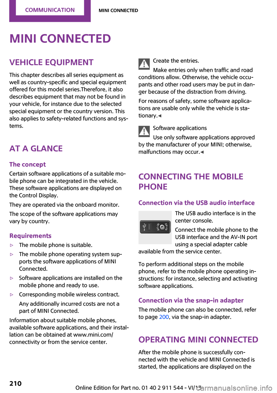
Connection via the USB audio interface The USB audio interface is in the
center console.
Connect the mobile phone to the
USB interface and the AV-IN port
using a special adapter cable
available from the service center.
To perform additional steps on the mobile
phone, refer to the mobile phone operating in‐
structions: for instance, selecting and activating
software applications.
Connection via the snap-in adapter
The mobile phone can also be connected, refer
to page 200, via the snap-in adapter.
Operating MINI Connected After the mobile phone is successfully con‐
nected with the vehicle and MINI Connected is
started, the applications are displayed on theSeite 210CommunicationMINI Connected210
Online Edition for Part no. 01 40 2 911 544 - VI/13
Page 225 of 282
Conform to Federal Safety Requirements
All passenger car tires must conform to
Federal Safety Requirements in addition to
these grades. ◀
Treadwear
The treadwear grade is a comparative rating based on the wear rate of the tire when tested
under controlled conditions on a specified gov‐
ernment test course. For example, a tire graded
150 would wear one and one-half (1 1/2) times
as well on the government course as a tire graded 100. The relative performance of tires
depends upon the actual conditions of their
use, however, and may depart significantly
from the norm due to variations in driving hab‐
its, service practices and differences in road
characteristics and climate.
TractionThe traction grades, from highest to lowest, are
AA, A, B, and C.
Those grades represent the tire’s ability to stop
on wet pavement as measured under control‐
led conditions on specified government test
surfaces of asphalt and concrete. A tire marked
C may have poor traction performance.
The traction grade assigned to this tire is based
on straight-ahead braking traction tests, and
does not include acceleration, cornering, hy‐
droplaning, or peak traction characteristics.
Temperature
The temperature grades are A, the highest, B,
and C, representing the tire’s resistance to the
generation of heat and its ability to dissipate
heat when tested under controlled conditions
on a specified indoor laboratory test wheel.
Sustained high temperature can cause the ma‐
terial of the tire to degenerate and reduce tire
life, and excessive temperature can lead to
sudden tire failure. The grade C corresponds to
a level of performance which all passenger car
tires must meet under the Federal Motor Vehi‐cle Safety Standard No. 109. Grades B and A
represent higher levels of performance on the
laboratory test wheel than the minimum re‐
quired by law.
Temperature grade for this tire
The temperature grade for this tire is es‐
tablished for a tire that is properly inflated and
not overloaded. Excessive speed, underinfla‐
tion, or excessive loading, either separately or
in combination, can cause heat buildup and
possible tire failure. ◀
RSC – Run-flat tires
The symbol identifying run-flat tires is a circle
with the letters RSC on the sidewall, refer to
page 228.
M+S
Winter and all-season tires.
These have better winter properties than
summer tires.
XL
Designation for specially reinforced tires.
Tire treadSummer tiresThe tread depth should not be less than
0.12 in/3 mm, although European legislation,
for example, requires a minimum tread depth
of only 0.063 in/1.6 mm. At tread depths less
than 0.12 in/3 mm, there is a great danger of
hydroplaning even in low water depths and at
raised speeds.
Winter tires
The suitability of winter tires for winter driving
is reduced noticeably when their tread depth
becomes less than 0.16 in/4 mm.Seite 225Wheels and tiresMobility225
Online Edition for Part no. 01 40 2 911 544 - VI/13
Page 272 of 282
Consumption, refer to Aver‐age fuel consumption 70
Contacts 187, 203
Control Display 20
Control Display, care 257
Control Display, settings 73
Controls and displays 14
Control systems, driving stabil‐ ity 93
Convenient operation– Windows 34
Coolant temperature 69
Cooling function, switching on and off 103
Cooling, maximum 102
Cornering Brake Control, CBC 93
Corrosion on brake discs 124
Cradle for telephone or mobile phone, refer to Snap-in
adapter 200
Cruise control 96
Cupholders 108
Current fuel consumption 70
Current location, storing 138
Curve lights, refer to Adaptive Light Control 80
Cylinders, number of, refer to Engine data 260
D
Dashboard lighting, refer to Instrument lighting 80
Dashboard, refer to Cock‐ pit 14
Dashboard, refer to Dis‐ plays 16
Data, technical 260
Date
– Date format 73– Setting 73
Daytime running lights 79
Decorative trim, care 257
Defogging windows 100
Defroster
– Rear window 100, 103Defrosting windows 100
Defrost setting, refer to De‐ frosting windows 100
Destination entry via the ad‐ dress book 138
Destination guidance with in‐ termediate destinations 143
Destination input, naviga‐ tion 136
Digital compass 106
Digital radio 159
Dip stick, engine oil 234
Directional indicators, refer to Turn signals 61
Displacement, refer to Engine data 260
Display lighting, refer to In‐ strument lighting 80
Displays 16
Displays and controls 14
Displays, care 257
Displays, cleaning 257
Displays, refer to Instrument cluster 16
Disposal– Remote control battery 41
Distance warning, refer to
Park Distance Control
PDC 97
Door key, refer to Remote control with integrated
key 32
Door lock 35
Door lock, confirmation sig‐ nals 35
Doors, manual operation 36
Doors, unlocking and locking
– Confirmation signals 35– From the inside 36– From the outside 34
DOT Quality Grades 224
Drive-off assistant, refer to Hill drive-off assistant 95
Driving notes, breaking in 122
Driving off on hills, refer to Hill drive-off assistant 95
Driving on poor roads 125
Driving stability control sys‐ tems 93
Driving tips, refer to Driving notes 122
Dry air, refer to Cooling func‐ tion 103
DSC Dynamic Stability Con‐ trol 93
DTC Dynamic Traction Con‐ trol 94
DTMF suffix dialing 185, 197
Dynamic destination guid‐ ance 152
Dynamic Stability Control DSC 93
Dynamic Traction Control DTC 94
E Electrical malfunction– Door lock 36– Fuel filler flap 216
Electronic brake-force distri‐
bution 93
Electronic Stability Program ESP, refer to Dynamic Stabil‐
ity Control DSC 93
Emergency activation
– Automatic transmission, re‐
fer to Overriding selector
lever lock 67
Emergency operation, fuel
filler flap, unlocking man‐
ually 216
Emergency operation, refer to
Manual operation
– Door lock 36
Energy, saving, refer to Saving
fuel 130
Engine, breaking in 122
Engine compartment 232
Engine oil, adding 234
Engine oil, additives, refer to Approved engine oils 235
Seite 272ReferenceEverything from A to Z272
Online Edition for Part no. 01 40 2 911 544 - VI/13
Page 279 of 282
Tires– Flat tire 86– Inflation pressure 220– Inflation pressure loss 89– Pressure monitoring, refer to
Tire Pressure Monitor
TPM 87
Tires, breaking in 122
Tires, changing 227
Tires, condition 225
Tires, damage 226
Tire size 224
Tires, minimum tread 226
Tires, retreaded tires 227
Tires, storage 228
Tire tread 225
Toll roads, route 145
Tone 156
Torque, refer to Engine data 260
Towing another vehicle 250
Towing, being towed 250
Town/city, navigation 136
Tow-starting 250
TPM, refer to Tire Pressure Monitor 87
Traction control 94
Traffic bulletins, naviga‐ tion 149
Transmission
– Overriding selector lever
lock in case of automatic
transmission with Step‐
tronic 67
Transmission lock
– Refer to Changing selector
lever positions 65
Transmission, manual 64
Transporting children safely 53
Treble, tone 156
Trip-distance counter, refer to Trip odometer 68
Triple turn signal activa‐ tion 61
Trip odometer 68
Trips, planning 143
Trunk lid, refer to Tailgate 37
Trunk, refer to Cargo area 37
Turning lamps, refer to Adap‐ tive Light Control 80
Turn signal– Indicator lamp 16
Turn signal, bulb replace‐
ment 241
Turn signals 61
Turn signals, triple turn signal activation 61
U
Uniform Tire Quality Grading/ UTQG 224
Unintentional alarms, avoid‐ ing 41
Units
– Average fuel consump‐
tion 72– Temperature 72
Units of measure, changing on
Control Display 72
Universal remote control 104
Unlocking
– From the inside 37– From the outside 34– Tailgate 39– Without remote control, re‐
fer to Comfort Access 38
Update, software 176
Upholstery care 256
Upholstery material care 256
V
Vehicle
– Identification num‐
ber 180, 190
Vehicle battery 246
Vehicle, breaking in 122
Vehicle care 255
Vehicle care, refer to Care 254
Vehicle equipment 6
Vehicle paintwork, care 256
Vehicle storage 257
Vehicle, switching off 60
Vehicle wash 254
Ventilation– Air conditioning 103
Version of the navigation
data 134
Video playback, iPhone 172
Video playback, snap-in adapter 172
Voice activation
– Navigation 142
Voice activation, short com‐
mands 264
Voice activation system 26
Volume, setting 156
W Warning and indicator lamps 17
Warning messages, refer to Check Control 75
Warning signal volumes 156
Warning triangle 248
Washer/wiper system 61
Washer/wiper system, rain sensor 62
Washer/wiper system, washer fluid 64
Washer fluid 64
Washer fluid reservoir 64
Washing, vehicle 254
Welcome lamps 79
Wheel change 245
Wheels and tires 220
Wheels, changing 227
Wheels, Flat Tire Monitor FTM 85
Windows
– Closing 43– Convenient operation 34– Opening 43
Windows, care 255
Windows, defrosting and de‐ fogging 100
Windows, pinch protection 43
Seite 279Everything from A to ZReference279
Online Edition for Part no. 01 40 2 911 544 - VI/13