start stop button MINI Paceman 2014 Owner's Manual
[x] Cancel search | Manufacturer: MINI, Model Year: 2014, Model line: Paceman, Model: MINI Paceman 2014Pages: 218, PDF Size: 5.5 MB
Page 15 of 218
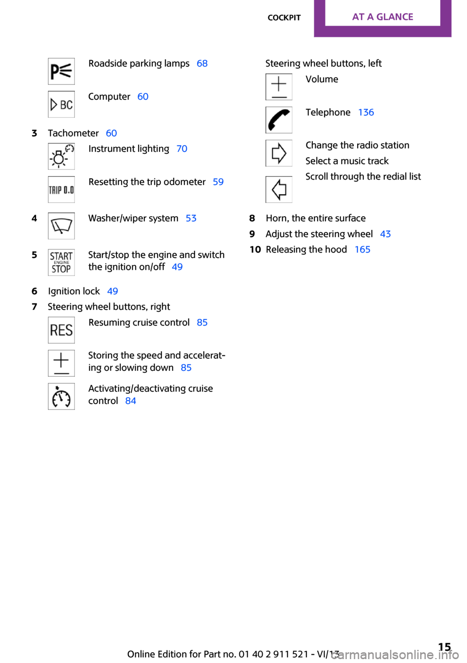
Roadside parking lamps 68Computer 603Tachometer 60Instrument lighting 70Resetting the trip odometer 594Washer/wiper system 535Start/stop the engine and switch
the ignition on/off 496Ignition lock 497Steering wheel buttons, rightResuming cruise control 85Storing the speed and accelerat‐
ing or slowing down 85Activating/deactivating cruise
control 84Steering wheel buttons, leftVolumeTelephone 136Change the radio station
Select a music track
Scroll through the redial list8Horn, the entire surface9Adjust the steering wheel 4310Releasing the hood 165Seite 15CockpitAt a glance15
Online Edition for Part no. 01 40 2 911 521 - VI/13
Page 31 of 218
If a remote control accidentally left in the cargo
area is detected in the locked vehicle after the
tailgate is closed, the tailgate opens again
slightly. The hazard warning system flashes and
an acoustic signal sounds.
Power windows and electrical glass
sunroof
When the engine is switched off, the windows
and the sunroof can be operated as long as
neither the doors nor the tailgate are opened.
When the door and tailgate are closed again
and the remote control is detected inside the
vehicle, the windows and the sunroof can be
operated again.
Insert the remote control into the ignition lock
to be able to operate the windows and the sun‐
roof while the engine is switched off and the
doors are open.
Switching on the radio ready state Press the Start/Stop button to switch on the
radio ready state, refer to page 49.
Do not depress the brake or the clutch; other‐
wise, the engine will start.
Starting the engine The engine can be started or the ignition can
be switched on, refer to page 49, when a re‐
mote control is inside the vehicle. It is not nec‐
essary to insert a remote control into the igni‐
tion lock.
Switching off the engine in cars with
automatic transmission
The engine can only be switched off with the
selector lever in position P, refer to page 56.
To switch off the engine with the selector lever
in position N, the remote control must be in‐
serted in the ignition lock.Before driving a vehicle with automatic
transmission into a car wash1.Insert the remote control into the ignition
switch.2.Depress the brake pedal.3.Move the selector lever to position N.4.Switch the engine off.
The vehicle can roll.
Malfunction The Comfort Access functions can be disturbed
by local radio waves, such as by a mobile
phone in the immediate vicinity of the remote
control or when a mobile phone is being
charged in the vehicle.
If this occurs, open or close the vehicle using
the buttons on the remote control or use the
integrated key in the door lock.
To start the engine afterward, insert the remote
control into the ignition switch.
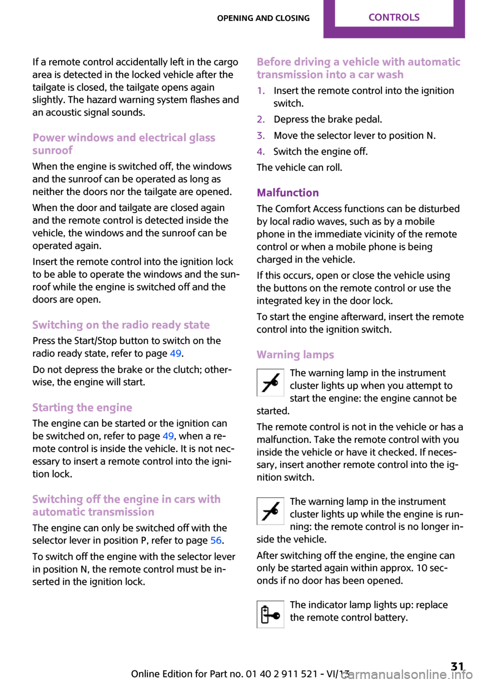
Warning lamps The warning lamp in the instrument
cluster lights up when you attempt to
start the engine: the engine cannot be
started.
The remote control is not in the vehicle or has a
malfunction. Take the remote control with you
inside the vehicle or have it checked. If neces‐
sary, insert another remote control into the ig‐
nition switch.
The warning lamp in the instrument
cluster lights up while the engine is run‐
ning: the remote control is no longer in‐
side the vehicle.
After switching off the engine, the engine can
only be started again within approx. 10 sec‐
onds if no door has been opened.
The indicator lamp lights up: replace
the remote control battery.
Seite 31Opening and closingControls31
Online Edition for Part no. 01 40 2 911 521 - VI/13
Page 49 of 218
DrivingVehicle equipmentThis chapter describes all series equipment as
well as country-specific and special equipment
offered for this model series.Therefore, it also
describes equipment that may not be found in
your vehicle, for instance due to the selected
special equipment or the country version. This
also applies to safety-related functions and sys‐
tems.
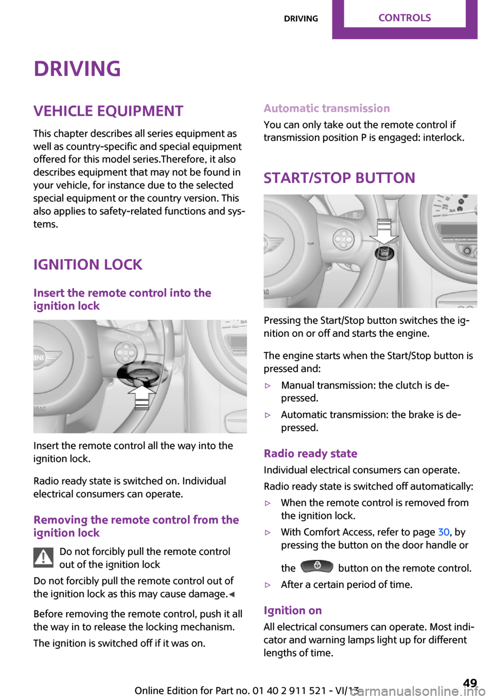
Ignition lock Insert the remote control into the
ignition lock
Insert the remote control all the way into the
ignition lock.
Radio ready state is switched on. Individual
electrical consumers can operate.
Removing the remote control from the
ignition lock
Do not forcibly pull the remote control
out of the ignition lock
Do not forcibly pull the remote control out of
the ignition lock as this may cause damage. ◀
Before removing the remote control, push it all
the way in to release the locking mechanism.
The ignition is switched off if it was on.
Automatic transmission
You can only take out the remote control if
transmission position P is engaged: interlock.
Start/Stop button
Pressing the Start/Stop button switches the ig‐
nition on or off and starts the engine.
The engine starts when the Start/Stop button is
pressed and:
▷Manual transmission: the clutch is de‐
pressed.▷Automatic transmission: the brake is de‐
pressed.
Radio ready state
Individual electrical consumers can operate.
Radio ready state is switched off automatically:
▷When the remote control is removed from
the ignition lock.▷With Comfort Access, refer to page 30, by
pressing the button on the door handle or
the
button on the remote control.
▷After a certain period of time.
Ignition on All electrical consumers can operate. Most indi‐
cator and warning lamps light up for different
lengths of time.
Seite 49DrivingControls49
Online Edition for Part no. 01 40 2 911 521 - VI/13
Page 50 of 218
To save battery power when the engine is off,
switch off the ignition and any unnecessary
electronic systems/power consumers.
Radio ready state and ignition off All indicator and warning lamps in the displays
go out.
The ignition switches off automatically when
the driver's door is opened. Pressing the Start/
Stop button again switches the ignition back
on.
For example, the ignition is not switched off in
the following situations:▷Depress the clutch or brake pedal.▷The low beams are switched on
Starting the engine
General information Enclosed areas
Do not let the engine run in enclosed
areas; otherwise, breathing of exhaust fumes
may lead to loss of consciousness and death.
The exhaust gases contain carbon monoxide,
an odorless and colorless but highly toxic gas. ◀
Unattended vehicle
Do not leave the car unattended with the
engine running; otherwise, it presents a poten‐
tial source of danger.
Before leaving the car with the engine running,
shift to neutral or engage transmission posi‐
tion P and set the handbrake firmly; otherwise,
the vehicle may begin to roll. ◀
Frequent starting in quick succession
Avoid repeated futile attempts at starting
the car and avoid starting the car frequently in
quick succession. Otherwise, the fuel is not
burned or is inadequately burned, and there is
the danger of overheating and damaging the
catalytic converter. ◀
Do not wait for the engine to warm-up while
the vehicle remains stationary; start driving
right away, but at moderate engine speeds.
Do not depress the accelerator when starting
the engine.
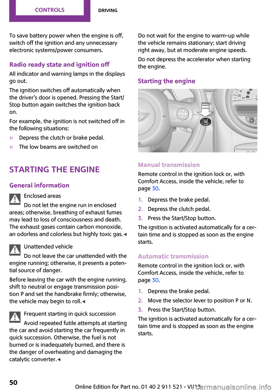
Starting the engine
Manual transmission
Remote control in the ignition lock or, with
Comfort Access, inside the vehicle, refer to
page 30.
1.Depress the brake pedal.2.Depress the clutch pedal.3.Press the Start/Stop button.
The ignition is activated automatically for a cer‐
tain time and is stopped as soon as the engine
starts.
Automatic transmission
Remote control in the ignition lock or, with
Comfort Access, inside the vehicle, refer to
page 30.
1.Depress the brake pedal.2.Move the selector lever to position P or N.3.Press the Start/Stop button.
The ignition is activated automatically for a cer‐
tain time and is stopped as soon as the engine
starts.
Seite 50ControlsDriving50
Online Edition for Part no. 01 40 2 911 521 - VI/13
Page 51 of 218
Engine stop
General information Take the remote control with you
Take the remote control with you when
leaving the vehicle so that children, for exam‐
ple, cannot operate the windows and injure
themselves. ◀
Set the handbrake and further secure the
vehicle as required
Set the handbrake firmly when parking; other‐
wise, the vehicle may roll. On steep upward
and downward inclines, further secure the ve‐
hicle, for example, by turning the steering
wheel in the direction of the curb. ◀
Before driving into a car wash
To make it possible for the vehicle to roll in an
automatic car wash, follow the information on
Washing in automatic car washes, refer to
page 186.
Switching off the engine
Manual transmission1.With the vehicle at a standstill, press the
Start/Stop button.2.Shift into first gear or reverse.3.Set the handbrake firmly.4.Remove the remote control from the igni‐
tion lock.
Automatic transmission
1.Engage transmission position P with the ve‐
hicle stopped.2.Press the Start/Stop button.3.Set the handbrake firmly.4.Remove the remote control from the igni‐
tion lock.Handbrake
The concept
The handbrake is primarily intended to prevent
the vehicle from rolling while parked; it brakes
the rear wheels.
Also follow the instructions under Switching off
the engine, refer to page 51.
Setting
The lever engages automatically.
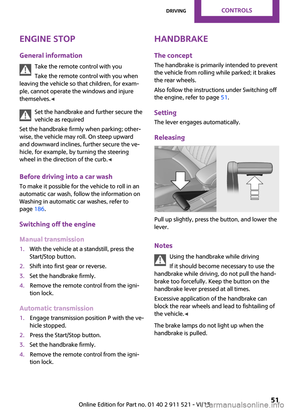
Releasing
Pull up slightly, press the button, and lower the
lever.
Notes Using the handbrake while driving
If it should become necessary to use the
handbrake while driving, do not pull the hand‐
brake too forcefully. Keep the button on the
handbrake lever pressed at all times.
Excessive application of the handbrake can
block the rear wheels and lead to fishtailing of
the vehicle. ◀
The brake lamps do not light up when the
handbrake is pulled.
Seite 51DrivingControls51
Online Edition for Part no. 01 40 2 911 521 - VI/13
Page 76 of 218
Do not initialize the system when driving with
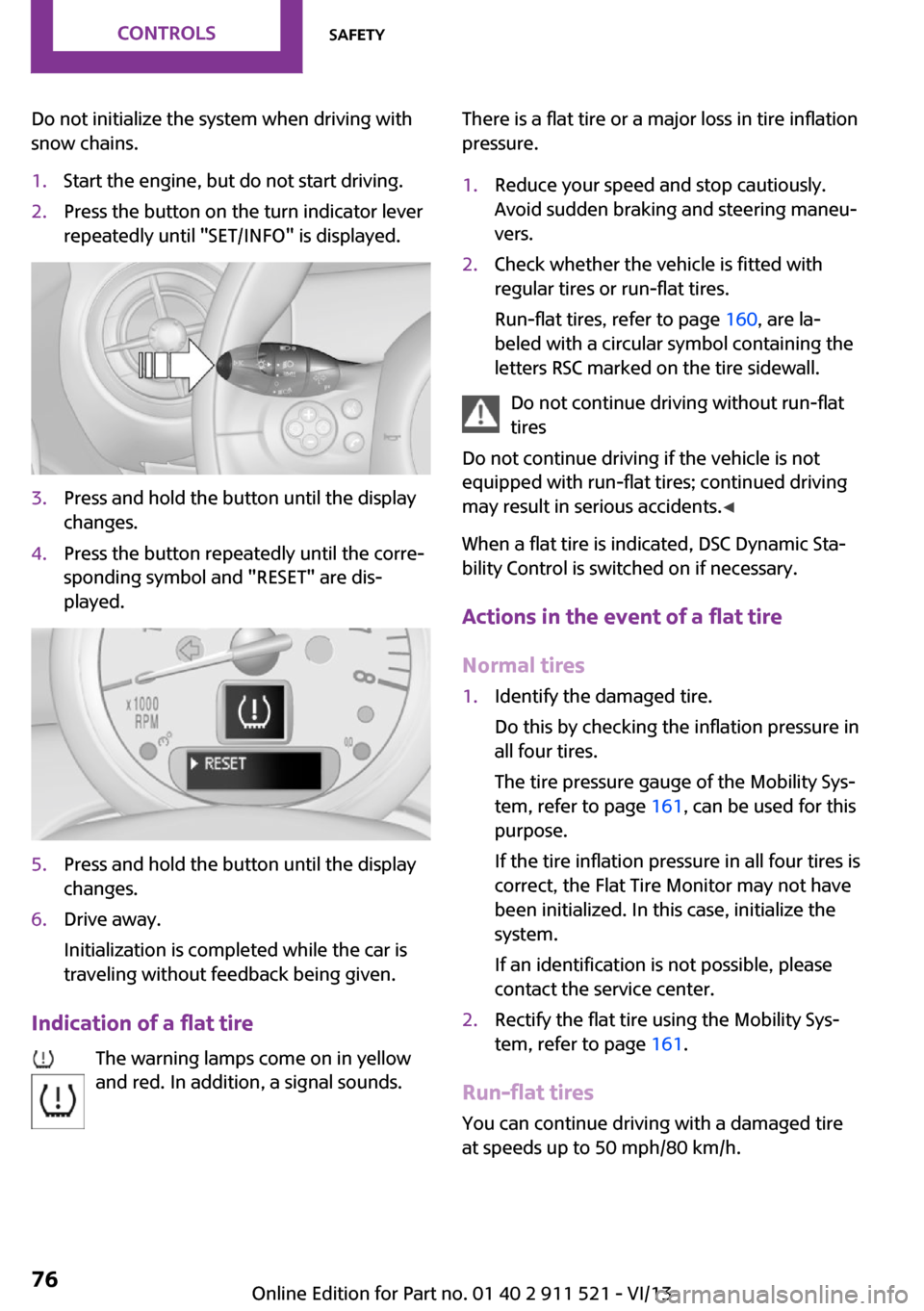
snow chains.1.Start the engine, but do not start driving.2.Press the button on the turn indicator lever
repeatedly until "SET/INFO" is displayed.3.Press and hold the button until the display
changes.4.Press the button repeatedly until the corre‐
sponding symbol and "RESET" are dis‐
played.5.Press and hold the button until the display
changes.6.Drive away.
Initialization is completed while the car is
traveling without feedback being given.
Indication of a flat tire
The warning lamps come on in yellow
and red. In addition, a signal sounds.
There is a flat tire or a major loss in tire inflation
pressure.1.Reduce your speed and stop cautiously.
Avoid sudden braking and steering maneu‐
vers.2.Check whether the vehicle is fitted with
regular tires or run-flat tires.
Run-flat tires, refer to page 160, are la‐
beled with a circular symbol containing the
letters RSC marked on the tire sidewall.
Do not continue driving without run-flat
tires
Do not continue driving if the vehicle is not
equipped with run-flat tires; continued driving
may result in serious accidents. ◀
When a flat tire is indicated, DSC Dynamic Sta‐
bility Control is switched on if necessary.
Actions in the event of a flat tire
Normal tires
1.Identify the damaged tire.
Do this by checking the inflation pressure in
all four tires.
The tire pressure gauge of the Mobility Sys‐
tem, refer to page 161, can be used for this
purpose.
If the tire inflation pressure in all four tires is
correct, the Flat Tire Monitor may not have
been initialized. In this case, initialize the
system.
If an identification is not possible, please
contact the service center.2.Rectify the flat tire using the Mobility Sys‐
tem, refer to page 161.
Run-flat tires
You can continue driving with a damaged tire
at speeds up to 50 mph/80 km/h.
Seite 76ControlsSafety76
Online Edition for Part no. 01 40 2 911 521 - VI/13
Page 78 of 218
▷When the TPM is disturbed by other sys‐
tems or devices with the same radio fre‐
quency.
Resetting the system
Reset the system after each correction of the
tire inflation pressure and after every tire or
wheel change.
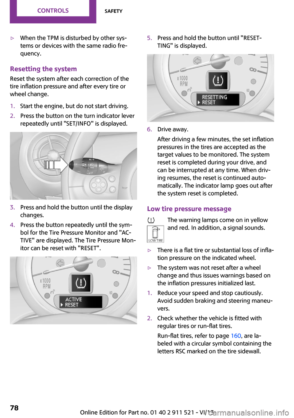
1.Start the engine, but do not start driving.2.Press the button on the turn indicator lever
repeatedly until "SET/INFO" is displayed.3.Press and hold the button until the display
changes.4.Press the button repeatedly until the sym‐
bol for the Tire Pressure Monitor and "AC‐
TIVE" are displayed. The Tire Pressure Mon‐
itor can be reset with "RESET".5.Press and hold the button until "RESET‐
TING" is displayed.6.Drive away.
After driving a few minutes, the set inflation
pressures in the tires are accepted as the
target values to be monitored. The system
reset is completed during your drive, and
can be interrupted at any time. When driv‐
ing resumes, the reset is continued auto‐
matically. The indicator lamp goes out after
the system reset is completed.
Low tire pressure message
The warning lamps come on in yellow
and red. In addition, a signal sounds.
▷There is a flat tire or substantial loss of infla‐
tion pressure on the indicated wheel.▷The system was not reset after a wheel
change and thus issues warnings based on
the inflation pressures initialized last.1.Reduce your speed and stop cautiously.
Avoid sudden braking and steering maneu‐
vers.2.Check whether the vehicle is fitted with
regular tires or run-flat tires.
Run-flat tires, refer to page 160, are la‐
beled with a circular symbol containing the
letters RSC marked on the tire sidewall.Seite 78ControlsSafety78
Online Edition for Part no. 01 40 2 911 521 - VI/13
Page 191 of 218
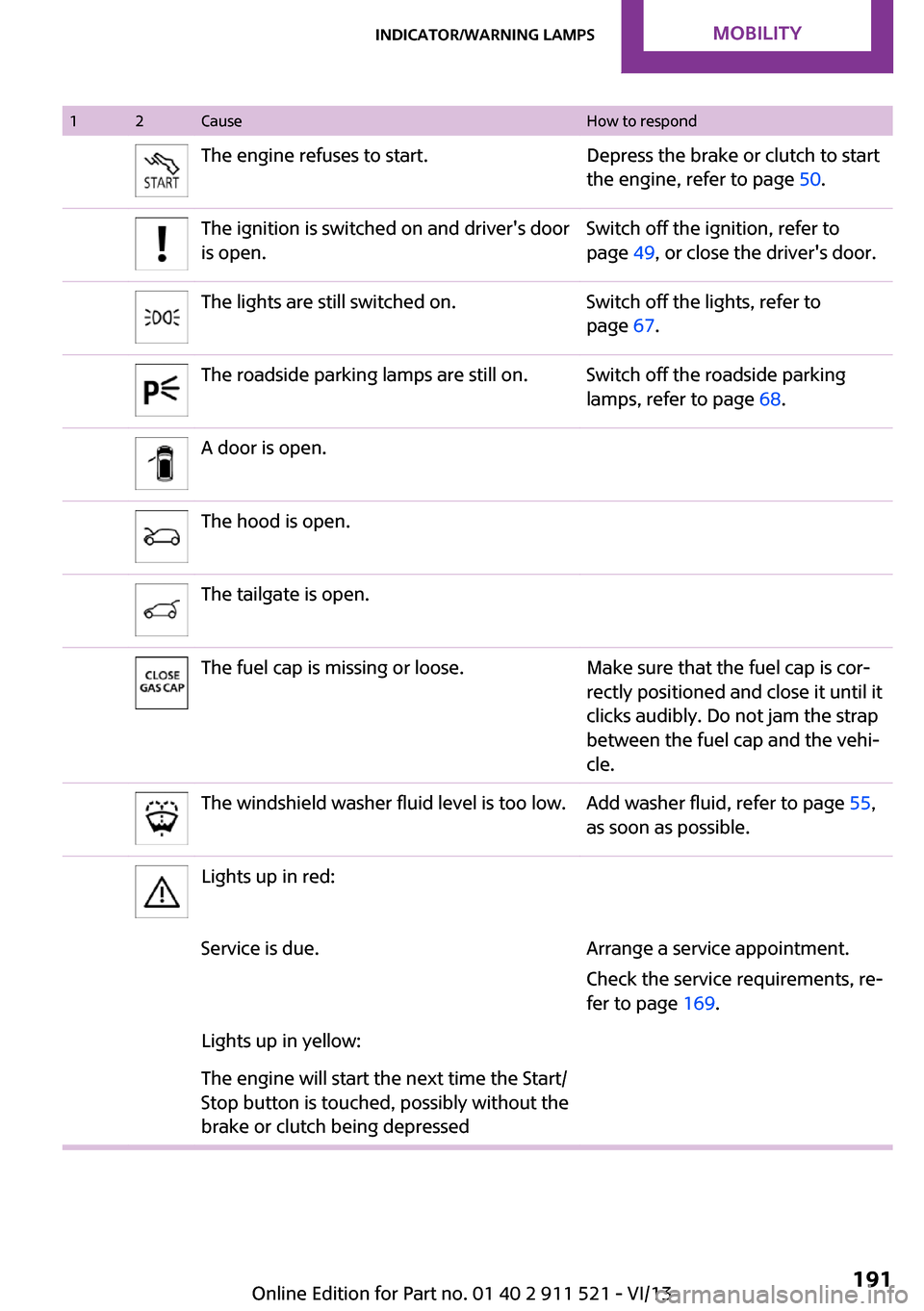
12CauseHow to respondThe engine refuses to start.Depress the brake or clutch to start
the engine, refer to page 50.The ignition is switched on and driver's door
is open.Switch off the ignition, refer to
page 49, or close the driver's door.The lights are still switched on.Switch off the lights, refer to
page 67.The roadside parking lamps are still on.Switch off the roadside parking
lamps, refer to page 68.A door is open.The hood is open.The tailgate is open.The fuel cap is missing or loose.Make sure that the fuel cap is cor‐
rectly positioned and close it until it
clicks audibly. Do not jam the strap
between the fuel cap and the vehi‐
cle.The windshield washer fluid level is too low.Add washer fluid, refer to page 55,
as soon as possible.Lights up in red:Service is due.Arrange a service appointment.
Check the service requirements, re‐
fer to page 169.Lights up in yellow:The engine will start the next time the Start/
Stop button is touched, possibly without the
brake or clutch being depressedSeite 191Indicator/warning lampsMobility191
Online Edition for Part no. 01 40 2 911 521 - VI/13
Page 209 of 218
Breakdown assistance, Road‐side Assistance 180
Breaking in 110
Buckle tongue, rear– Height adjustment 39
Button for starting the engine,
refer to Start/Stop button 49
C
California Proposition 65 Warning 7
Car battery, refer to Vehicle battery 178
Car care products 187
Care, displays 189
Care, vehicle 187
Cargo area
– Comfort Access 30– Flat loading floor 99– Multi-function hook 101– Opening from the out‐
side 28– Partition net 100
Cargo area, enlarging
– Cargo cover 98
Cargo area lamp, refer to Inte‐
rior lamps 70
Cargo area tailgate, refer to Tailgate 28
Car horn, refer to Horn 14
Carpet, care 189
Car phone, refer to Tele‐ phone 136
Car wash 186
CBC, Cornering Brake Con‐ trol 81
CBS Condition Based Serv‐ ice 169
CD/DVD drives, care 189
Center armrest 103
Center console, refer to Around the center con‐
sole 17
Center rail 104
Center rail, refer to Storage compartments 104
Central locking– Comfort Access 30– From the inside 27– From the outside 24
Central locking system
– Concept 23– From the outside 23
Changes, technical, refer to
Safety 7
Changing wheels/tires 159
Check Control 65
Children, transporting 44
Child restraint fixing system
LATCH 45
Child restraint fixing sys‐ tems 44
Child restraint fixing systems, mounting 44
Child seat, mounting 44
Child seats, refer to Transport‐ ing children safely 44
Chrome parts, care 189
Circulation of air, refer to Re‐ circulated air mode 88, 90
Cleaning, displays 189
Cleaning, refer to Care 186
Climate 87
Climate mode
– Ventilation 91
Clock 59
Clock
– 12h/24h format 62
Closing
– From the inside 27– From the outside 24
Clutch, breaking in 110
Cockpit 14
Cold start, refer to Starting the engine 50
Combination instrument, refer to Displays 16
Combination switch, refer to Turn signal/high beams/
headlamp flasher 52
Combination switch, refer to Washer/wiper system 53
Comfort Access– In the car wash 31– Replacing the battery 32
Comfort area, refer to Around
the center console 17
Compartment for remote con‐ trol, refer to Ignition lock 49
Compass, digital 94
Computer 60
Computer, displaying informa‐ tion 60
Condition Based Service CBS 169
Confirmation signals for vehi‐ cle locking/unlocking 25
Consumption, refer to Aver‐ age fuel consumption 61
Control Display, care 189
Controls and displays 14
Control systems, driving stabil‐ ity 81
Convenient operation
– Windows 25
Coolant temperature 60
Cooling function, switching on and off 91
Cooling, maximum 90
Cornering Brake Control, CBC 81
Corrosion on brake discs 112
Cradle for telephone or mobile phone, refer to Snap-in
adapter 143
Cruise control 84
Cupholders 96
Current fuel consumption 61
Curve lights, refer to Adaptive Light Control 69
Cylinders, number of, refer to Engine data 204
D
Dashboard lighting, refer to Instrument lighting 70
Dashboard, refer to Cock‐ pit 14
Seite 209Everything from A to ZReference209
Online Edition for Part no. 01 40 2 911 521 - VI/13
Page 210 of 218
Dashboard, refer to Dis‐plays 16
Data, technical 204
Date– Display format 62– Setting 63
Daytime running lights 68
Decorative trim, care 189
Defogging windows 88
Defroster
– Rear window 88, 91
Defrosting windows 88
Defrost setting, refer to De‐ frosting windows 88
Digital compass 94
Dip stick, engine oil 166
Directional indicators, refer to Turn signals 52
Displacement, refer to Engine data 204
Display lighting, refer to In‐ strument lighting 70
Displays 16
Displays and controls 14
Displays, care 189
Displays, cleaning 189
Displays, refer to Instrument cluster 16
Disposal
– Remote control battery 32
Distance warning, refer to
Park Distance Control
PDC 85
Door key, refer to Remote control with integrated
key 22
Door lock 26
Door lock, confirmation sig‐ nals 25
Doors, manual operation 27
Doors, unlocking and locking
– Confirmation signals 25– From the inside 27– From the outside 24
DOT Quality Grades 156
Drive-off assistant, refer to Hill drive-off assistant 83
Driving notes, breaking
in 110
Driving off on hills, refer to Hill drive-off assistant 83
Driving on poor roads 113
Driving stability control sys‐ tems 81
Driving tips, refer to Driving notes 110
Dry air, refer to Cooling func‐ tion 91
DSC Dynamic Stability Con‐ trol 81
DTC Dynamic Traction Con‐ trol 82
Dynamic Stability Control DSC 81
Dynamic Traction Control DTC 82
E Electrical malfunction– Door lock 27– Fuel filler flap 148
Electronic brake-force distri‐
bution 81
Electronic Stability Program ESP, refer to Dynamic Stabil‐
ity Control DSC 81
Emergency activation
– Automatic transmission, re‐
fer to Overriding selector
lever lock 58
Emergency operation, fuel
filler flap, unlocking man‐
ually 148
Emergency operation, refer to
Manual operation
– Door lock 27
Energy, saving, refer to Saving
fuel 118
Engine, breaking in 110
Engine compartment 164
Engine oil, adding 166
Engine oil, additives, refer to Approved engine oils 167
Engine oil, alternative oil
types 167
Engine oil change intervals, refer to Service require‐
ments 64
Engine oil, dip stick 166
Engine oil, filling capacity 207
Engine oil, MINI maintenance system 169
Engine oil types, alterna‐ tive 167
Engine oil types, ap‐ proved 167
Engine, overheating, refer to Coolant temperature 60
Engine power, refer to Engine data 204
Engine, RPM 204
Engine start, assistance 180
Engine, starting 50
Engine, starting– Comfort Access 30
Engine, starting, Start/Stop
button 49
Engine, stopping, Start/Stop button 49
Engine, switching off 51
Equipment, interior 92
ESP Electronic Stability Pro‐ gram, refer to Dynamic Sta‐
bility Control DSC 81
Exchanging wheels/tires 159
Exterior mirrors 42
Exterior mirrors, adjusting 42
Exterior mirrors, folding in and out 42
Exterior sensors, care 189
External temperature dis‐ play 59
External temperature display
– Changing the units 62– On the computer 62
External temperature warn‐
ing 59
Externel temperature dis‐ play 59
Seite 210ReferenceEverything from A to Z210
Online Edition for Part no. 01 40 2 911 521 - VI/13