change time MINI Paceman 2014 User Guide
[x] Cancel search | Manufacturer: MINI, Model Year: 2014, Model line: Paceman, Model: MINI Paceman 2014Pages: 218, PDF Size: 5.5 MB
Page 78 of 218
▷When the TPM is disturbed by other sys‐
tems or devices with the same radio fre‐
quency.
Resetting the system
Reset the system after each correction of the
tire inflation pressure and after every tire or
wheel change.
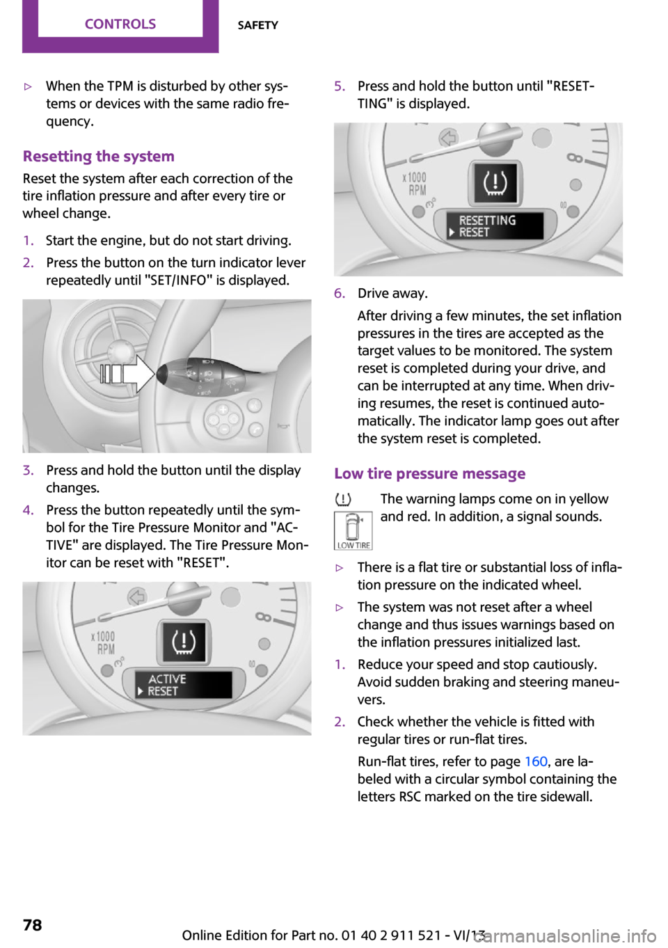
1.Start the engine, but do not start driving.2.Press the button on the turn indicator lever
repeatedly until "SET/INFO" is displayed.3.Press and hold the button until the display
changes.4.Press the button repeatedly until the sym‐
bol for the Tire Pressure Monitor and "AC‐
TIVE" are displayed. The Tire Pressure Mon‐
itor can be reset with "RESET".5.Press and hold the button until "RESET‐
TING" is displayed.6.Drive away.
After driving a few minutes, the set inflation
pressures in the tires are accepted as the
target values to be monitored. The system
reset is completed during your drive, and
can be interrupted at any time. When driv‐
ing resumes, the reset is continued auto‐
matically. The indicator lamp goes out after
the system reset is completed.
Low tire pressure message
The warning lamps come on in yellow
and red. In addition, a signal sounds.
▷There is a flat tire or substantial loss of infla‐
tion pressure on the indicated wheel.▷The system was not reset after a wheel
change and thus issues warnings based on
the inflation pressures initialized last.1.Reduce your speed and stop cautiously.
Avoid sudden braking and steering maneu‐
vers.2.Check whether the vehicle is fitted with
regular tires or run-flat tires.
Run-flat tires, refer to page 160, are la‐
beled with a circular symbol containing the
letters RSC marked on the tire sidewall.Seite 78ControlsSafety78
Online Edition for Part no. 01 40 2 911 521 - VI/13
Page 81 of 218
Driving stability control systemsVehicle equipment
This chapter describes all series equipment as
well as country-specific and special equipment
offered for this model series.Therefore, it also
describes equipment that may not be found in
your vehicle, for instance due to the selected
special equipment or the country version. This
also applies to safety-related functions and sys‐
tems.
Antilock Brake System
ABS
ABS prevents locking of the wheels duringbraking.
Steerability is maintained even during full brak‐
ing. This increases active driving safety.
ABS is operational every time you start the en‐
gine.
Electronic brake-force distribution EBVThe system controls the brake pressure in the
rear wheels to ensure stable braking behavior.
CBC Cornering Brake Control
When braking in curves or during a lane
change, driving stability and steering response
are improved further.
Brake assistant When the brakes are applied rapidly, this sys‐
tem automatically produces the maximum
braking force boost. In this way, the system
helps keep the braking distance as short as
possible. This system utilizes all of the benefits
provided by ABS.Do not reduce the pressure on the brake pedal
for the duration of full braking.
Dynamic Stability Con‐
trol DSC
The concept
DSC prevents traction loss in the driving wheels
when driving away and accelerating.
DSC also recognizes unstable vehicle condi‐
tions, such as fishtailing or nose-diving. Subject
to physical limits, DSC helps to keep the vehicle
on a steady course by reducing engine speed
and by applying brakes to the individual
wheels.
DSC is operational every time you start the en‐
gine.
Adjust your driving style to the situation
An appropriate driving style is always the
responsibility of the driver.
The laws of physics cannot be repealed, even
with DSC.
Do not reduce the additional safety margin
with a risky driving style, as otherwise there is a
risk of an accident. ◀
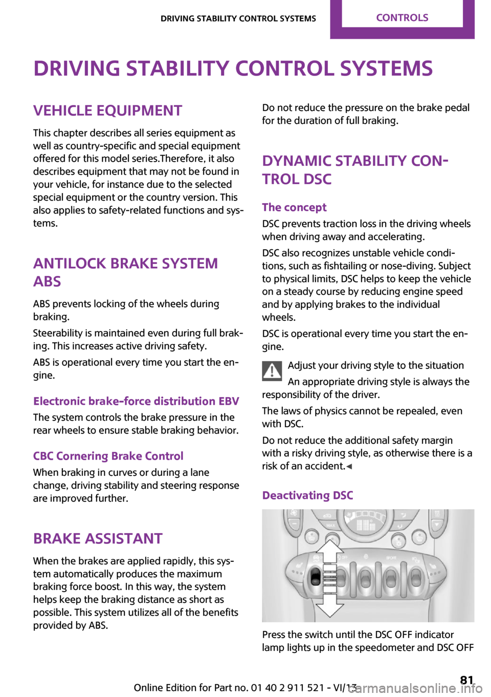
Deactivating DSC
Press the switch until the DSC OFF indicator
lamp lights up in the speedometer and DSC OFF
Seite 81Driving stability control systemsControls81
Online Edition for Part no. 01 40 2 911 521 - VI/13
Page 93 of 218
3.Hold the hand-held transmitter of the sys‐
tem to be operated a distance of approx. 1
to 3 in/2.5 to 8 cm away from the buttons
on the interior rearview mirror. The re‐
quired distance depends on the particular
hand-held transmitter.4.Press the button of the desired function on
the hand-held transmitter and the button
being programmed on the interior rearview
mirror simultaneously and hold. The LED on
the interior rearview mirror flashes slowly at
first.5.When the LED flashes more rapidly, release
both buttons. Rapid flashing indicates that
the button on the interior rearview mirror
has been programmed.
If the LED does not flash faster after 60 sec‐
onds, change the distance between the in‐
terior rearview mirror and the hand-held
transmitter and repeat the step. Multiple
trials at different distances may be neces‐
sary. Wait at least 15 seconds between tri‐
als.6.To program additional functions on other
buttons, repeat steps 3 to 5.
The systems can be operated with the buttons
on the interior rearview mirror.
Special characteristics of alternating-
code radio systems
If the system cannot be operated after re‐
peated programming, check whether the sys‐
tem to be operated uses an alternating-code
system.
Read the operating instructions of the system
or press and hold the programmed button on
the interior rearview mirror. If the LED on the
interior rearview mirror flashes rapidly at first
and then lights up continuously for 2 seconds,
the system is equipped with an alternating-
code system. This flashing LED pattern repeats
itself for approx. 20 seconds.
In systems with an alternating-code system, the
universal garage door opener and the system
must be additionally synchronized.
Please obtain additional information on syn‐
chronization in the operating instructions of the
system being set up.
The systems will be easier to synchronize with
the aid of a second person.
Synchronization:1.Park the vehicle within range of the re‐
mote-controlled system.2.Program the corresponding button on the
interior rearview mirror as described.3.Identify and press the synchronization but‐
ton on the system being set up. You have
approx. 30 seconds for the next step.4.Press and hold the button on the interior
rearview mirror for approx. 3 seconds and
then release it. Repeat this step up to three
times if necessary to complete the synchro‐
nization procedure. When synchronization
is completed, the programmed function is
executed.
Reprogramming individual buttons
1.Switch on the ignition.2.Hold the hand-held transmitter at a dis‐
tance of approx. 1 to 3 in/2.5 to 8 cm from
the memory buttons.
The required distance depends on the par‐
ticular hand-held transmitter.3.Press the memory button of the universal
garage door opener.4.If the LED flashes slowly after approx.
20 seconds, press the transmit button on
the hand-held transmitter.5.Release both buttons when the LED flashes
rapidly.
If the LED does not flash rapidly after ap‐
prox. 60 seconds, change the distance and
repeat the step.Seite 93Interior equipmentControls93
Online Edition for Part no. 01 40 2 911 521 - VI/13
Page 94 of 218
Canada: if the LED does not flash rapidly af‐
ter approx. 60 seconds, change the dis‐
tance and repeat the step. If programming
was aborted by the hand-held transmitter,
hold down the memory button and press
and release the button on the hand-held
transmitter several times for 2 seconds.
Controls
Prior to operation
Before operating a unit with the Universal
Garage Door Opener, ensure that there are no
people, animals, or objects in the range of
movement of the system; otherwise, there is a
risk of injury or damage.
Also follow the safety instructions of the hand-
held transmitter. ◀
The system, such as the garage door, can be
operated using the button on the interior rear‐
view mirror with the engine running or the igni‐
tion switched on. When you are within the re‐
ception range of the system, press and hold the
button until the function is initiated. The LED on
the interior rearview mirror lights up continu‐
ously while the radio signal is being transmit‐
ted.
Deleting stored functions
Press the right and left buttons on the interior
rearview mirror simultaneously for approx.
20 seconds until the LED flashes rapidly. All
stored functions are deleted. The functions can‐
not be deleted individually.
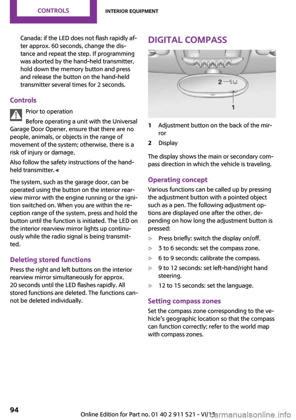
Digital compass1Adjustment button on the back of the mir‐
ror2Display
The display shows the main or secondary com‐
pass direction in which the vehicle is traveling.
Operating concept
Various functions can be called up by pressing
the adjustment button with a pointed object
such as a pen. The following adjustment op‐
tions are displayed one after the other, de‐
pending on how long the adjustment button is
pressed:
▷Press briefly: switch the display on/off.▷3 to 6 seconds: set the compass zone.▷6 to 9 seconds: calibrate the compass.▷9 to 12 seconds: set left-hand/right hand
steering.▷12 to 15 seconds: set the language.
Setting compass zones
Set the compass zone corresponding to the ve‐
hicle's geographic location so that the compass
can function correctly; refer to the world map
with compass zones.
Seite 94ControlsInterior equipment94
Online Edition for Part no. 01 40 2 911 521 - VI/13
Page 124 of 218
Adjusting the volumeTurn the left knob. The setting is stored for the
remote control currently in use.
When a call is placed using the hands-free sys‐
tem, the audio sources are muted.
Speed-dependent volume and volumes
of PDC signal tone and gong▷"PDC": volume of the PDC signal tone com‐
pared to the audio sources.▷"GONG": volume of the gong compared to
the audio sources.▷"S-VOL": speed-dependent volume control.
Set the audio sources to a high volume to be
able to adjust the volume of the signal tones
more easily.
1. Press the button.2. Select the symbol if necessary.3.Select the desired volume setting.4.Set the desired volume and press the right
knob.
Volume of external audio devices
An external audio device such as an MP3 player
can be connected via the AUX-IN port in the
center console and the audio tracks can be
played over the car's loudspeaker system.
The volume of the external audio device can be
adjusted to the car radio.
1. Press the button.2."AUX"3."Vol-AUX"4.Set the desired volume and press the right
knob.
Tone settings
▷"BASS": depth adjustment.▷"TREBLE": treble adjustment.▷"FADER": front/rear volume distribution.▷"BAL": left/right volume distribution.
The sound settings are set globally for all audio
sources.
Setting the treble, bass, and volume distribution
1. Press the button.2.Highlight the desired tone setting and press
the right knob.3.Create the desired setting and press the
right knob.
Resetting the tone settings
The tone settings are reset to medium values.
1. Press the button.2."RESET"
Time
Setting the time, date, and time format
1.Switch on the radio ready state or the igni‐
tion.2. Press the button.3."CONFIG"4."TIME"5.Select the desired category.6.Create the settings and press the right
knob.
Setting the units of measure of the
computer and the language
1.Switch on the radio ready state or the igni‐
tion.2. Press the button.3."CONFIG"4.▷"DIST": change the unit of measure for
the range.Seite 124EntertainmentRadio MINI Boost CD124
Online Edition for Part no. 01 40 2 911 521 - VI/13
Page 125 of 218
▷"LANG": select the language of the dis‐
play texts.▷"CONSMP": change the unit of measure
for the average fuel consumption.▷"TEMP": change the unit of measure for
the external temperature.5.Highlight the desired menu item and press
the button.6.Create the desired setting.
Computer
The following vehicle information can be call up
via the computer:
▷Average fuel consumption▷Average speed▷Range
Displaying information
1.Switch on the radio ready state or the igni‐
tion.2. Press the button.3."COMP"
Average fuel consumption
The average fuel consumption is calculated for
the time during which the engine is running.
To start calculation of the average fuel con‐
sumption:
1."CONSMP"2."RESET"
The previous display is set to zero and the sys‐
tem begins recalculating the average fuel con‐
sumption.
Average speed
The average speed is calculated for the time
during which the engine is running.
To start calculation of the average speed:
1."SPEED"2."RESET"
Estimated range
"RANGE"
The display shows the estimated distance that
can be still be driven on the remaining fuel,
taking into consideration the driving style over
the last 18 miles/30 km.
Radio
Listening to the radio
The radio is designed for reception in the FM
and AM wavebands.
1.Switch on the radio, refer to page 123.2. Press this button if necessary.3."TUNER"4."FM" or"AM"
Press the corresponding button repeatedly
until the desired waveband is displayed.▷FM: FM1, FM2, FMA▷AM: AM, AMA
Selecting a station
The setting is stored for the remote control cur‐
rently in use.
Next station
Press the button.
The next station with reception is selected.
Selecting the station manually by
frequency
1. Press the button.2.▷Press the respective function button to
set the desired frequency.▷Turn the right knob until the desired
frequency is set.Seite 125Radio MINI Boost CDEntertainment125
Online Edition for Part no. 01 40 2 911 521 - VI/13
Page 133 of 218
Random playback
"RND"
To end random playback: "RND"
Selecting a track
Depending on the connected device, the track
can be selected via the following category:▷"LIST": playback lists.▷"GEN": musical genre.▷"ART": artist.▷"ALB": album.1.Select the desired category.2.If necessary, select the desired directory us‐
ing the right knob.▷ : press the right knob to open a di‐
rectory.▷ : press the right knob to close a di‐
rectory.3.Select other directories if you wish.4.Highlight the desired track and press the
right knob.
You can scroll through the directories during
playback.
To change to the current track:
"CURR"
Displaying information on the track
Any information stored on the currently se‐
lected track can be displayed.
"TRACK"
Adjusting the volumeThe volume of the sound output is dependent
on the audio device. If this volume differs
markedly from the volume of the other audio
sources, it is advisable to adjust the volumes.
1."LEV"2.Turn the right knob until the desired vol‐
ume is set and press the knob.Notes
Do not expose the audio device to extreme en‐
vironmental conditions, such as very high tem‐
peratures; refer to the audio device operating
instructions.
Depending on the configuration of the audio
files, e.g., bit rates greater than 256 kbit/s, the
files may not play back correctly in each case.
Information on connection▷It is only possible to connect one iPod/
iPhone to the vehicle at a time.▷Playback from the iPod/iPhone is only pos‐
sible via the USB audio interface if a snap-in
adapter is not used.▷The connected audio device is supplied
with a max. power of 500 mA if supported
by the device. Therefore, do not addition‐
ally connect the device to a socket in the
vehicle; otherwise, playback may be com‐
promised.▷Do not use force when plugging the con‐
nector into the USB interface.▷Do not connect devices such as fans or
lamps to the USB audio interface.▷Do not connect USB hard drives.▷Do not use the USB audio interface to re‐
charge external devices.Seite 133Radio MINI Boost CDEntertainment133
Online Edition for Part no. 01 40 2 911 521 - VI/13
Page 172 of 218
Lamp and bulb replace‐
ment
Notes
Lamps and bulbs Lamps and bulbs make an essential contribu‐
tion to vehicle safety. Therefore, exercise cau‐
tion when handling lamps and bulbs.
The manufacturer of the vehicle recommends
that you entrust corresponding procedures to
the service center if you are unfamiliar with
them or they are not described here.
You can obtain a selection of replacement
bulbs at the service center.
Danger of burns
Only change bulbs when they are cool;
otherwise, there is the danger of getting
burned. ◀
Working on the lighting system
When working on the lighting system,
you should always switch off the lights affected
to prevent short circuits.
To avoid possible injury or equipment damage
when replacing bulbs, observe any instructions
provided by the bulb manufacturer. ◀
Do not touch the bulbs
Do not touch the glass of new bulbs with
your bare hands, as even minute amounts of
contamination will burn into the bulb's surface
and reduce its service life.
Use a clean tissue, cloth or something similar,
or hold the bulb by its base. ◀
Caring for the headlamps, refer to page 187.
For bulb replacement that is not described
here, please contact the service center or a
workshop that works according to the repair
procedures of the manufacturer with corre‐
spondingly trained personnel.For checking and adjusting headlamp aim,
please contact your MINI dealer.
Light-emitting diodes LEDs Light-emitting diodes installed behind translu‐
cent lenses serve as the light source for many
of the controls and displays in the vehicle.
These light-emitting diodes, which operate us‐
ing a concept similar to that applied in conven‐
tional lasers, are officially designated as Class 1
light-emitting diodes.
Do not remove the covers
Do not remove the covers, and never
stare into the unfiltered light for several hours;
otherwise, irritation of the retina could result. ◀
Headlamp glass
Condensation can form on the inside of the
headlamps in cool or humid weather. When the
light is switched on, the condensation evapo‐ rates after a short time. The headlamps do notneed to be changed.
If the condensation in the headlamps does not
evaporate after trips with the lights switched
on, and the amount of moisture in the head‐
lamps increases, for example if water droplets
form, have them checked by your service cen‐
ter.
Bi-xenon headlamps These bulbs have a very long life and the likeli‐
hood of failure is very low, provided that they
are not switched on and off excessively. If a
bulb should nevertheless fail, you can continue
driving cautiously with the front fog lamps, pro‐
vided this is permitted by local laws.
Do not perform work/bulb replacement
on xenon headlamps
Have any work on the xenon lighting system,
including bulb replacement, performed only by
a service center.Seite 172MobilityReplacing components172
Online Edition for Part no. 01 40 2 911 521 - VI/13
Page 210 of 218
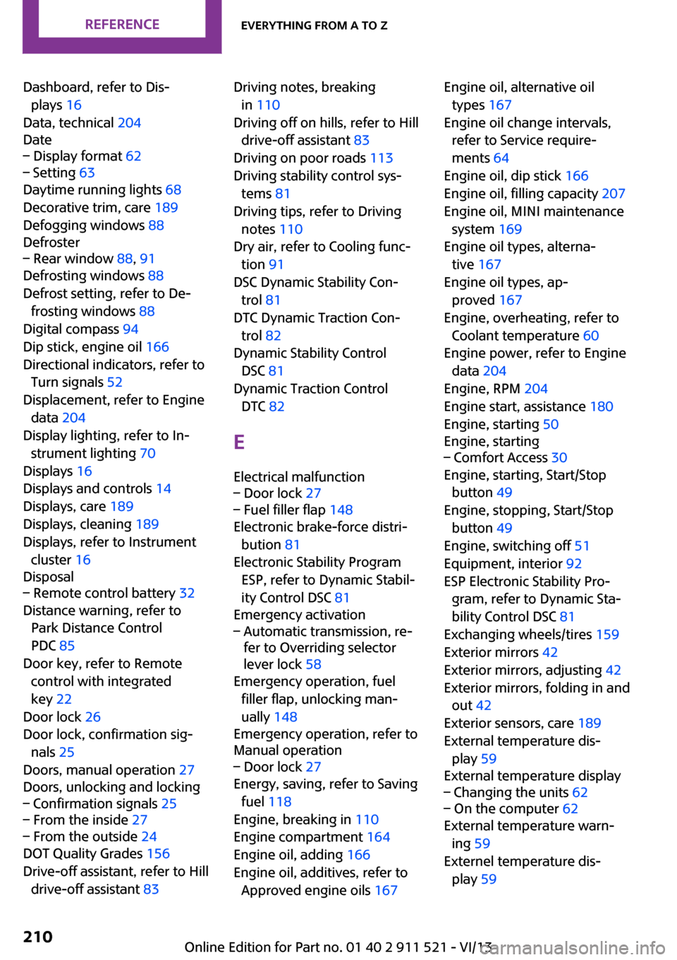
Dashboard, refer to Dis‐plays 16
Data, technical 204
Date– Display format 62– Setting 63
Daytime running lights 68
Decorative trim, care 189
Defogging windows 88
Defroster
– Rear window 88, 91
Defrosting windows 88
Defrost setting, refer to De‐ frosting windows 88
Digital compass 94
Dip stick, engine oil 166
Directional indicators, refer to Turn signals 52
Displacement, refer to Engine data 204
Display lighting, refer to In‐ strument lighting 70
Displays 16
Displays and controls 14
Displays, care 189
Displays, cleaning 189
Displays, refer to Instrument cluster 16
Disposal
– Remote control battery 32
Distance warning, refer to
Park Distance Control
PDC 85
Door key, refer to Remote control with integrated
key 22
Door lock 26
Door lock, confirmation sig‐ nals 25
Doors, manual operation 27
Doors, unlocking and locking
– Confirmation signals 25– From the inside 27– From the outside 24
DOT Quality Grades 156
Drive-off assistant, refer to Hill drive-off assistant 83
Driving notes, breaking
in 110
Driving off on hills, refer to Hill drive-off assistant 83
Driving on poor roads 113
Driving stability control sys‐ tems 81
Driving tips, refer to Driving notes 110
Dry air, refer to Cooling func‐ tion 91
DSC Dynamic Stability Con‐ trol 81
DTC Dynamic Traction Con‐ trol 82
Dynamic Stability Control DSC 81
Dynamic Traction Control DTC 82
E Electrical malfunction– Door lock 27– Fuel filler flap 148
Electronic brake-force distri‐
bution 81
Electronic Stability Program ESP, refer to Dynamic Stabil‐
ity Control DSC 81
Emergency activation
– Automatic transmission, re‐
fer to Overriding selector
lever lock 58
Emergency operation, fuel
filler flap, unlocking man‐
ually 148
Emergency operation, refer to
Manual operation
– Door lock 27
Energy, saving, refer to Saving
fuel 118
Engine, breaking in 110
Engine compartment 164
Engine oil, adding 166
Engine oil, additives, refer to Approved engine oils 167
Engine oil, alternative oil
types 167
Engine oil change intervals, refer to Service require‐
ments 64
Engine oil, dip stick 166
Engine oil, filling capacity 207
Engine oil, MINI maintenance system 169
Engine oil types, alterna‐ tive 167
Engine oil types, ap‐ proved 167
Engine, overheating, refer to Coolant temperature 60
Engine power, refer to Engine data 204
Engine, RPM 204
Engine start, assistance 180
Engine, starting 50
Engine, starting– Comfort Access 30
Engine, starting, Start/Stop
button 49
Engine, stopping, Start/Stop button 49
Engine, switching off 51
Equipment, interior 92
ESP Electronic Stability Pro‐ gram, refer to Dynamic Sta‐
bility Control DSC 81
Exchanging wheels/tires 159
Exterior mirrors 42
Exterior mirrors, adjusting 42
Exterior mirrors, folding in and out 42
Exterior sensors, care 189
External temperature dis‐ play 59
External temperature display
– Changing the units 62– On the computer 62
External temperature warn‐
ing 59
Externel temperature dis‐ play 59
Seite 210ReferenceEverything from A to Z210
Online Edition for Part no. 01 40 2 911 521 - VI/13
Page 215 of 218
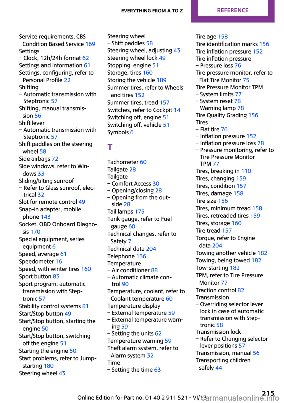
Service requirements, CBSCondition Based Service 169
Settings– Clock, 12h/24h format 62
Settings and information 61
Settings, configuring, refer to Personal Profile 22
Shifting
– Automatic transmission with
Steptronic 57
Shifting, manual transmis‐
sion 56
Shift lever
– Automatic transmission with
Steptronic 57
Shift paddles on the steering
wheel 58
Side airbags 72
Side windows, refer to Win‐ dows 33
Sliding/tilting sunroof
– Refer to Glass sunroof, elec‐
trical 32
Slot for remote control 49
Snap-in adapter, mobile phone 143
Socket, OBD Onboard Diagno‐ sis 170
Special equipment, series equipment 6
Speed, average 61
Speedometer 16
Speed, with winter tires 160
Sport button 83
Sport program, automatic transmission with Step‐
tronic 57
Stability control systems 81
Start/Stop button 49
Start/Stop button, starting the engine 50
Start/Stop button, switching off the engine 51
Starting the engine 50
Start problems, refer to Jump- starting 180
Steering wheel 43
Steering wheel– Shift paddles 58
Steering wheel, adjusting 43
Steering wheel lock 49
Stopping, engine 51
Storage, tires 160
Storing the vehicle 189
Summer tires, refer to Wheels and tires 152
Summer tires, tread 157
Switches, refer to Cockpit 14
Switching off, engine 51
Switching off, vehicle 51
Symbols 6
T Tachometer 60
Tailgate 28
Tailgate
– Comfort Access 30– Opening/closing 28– Opening from the out‐
side 28
Tail lamps 175
Tank gauge, refer to Fuel gauge 60
Technical changes, refer to Safety 7
Technical data 204
Telephone 136
Temperature
– Air conditioner 88– Automatic climate con‐
trol 90
Temperature, coolant, refer to
Coolant temperature 60
Temperature display
– External temperature 59– External temperature warn‐
ing 59– Setting the units 62
Temperature warning 59
Theft alarm system, refer to Alarm system 32
Time
– Setting the time 63Tire age 158
Tire identification marks 156
Tire inflation pressure 152
Tire inflation pressure– Pressure loss 76
Tire pressure monitor, refer to
Flat Tire Monitor 75
Tire Pressure Monitor TPM
– System limits 77– System reset 78– Warning lamp 78
Tire Quality Grading 156
Tires
– Flat tire 76– Inflation pressure 152– Inflation pressure loss 78– Pressure monitoring, refer to
Tire Pressure Monitor
TPM 77
Tires, breaking in 110
Tires, changing 159
Tires, condition 157
Tires, damage 158
Tire size 156
Tires, minimum tread 158
Tires, retreaded tires 159
Tires, storage 160
Tire tread 157
Torque, refer to Engine data 204
Towing another vehicle 182
Towing, being towed 182
Tow-starting 182
TPM, refer to Tire Pressure Monitor 77
Traction control 82
Transmission
– Overriding selector lever
lock in case of automatic
transmission with Step‐
tronic 58
Transmission lock
– Refer to Changing selector
lever positions 57
Transmission, manual 56
Transporting children safely 44
Seite 215Everything from A to ZReference215
Online Edition for Part no. 01 40 2 911 521 - VI/13