light MINI Paceman 2014 User Guide
[x] Cancel search | Manufacturer: MINI, Model Year: 2014, Model line: Paceman, Model: MINI Paceman 2014Pages: 218, PDF Size: 5.5 MB
Page 35 of 218
Danger of pinching even with pinch pro‐
tection
Even with the pinch protection system, check
that the window's closing path is clear; other‐
wise, the closing action may not stop in certain
situations, e.g., if thin objects are present. ◀
Do not use window accessories
Do not install any accessories in the range
of movement of the windows; otherwise, the
pinch protection system will be impaired. ◀
Closing without the pinch protection
system
Danger of pinching
Monitor the closing process and make
sure that the closing path of the window is
clear; otherwise, injuries may result. ◀
If there is an external danger or, for example, if
ice on the windows prevents a window from
closing normally, the window can be closed
manually.1.Pull the switch past the resistance point and
hold it there. Pinch protection is limited and
the window reopens slightly if the closing
force exceeds a certain value.2.Pull the switch past the resistance point
again within approx. 4 seconds and hold it
there.
The window closes without pinch protec‐
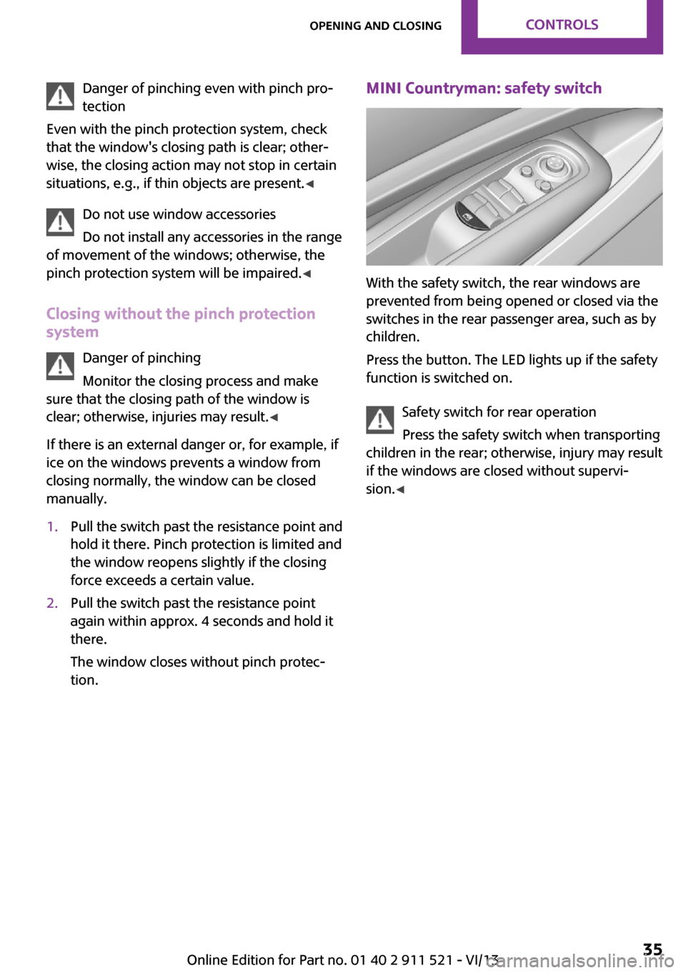
tion.MINI Countryman: safety switch
With the safety switch, the rear windows are
prevented from being opened or closed via the
switches in the rear passenger area, such as by
children.
Press the button. The LED lights up if the safety
function is switched on.
Safety switch for rear operation
Press the safety switch when transporting
children in the rear; otherwise, injury may result
if the windows are closed without supervi‐
sion. ◀
Seite 35Opening and closingControls35
Online Edition for Part no. 01 40 2 911 521 - VI/13
Page 36 of 218
AdjustingVehicle equipment
This chapter describes all series equipment as
well as country-specific and special equipment
offered for this model series.Therefore, it also
describes equipment that may not be found in
your vehicle, for instance due to the selected
special equipment or the country version. This
also applies to safety-related functions and sys‐
tems.
Sitting safely The ideal seating position can make a vital con‐
tribution to relaxed, fatigue-free driving.
The seating position plays an important role in
an accident in combination with:▷Safety belts, refer to page 38▷Head restraints, refer to page 41.▷Airbags, refer to page 72.
Seats
Note before adjusting Do not adjust the seat while driving
Never attempt to adjust the driver's seat
while driving. The seat could respond with un‐
expected movement and the ensuing loss of
vehicle control could lead to an accident. ◀
Do not incline the backrest too far to the
rear
Do not incline the backrest on the front passen‐
ger side too far to the rear during driving. Oth‐
erwise, there is the danger of sliding under the
safety belt in an accident. This would eliminate
the protection normally provided by the belt. ◀
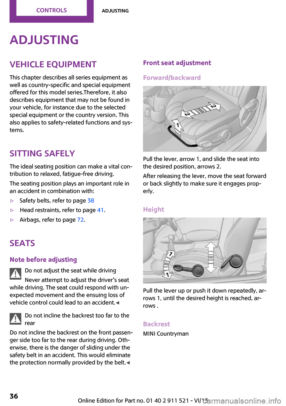
Front seat adjustment
Forward/backward
Pull the lever, arrow 1, and slide the seat into
the desired position, arrows 2.
After releasing the lever, move the seat forward
or back slightly to make sure it engages prop‐
erly.
Height
Pull the lever up or push it down repeatedly, ar‐
rows 1, until the desired height is reached, ar‐
rows .
Backrest MINI Countryman
Seite 36ControlsAdjusting36
Online Edition for Part no. 01 40 2 911 521 - VI/13
Page 37 of 218
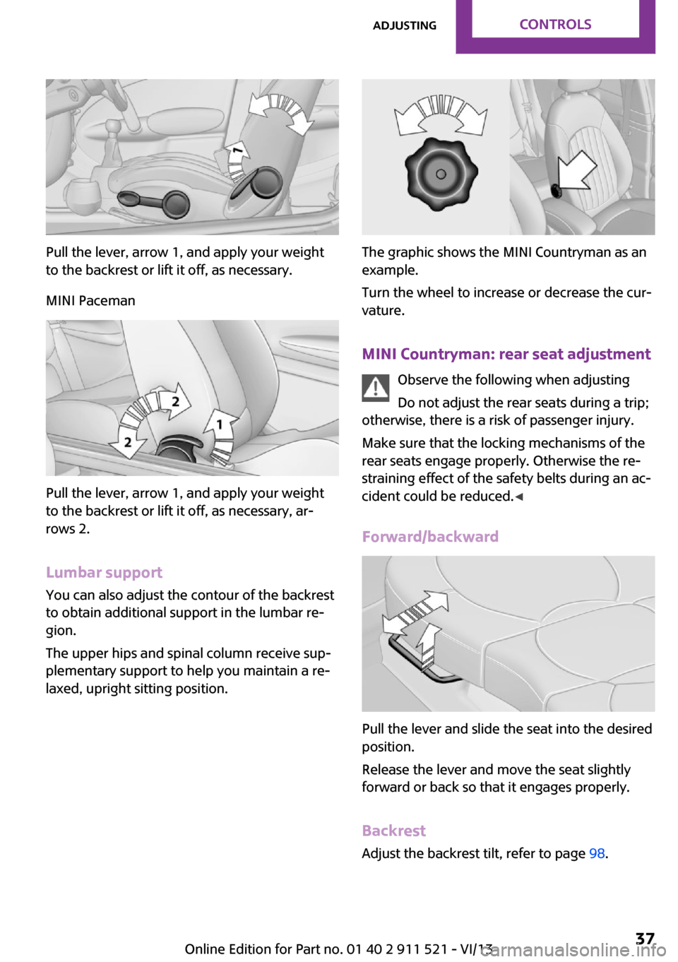
Pull the lever, arrow 1, and apply your weight
to the backrest or lift it off, as necessary.
MINI Paceman
Pull the lever, arrow 1, and apply your weight
to the backrest or lift it off, as necessary, ar‐
rows 2.
Lumbar support
You can also adjust the contour of the backrest
to obtain additional support in the lumbar re‐
gion.
The upper hips and spinal column receive sup‐
plementary support to help you maintain a re‐
laxed, upright sitting position.
The graphic shows the MINI Countryman as an
example.
Turn the wheel to increase or decrease the cur‐
vature.
MINI Countryman: rear seat adjustment Observe the following when adjusting
Do not adjust the rear seats during a trip;
otherwise, there is a risk of passenger injury.
Make sure that the locking mechanisms of the
rear seats engage properly. Otherwise the re‐
straining effect of the safety belts during an ac‐
cident could be reduced. ◀
Forward/backward
Pull the lever and slide the seat into the desired
position.
Release the lever and move the seat slightly
forward or back so that it engages properly.
Backrest Adjust the backrest tilt, refer to page 98.
Seite 37AdjustingControls37
Online Edition for Part no. 01 40 2 911 521 - VI/13
Page 41 of 218
Safety belt reminder for driver's seat
and front passenger seat
The indicator lamps light up and a sig‐
nal sounds. Check whether the safety
belt has been fastened correctly.
Damage to safety belts In the case of strain caused by accidents or
damage:
Have the safety belts, including the safety belt
tensioners, replaced and have the belt anchors
checked.
Checking and replacing safety belts
Have the work performed only by your
service center; otherwise, it cannot be ensured
that this safety feature will function properly. ◀
Head restraints Correctly set head restraintA correctly adjusted head restraint reduces the
risk of spinal injury in the event of an accident.
Adjusting the head restraint
Correctly adjust the head restraints of all
occupied seats; otherwise, there is an increased
risk of injury in an accident. ◀
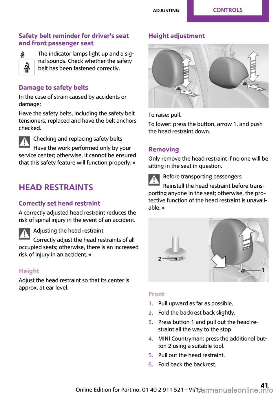
Height
Adjust the head restraint so that its center is
approx. at ear level.Height adjustment
To raise: pull.
To lower: press the button, arrow 1, and push
the head restraint down.
Removing
Only remove the head restraint if no one will be
sitting in the seat in question.
Before transporting passengers
Reinstall the head restraint before trans‐
porting anyone in the seat; otherwise, the pro‐
tective function of the head restraint is unavail‐
able. ◀
Front
1.Pull upward as far as possible.2.Fold the backrest back slightly.3.Press button 1 and pull out the head re‐
straint all the way to the stop.4.MINI Countryman: press the additional but‐
ton 2 using a suitable tool.5.Pull out the head restraint.6.Fold back the backrest.Seite 41AdjustingControls41
Online Edition for Part no. 01 40 2 911 521 - VI/13
Page 42 of 218
Rear1.Pull upward as far as possible.2.Fold the backrest forward slightly.3.Press button 1 and pull out the head re‐
straint all the way to the stop.4.Press the additional button 2 using a suita‐
ble tool.5.Pull out the head restraint completely.6.Fold back the rear seat backrest.
Mirrors
Exterior mirrors
General information
The mirror on the passenger side is more
curved than the driver's mirror.
Estimating distances correctly
Objects reflected in the mirror are closer
than they appear. Do not estimate the distance to the traffic behind you based on what you see
in the mirror, as this will increase your risk of an
accident. ◀
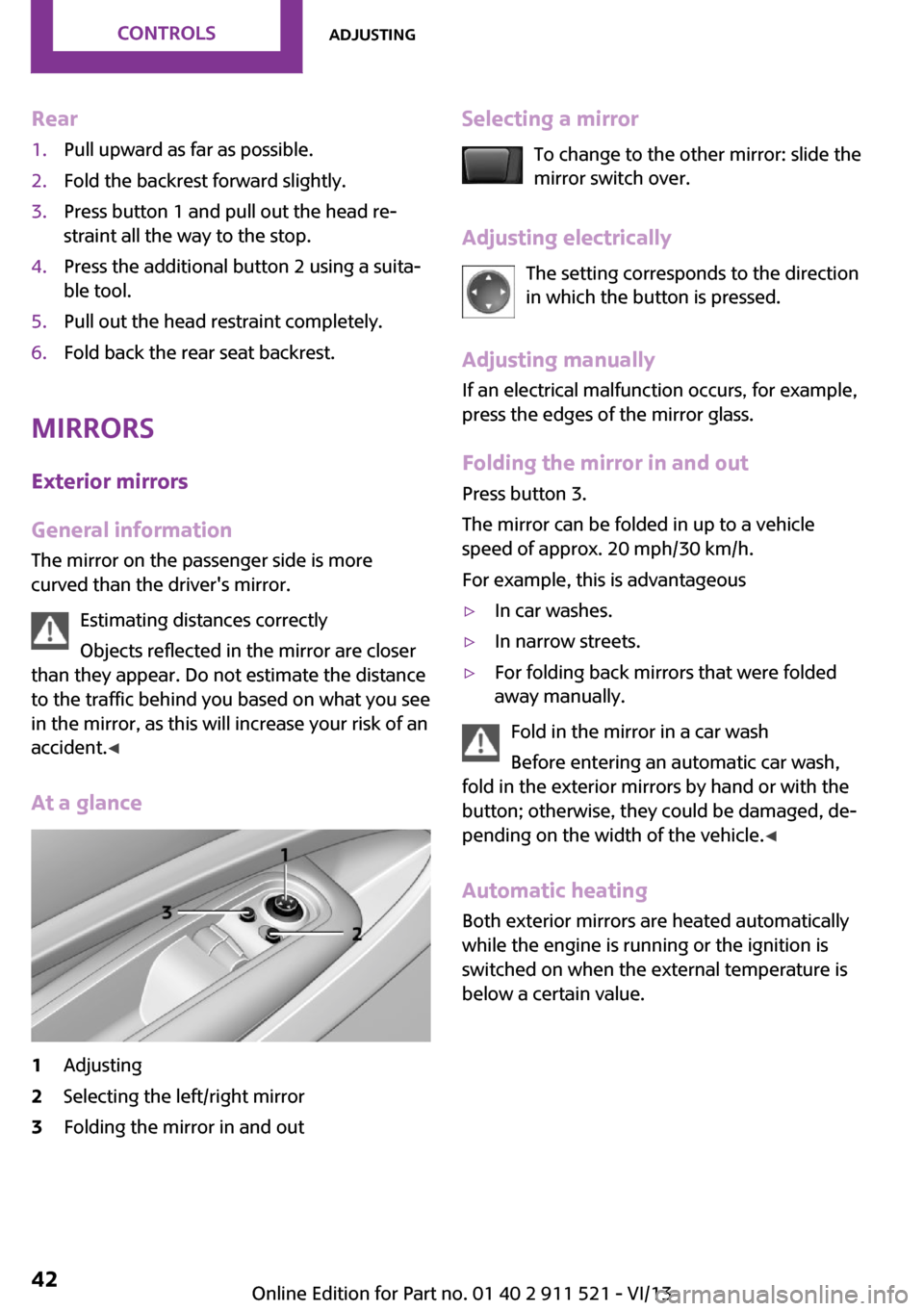
At a glance
1Adjusting2Selecting the left/right mirror3Folding the mirror in and outSelecting a mirror To change to the other mirror: slide the
mirror switch over.
Adjusting electrically The setting corresponds to the direction
in which the button is pressed.
Adjusting manually If an electrical malfunction occurs, for example,
press the edges of the mirror glass.
Folding the mirror in and out
Press button 3.
The mirror can be folded in up to a vehicle
speed of approx. 20 mph/30 km/h.
For example, this is advantageous▷In car washes.▷In narrow streets.▷For folding back mirrors that were folded
away manually.
Fold in the mirror in a car wash
Before entering an automatic car wash,
fold in the exterior mirrors by hand or with the
button; otherwise, they could be damaged, de‐
pending on the width of the vehicle. ◀
Automatic heating Both exterior mirrors are heated automatically
while the engine is running or the ignition is
switched on when the external temperature is
below a certain value.
Seite 42ControlsAdjusting42
Online Edition for Part no. 01 40 2 911 521 - VI/13
Page 49 of 218
DrivingVehicle equipmentThis chapter describes all series equipment as
well as country-specific and special equipment
offered for this model series.Therefore, it also
describes equipment that may not be found in
your vehicle, for instance due to the selected
special equipment or the country version. This
also applies to safety-related functions and sys‐
tems.
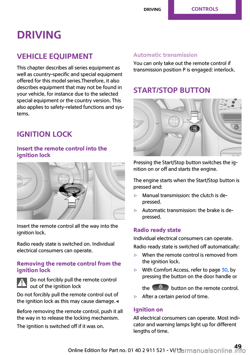
Ignition lock Insert the remote control into the
ignition lock
Insert the remote control all the way into the
ignition lock.
Radio ready state is switched on. Individual
electrical consumers can operate.
Removing the remote control from the
ignition lock
Do not forcibly pull the remote control
out of the ignition lock
Do not forcibly pull the remote control out of
the ignition lock as this may cause damage. ◀
Before removing the remote control, push it all
the way in to release the locking mechanism.
The ignition is switched off if it was on.
Automatic transmission
You can only take out the remote control if
transmission position P is engaged: interlock.
Start/Stop button
Pressing the Start/Stop button switches the ig‐
nition on or off and starts the engine.
The engine starts when the Start/Stop button is
pressed and:
▷Manual transmission: the clutch is de‐
pressed.▷Automatic transmission: the brake is de‐
pressed.
Radio ready state
Individual electrical consumers can operate.
Radio ready state is switched off automatically:
▷When the remote control is removed from
the ignition lock.▷With Comfort Access, refer to page 30, by
pressing the button on the door handle or
the
button on the remote control.
▷After a certain period of time.
Ignition on All electrical consumers can operate. Most indi‐
cator and warning lamps light up for different
lengths of time.
Seite 49DrivingControls49
Online Edition for Part no. 01 40 2 911 521 - VI/13
Page 51 of 218
Engine stop
General information Take the remote control with you
Take the remote control with you when
leaving the vehicle so that children, for exam‐
ple, cannot operate the windows and injure
themselves. ◀
Set the handbrake and further secure the
vehicle as required
Set the handbrake firmly when parking; other‐
wise, the vehicle may roll. On steep upward
and downward inclines, further secure the ve‐
hicle, for example, by turning the steering
wheel in the direction of the curb. ◀
Before driving into a car wash
To make it possible for the vehicle to roll in an
automatic car wash, follow the information on
Washing in automatic car washes, refer to
page 186.
Switching off the engine
Manual transmission1.With the vehicle at a standstill, press the
Start/Stop button.2.Shift into first gear or reverse.3.Set the handbrake firmly.4.Remove the remote control from the igni‐
tion lock.
Automatic transmission
1.Engage transmission position P with the ve‐
hicle stopped.2.Press the Start/Stop button.3.Set the handbrake firmly.4.Remove the remote control from the igni‐
tion lock.Handbrake
The concept
The handbrake is primarily intended to prevent
the vehicle from rolling while parked; it brakes
the rear wheels.
Also follow the instructions under Switching off
the engine, refer to page 51.
Setting
The lever engages automatically.
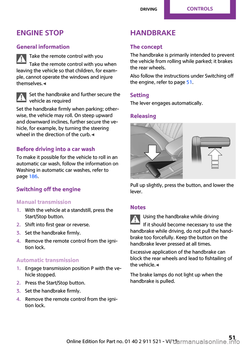
Releasing
Pull up slightly, press the button, and lower the
lever.
Notes Using the handbrake while driving
If it should become necessary to use the
handbrake while driving, do not pull the hand‐
brake too forcefully. Keep the button on the
handbrake lever pressed at all times.
Excessive application of the handbrake can
block the rear wheels and lead to fishtailing of
the vehicle. ◀
The brake lamps do not light up when the
handbrake is pulled.
Seite 51DrivingControls51
Online Edition for Part no. 01 40 2 911 521 - VI/13
Page 54 of 218
Activating intermittent wipe or rain
sensor
Press the button, arrow 3.
The symbol is shown in the tachometer.
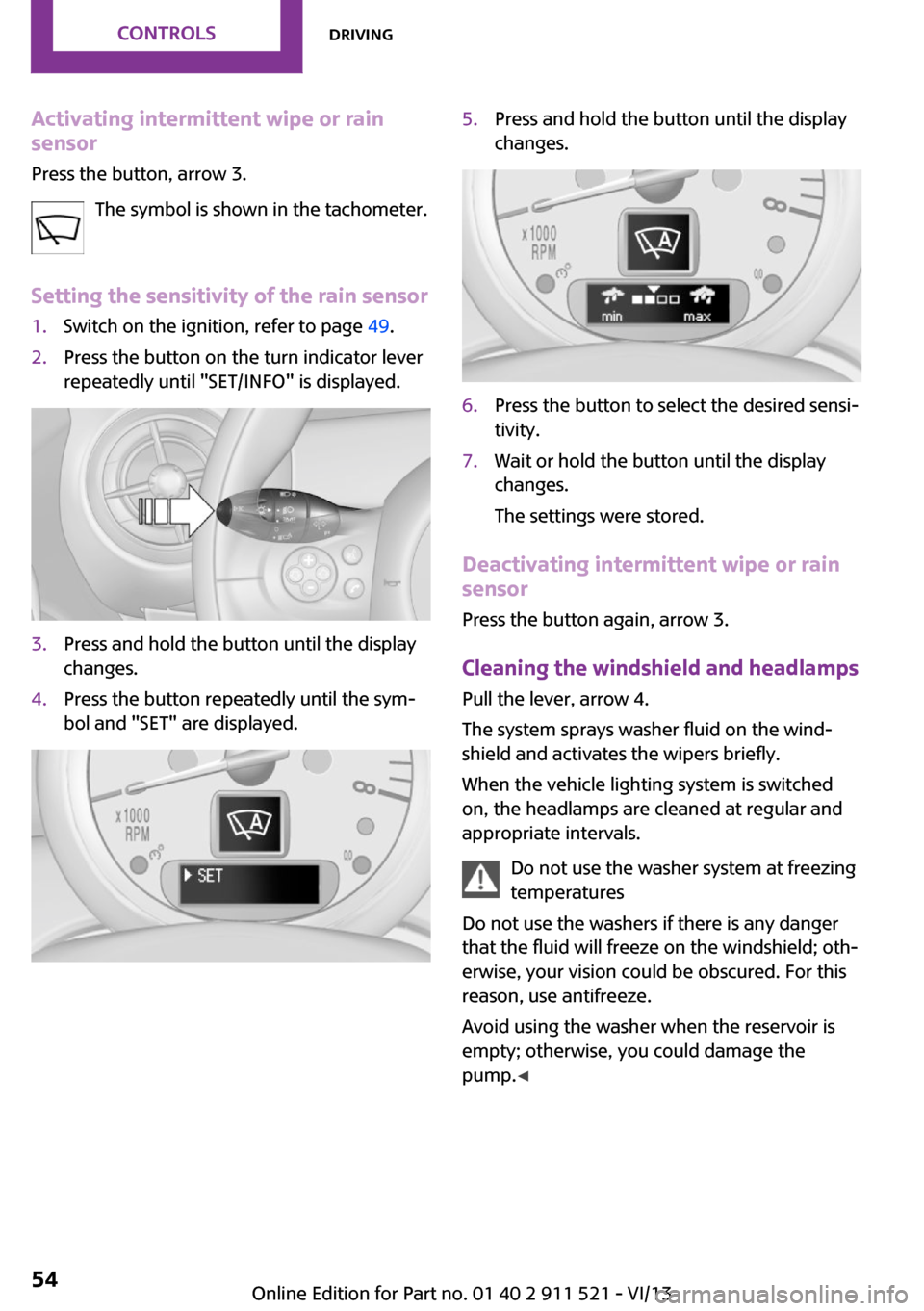
Setting the sensitivity of the rain sensor1.Switch on the ignition, refer to page 49.2.Press the button on the turn indicator lever
repeatedly until "SET/INFO" is displayed.3.Press and hold the button until the display
changes.4.Press the button repeatedly until the sym‐
bol and "SET" are displayed.5.Press and hold the button until the display
changes.6.Press the button to select the desired sensi‐
tivity.7.Wait or hold the button until the display
changes.
The settings were stored.
Deactivating intermittent wipe or rain
sensor
Press the button again, arrow 3.
Cleaning the windshield and headlamps
Pull the lever, arrow 4.
The system sprays washer fluid on the wind‐
shield and activates the wipers briefly.
When the vehicle lighting system is switched
on, the headlamps are cleaned at regular and
appropriate intervals.
Do not use the washer system at freezing
temperatures
Do not use the washers if there is any danger
that the fluid will freeze on the windshield; oth‐
erwise, your vision could be obscured. For this
reason, use antifreeze.
Avoid using the washer when the reservoir is
empty; otherwise, you could damage the
pump. ◀
Seite 54ControlsDriving54
Online Edition for Part no. 01 40 2 911 521 - VI/13
Page 56 of 218
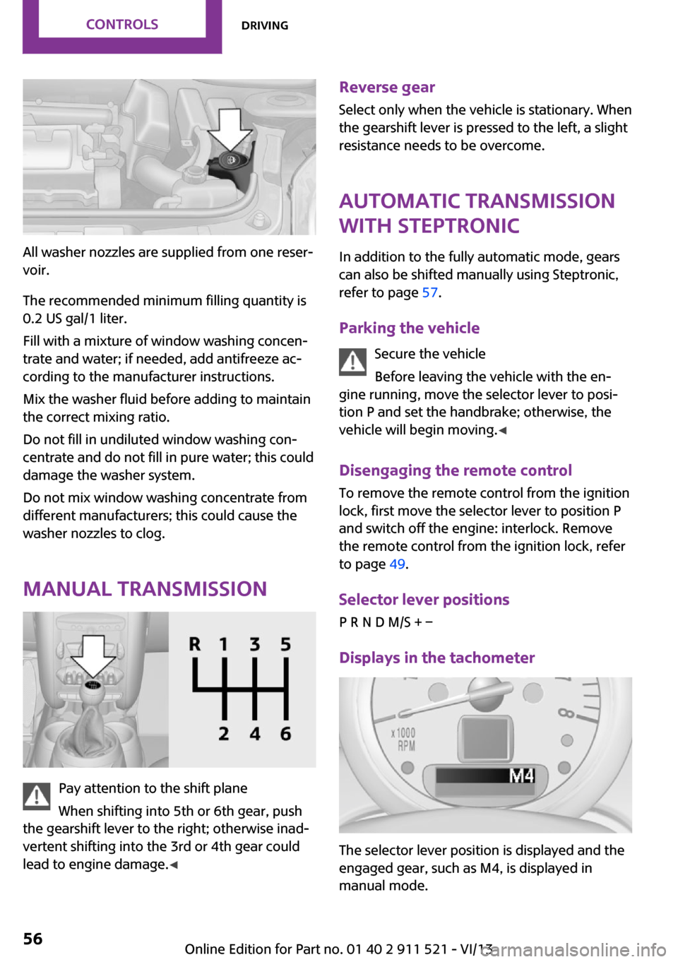
All washer nozzles are supplied from one reser‐
voir.
The recommended minimum filling quantity is
0.2 US gal/1 liter.
Fill with a mixture of window washing concen‐
trate and water; if needed, add antifreeze ac‐
cording to the manufacturer instructions.
Mix the washer fluid before adding to maintain
the correct mixing ratio.
Do not fill in undiluted window washing con‐
centrate and do not fill in pure water; this could
damage the washer system.
Do not mix window washing concentrate from
different manufacturers; this could cause the
washer nozzles to clog.
Manual transmission
Pay attention to the shift plane
When shifting into 5th or 6th gear, push
the gearshift lever to the right; otherwise inad‐
vertent shifting into the 3rd or 4th gear could
lead to engine damage. ◀
Reverse gear
Select only when the vehicle is stationary. When
the gearshift lever is pressed to the left, a slight
resistance needs to be overcome.
Automatic transmission
with Steptronic
In addition to the fully automatic mode, gears
can also be shifted manually using Steptronic,
refer to page 57.
Parking the vehicle Secure the vehicle
Before leaving the vehicle with the en‐
gine running, move the selector lever to posi‐
tion P and set the handbrake; otherwise, the
vehicle will begin moving. ◀
Disengaging the remote control
To remove the remote control from the ignition
lock, first move the selector lever to position P
and switch off the engine: interlock. Remove
the remote control from the ignition lock, refer
to page 49.
Selector lever positions
P R N D M/S + –
Displays in the tachometer
The selector lever position is displayed and the
engaged gear, such as M4, is displayed in
manual mode.
Seite 56ControlsDriving56
Online Edition for Part no. 01 40 2 911 521 - VI/13
Page 59 of 218
DisplaysVehicle equipment
This chapter describes all series equipment as
well as country-specific and special equipment
offered for this model series.Therefore, it also
describes equipment that may not be found in
your vehicle, for instance due to the selected
special equipment or the country version. This
also applies to safety-related functions and sys‐
tems.
Odometer, external tem‐
perature display, clock
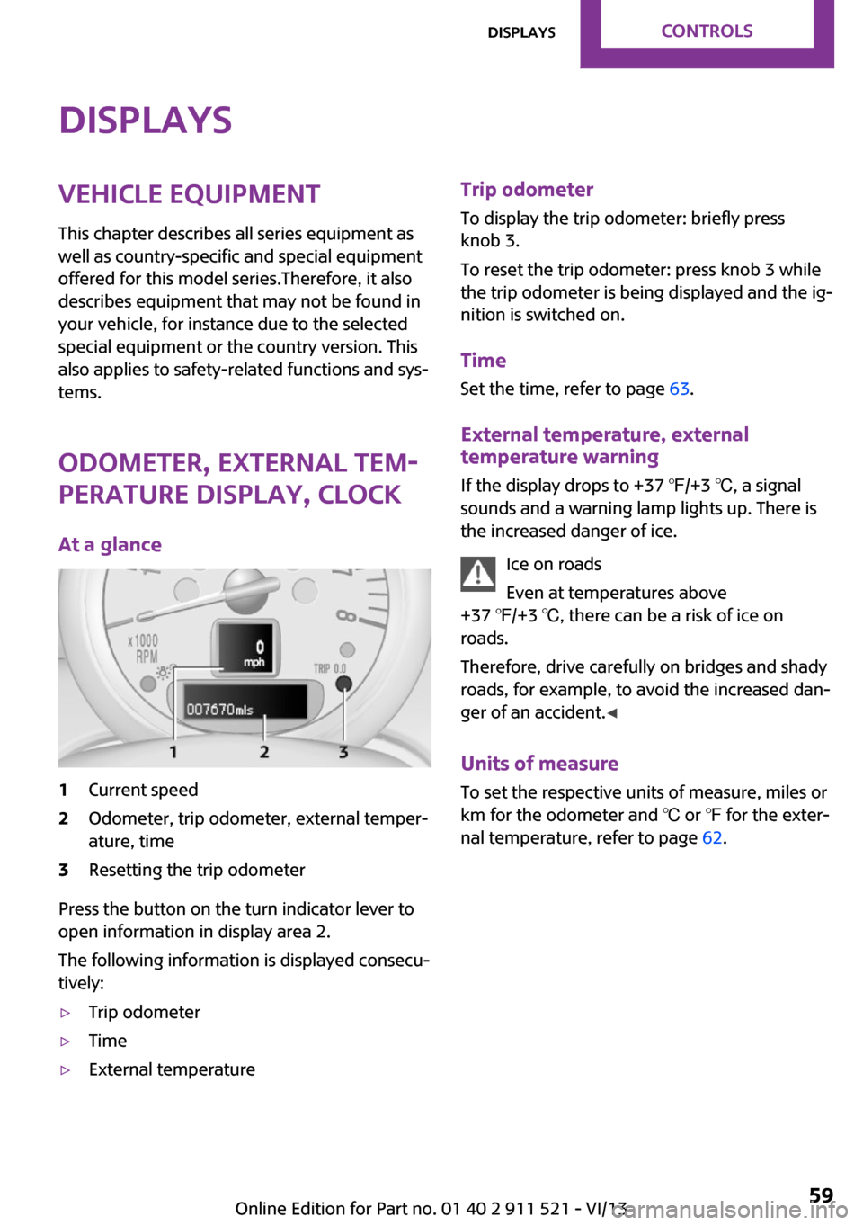
At a glance1Current speed2Odometer, trip odometer, external temper‐
ature, time3Resetting the trip odometer
Press the button on the turn indicator lever to
open information in display area 2.
The following information is displayed consecu‐
tively:
▷Trip odometer▷Time▷External temperatureTrip odometer
To display the trip odometer: briefly press
knob 3.
To reset the trip odometer: press knob 3 while
the trip odometer is being displayed and the ig‐
nition is switched on.
Time Set the time, refer to page 63.
External temperature, external temperature warning
If the display drops to +37 ℉/+3 ℃, a signal
sounds and a warning lamp lights up. There is
the increased danger of ice.
Ice on roads
Even at temperatures above
+37 ℉/+3 ℃, there can be a risk of ice on
roads.
Therefore, drive carefully on bridges and shady
roads, for example, to avoid the increased dan‐
ger of an accident. ◀
Units of measure
To set the respective units of measure, miles or
km for the odometer and ℃ or ℉ for the exter‐
nal temperature, refer to page 62.Seite 59DisplaysControls59
Online Edition for Part no. 01 40 2 911 521 - VI/13