lights MINI Paceman 2014 Owner's Guide
[x] Cancel search | Manufacturer: MINI, Model Year: 2014, Model line: Paceman, Model: MINI Paceman 2014Pages: 218, PDF Size: 5.5 MB
Page 93 of 218
3.Hold the hand-held transmitter of the sys‐
tem to be operated a distance of approx. 1
to 3 in/2.5 to 8 cm away from the buttons
on the interior rearview mirror. The re‐
quired distance depends on the particular
hand-held transmitter.4.Press the button of the desired function on
the hand-held transmitter and the button
being programmed on the interior rearview
mirror simultaneously and hold. The LED on
the interior rearview mirror flashes slowly at
first.5.When the LED flashes more rapidly, release
both buttons. Rapid flashing indicates that
the button on the interior rearview mirror
has been programmed.
If the LED does not flash faster after 60 sec‐
onds, change the distance between the in‐
terior rearview mirror and the hand-held
transmitter and repeat the step. Multiple
trials at different distances may be neces‐
sary. Wait at least 15 seconds between tri‐
als.6.To program additional functions on other
buttons, repeat steps 3 to 5.
The systems can be operated with the buttons
on the interior rearview mirror.
Special characteristics of alternating-
code radio systems
If the system cannot be operated after re‐
peated programming, check whether the sys‐
tem to be operated uses an alternating-code
system.
Read the operating instructions of the system
or press and hold the programmed button on
the interior rearview mirror. If the LED on the
interior rearview mirror flashes rapidly at first
and then lights up continuously for 2 seconds,
the system is equipped with an alternating-
code system. This flashing LED pattern repeats
itself for approx. 20 seconds.
In systems with an alternating-code system, the
universal garage door opener and the system
must be additionally synchronized.
Please obtain additional information on syn‐
chronization in the operating instructions of the
system being set up.
The systems will be easier to synchronize with
the aid of a second person.
Synchronization:1.Park the vehicle within range of the re‐
mote-controlled system.2.Program the corresponding button on the
interior rearview mirror as described.3.Identify and press the synchronization but‐
ton on the system being set up. You have
approx. 30 seconds for the next step.4.Press and hold the button on the interior
rearview mirror for approx. 3 seconds and
then release it. Repeat this step up to three
times if necessary to complete the synchro‐
nization procedure. When synchronization
is completed, the programmed function is
executed.
Reprogramming individual buttons
1.Switch on the ignition.2.Hold the hand-held transmitter at a dis‐
tance of approx. 1 to 3 in/2.5 to 8 cm from
the memory buttons.
The required distance depends on the par‐
ticular hand-held transmitter.3.Press the memory button of the universal
garage door opener.4.If the LED flashes slowly after approx.
20 seconds, press the transmit button on
the hand-held transmitter.5.Release both buttons when the LED flashes
rapidly.
If the LED does not flash rapidly after ap‐
prox. 60 seconds, change the distance and
repeat the step.Seite 93Interior equipmentControls93
Online Edition for Part no. 01 40 2 911 521 - VI/13
Page 94 of 218
Canada: if the LED does not flash rapidly af‐
ter approx. 60 seconds, change the dis‐
tance and repeat the step. If programming
was aborted by the hand-held transmitter,
hold down the memory button and press
and release the button on the hand-held
transmitter several times for 2 seconds.
Controls
Prior to operation
Before operating a unit with the Universal
Garage Door Opener, ensure that there are no
people, animals, or objects in the range of
movement of the system; otherwise, there is a
risk of injury or damage.
Also follow the safety instructions of the hand-
held transmitter. ◀
The system, such as the garage door, can be
operated using the button on the interior rear‐
view mirror with the engine running or the igni‐
tion switched on. When you are within the re‐
ception range of the system, press and hold the
button until the function is initiated. The LED on
the interior rearview mirror lights up continu‐
ously while the radio signal is being transmit‐
ted.
Deleting stored functions
Press the right and left buttons on the interior
rearview mirror simultaneously for approx.
20 seconds until the LED flashes rapidly. All
stored functions are deleted. The functions can‐
not be deleted individually.
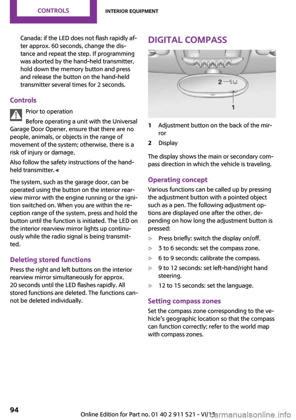
Digital compass1Adjustment button on the back of the mir‐
ror2Display
The display shows the main or secondary com‐
pass direction in which the vehicle is traveling.
Operating concept
Various functions can be called up by pressing
the adjustment button with a pointed object
such as a pen. The following adjustment op‐
tions are displayed one after the other, de‐
pending on how long the adjustment button is
pressed:
▷Press briefly: switch the display on/off.▷3 to 6 seconds: set the compass zone.▷6 to 9 seconds: calibrate the compass.▷9 to 12 seconds: set left-hand/right hand
steering.▷12 to 15 seconds: set the language.
Setting compass zones
Set the compass zone corresponding to the ve‐
hicle's geographic location so that the compass
can function correctly; refer to the world map
with compass zones.
Seite 94ControlsInterior equipment94
Online Edition for Part no. 01 40 2 911 521 - VI/13
Page 119 of 218
Switch off the engine during longer
stops
Switch off the engine during longer stops, e.g.,
at traffic lights, railroad crossings or in traffic
congestion.
Fuel savings are already achieved after the en‐
gine is turned off for as little as 4 seconds.
Automatic Engine Start/Stop Function
The Automatic Engine Start/Stop Function auto‐
matically switches the engine off during a stop.
If the engine is stopped and then started again,
fuel consumption and emissions drop com‐
pared to an engine that runs permanently.
Stopping the engine even for just a few sec‐
onds can result in savings.
In addition, fuel consumption depends on other
factors as well, such as driving style, road con‐
ditions, maintenance, and environmental fac‐
tors.
Switch off any functions that are not currently needed
Functions such as seat heating and the rear
window defroster require a lot of energy and
consume additional fuel, especially in city and
stop-and-go traffic.
Therefore, switch off these functions if they are
not actually needed.
Have maintenance carried out
Have vehicles maintained regularly to achieve
optimal vehicle economy and operating life.
Have the maintenance carried out by the serv‐
ice center.
Please also note the MINI maintenance system,
refer to page 169.Seite 119Saving fuelDriving tips119
Online Edition for Part no. 01 40 2 911 521 - VI/13
Page 168 of 218
CoolantVehicle equipment
This chapter describes all series equipment as
well as country-specific and special equipment
offered for this model series.Therefore, it also
describes equipment that may not be found in
your vehicle, for instance due to the selected
special equipment or the country version. This
also applies to safety-related functions and sys‐
tems.
General information Danger of burns from hot engine
Do not open the cooling system while the
engine is hot; otherwise, escaping coolant may
cause burns. ◀
Suitable additives
Only use suitable additives; otherwise,
engine damage may occur. The additives are
harmful to your health. ◀
Coolant consists of water and additives.
Not all commercially available additives are
suitable for your MINI vehicle. Ask your service
center for suitable additives.
Coolant temperature
If the coolant and therefore the engine over‐
heat, a warning lamp lights up, refer to
page 190.
Coolant level
Checking1.Do not open the hood until the engine has
cooled down.2.Turn the expansion tank cap counterclock‐
wise slightly to allow any accumulated
pressure to escape; then continue turning
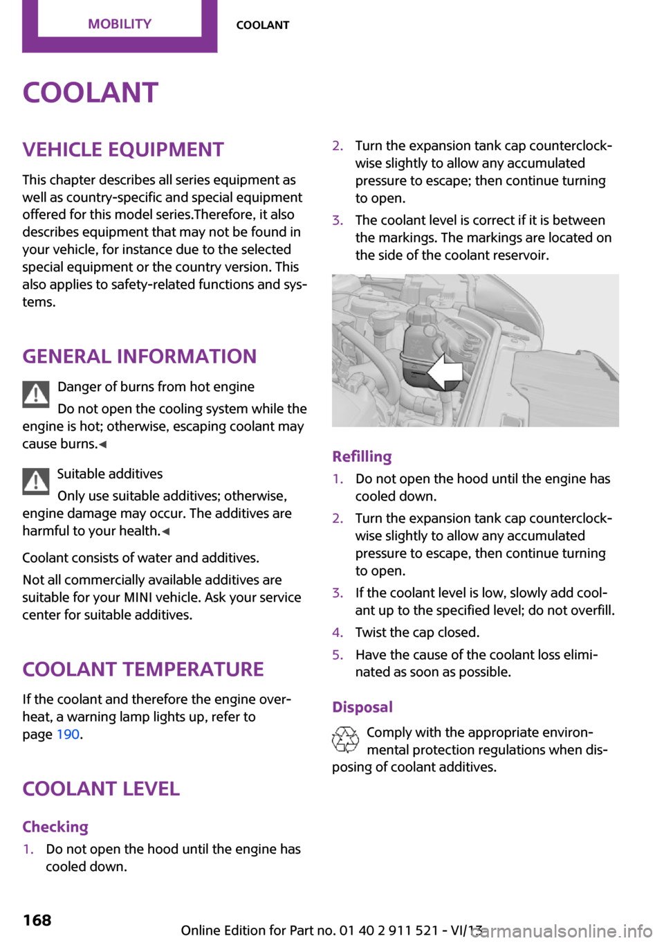
to open.3.The coolant level is correct if it is between
the markings. The markings are located on
the side of the coolant reservoir.
Refilling
1.Do not open the hood until the engine has
cooled down.2.Turn the expansion tank cap counterclock‐
wise slightly to allow any accumulated
pressure to escape, then continue turning
to open.3.If the coolant level is low, slowly add cool‐
ant up to the specified level; do not overfill.4.Twist the cap closed.5.Have the cause of the coolant loss elimi‐
nated as soon as possible.
Disposal
Comply with the appropriate environ‐mental protection regulations when dis‐
posing of coolant additives.
Seite 168MobilityCoolant168
Online Edition for Part no. 01 40 2 911 521 - VI/13
Page 170 of 218
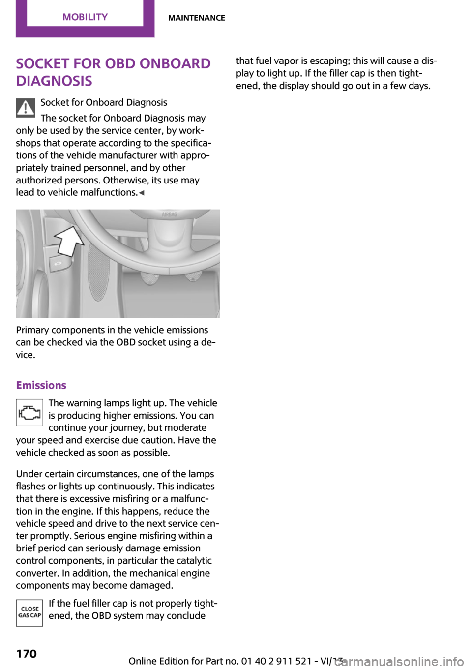
Socket for OBD Onboard
Diagnosis
Socket for Onboard Diagnosis
The socket for Onboard Diagnosis may
only be used by the service center, by work‐
shops that operate according to the specifica‐
tions of the vehicle manufacturer with appro‐
priately trained personnel, and by other
authorized persons. Otherwise, its use may
lead to vehicle malfunctions. ◀
Primary components in the vehicle emissions
can be checked via the OBD socket using a de‐
vice.
Emissions The warning lamps light up. The vehicle
is producing higher emissions. You can
continue your journey, but moderate
your speed and exercise due caution. Have the
vehicle checked as soon as possible.
Under certain circumstances, one of the lamps
flashes or lights up continuously. This indicates
that there is excessive misfiring or a malfunc‐
tion in the engine. If this happens, reduce the
vehicle speed and drive to the next service cen‐
ter promptly. Serious engine misfiring within a
brief period can seriously damage emission
control components, in particular the catalytic
converter. In addition, the mechanical engine
components may become damaged.
If the fuel filler cap is not properly tight‐
ened, the OBD system may conclude
that fuel vapor is escaping; this will cause a dis‐
play to light up. If the filler cap is then tight‐
ened, the display should go out in a few days.Seite 170MobilityMaintenance170
Online Edition for Part no. 01 40 2 911 521 - VI/13
Page 172 of 218
Lamp and bulb replace‐
ment
Notes
Lamps and bulbs Lamps and bulbs make an essential contribu‐
tion to vehicle safety. Therefore, exercise cau‐
tion when handling lamps and bulbs.
The manufacturer of the vehicle recommends
that you entrust corresponding procedures to
the service center if you are unfamiliar with
them or they are not described here.
You can obtain a selection of replacement
bulbs at the service center.
Danger of burns
Only change bulbs when they are cool;
otherwise, there is the danger of getting
burned. ◀
Working on the lighting system
When working on the lighting system,
you should always switch off the lights affected
to prevent short circuits.
To avoid possible injury or equipment damage
when replacing bulbs, observe any instructions
provided by the bulb manufacturer. ◀
Do not touch the bulbs
Do not touch the glass of new bulbs with
your bare hands, as even minute amounts of
contamination will burn into the bulb's surface
and reduce its service life.
Use a clean tissue, cloth or something similar,
or hold the bulb by its base. ◀
Caring for the headlamps, refer to page 187.
For bulb replacement that is not described
here, please contact the service center or a
workshop that works according to the repair
procedures of the manufacturer with corre‐
spondingly trained personnel.For checking and adjusting headlamp aim,
please contact your MINI dealer.
Light-emitting diodes LEDs Light-emitting diodes installed behind translu‐
cent lenses serve as the light source for many
of the controls and displays in the vehicle.
These light-emitting diodes, which operate us‐
ing a concept similar to that applied in conven‐
tional lasers, are officially designated as Class 1
light-emitting diodes.
Do not remove the covers
Do not remove the covers, and never
stare into the unfiltered light for several hours;
otherwise, irritation of the retina could result. ◀
Headlamp glass
Condensation can form on the inside of the
headlamps in cool or humid weather. When the
light is switched on, the condensation evapo‐ rates after a short time. The headlamps do notneed to be changed.
If the condensation in the headlamps does not
evaporate after trips with the lights switched
on, and the amount of moisture in the head‐
lamps increases, for example if water droplets
form, have them checked by your service cen‐
ter.
Bi-xenon headlamps These bulbs have a very long life and the likeli‐
hood of failure is very low, provided that they
are not switched on and off excessively. If a
bulb should nevertheless fail, you can continue
driving cautiously with the front fog lamps, pro‐
vided this is permitted by local laws.
Do not perform work/bulb replacement
on xenon headlamps
Have any work on the xenon lighting system,
including bulb replacement, performed only by
a service center.Seite 172MobilityReplacing components172
Online Edition for Part no. 01 40 2 911 521 - VI/13
Page 190 of 218
Indicator/warning lampsVehicle equipment
This chapter describes all series equipment as
well as country-specific and special equipment
offered for this model series.Therefore, it alsodescribes equipment that may not be found in
your vehicle, for instance due to the selected
special equipment or the country version. This
also applies to safety-related functions and sys‐
tems.
Overview
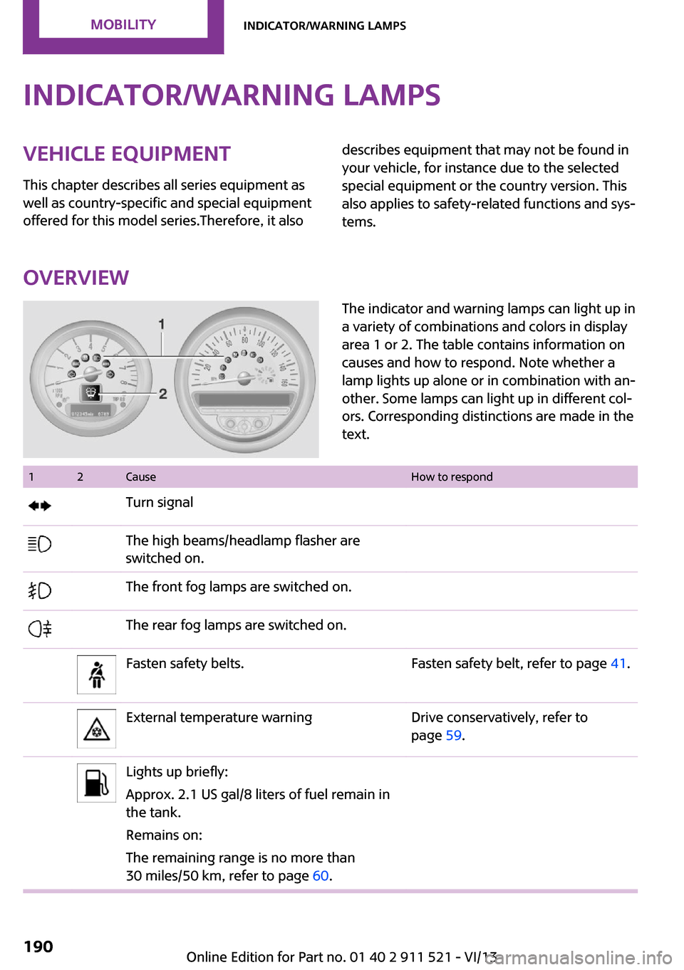
The indicator and warning lamps can light up in
a variety of combinations and colors in display
area 1 or 2. The table contains information on
causes and how to respond. Note whether a
lamp lights up alone or in combination with an‐
other. Some lamps can light up in different col‐
ors. Corresponding distinctions are made in the
text. 12CauseHow to respondTurn signalThe high beams/headlamp flasher are
switched on.The front fog lamps are switched on.The rear fog lamps are switched on.Fasten safety belts.Fasten safety belt, refer to page 41.External temperature warningDrive conservatively, refer to
page 59.Lights up briefly:
Approx. 2.1 US gal/8 liters of fuel remain in
the tank.
Remains on:
The remaining range is no more than
30 miles/50 km, refer to page 60.Seite 190MobilityIndicator/warning lamps190
Online Edition for Part no. 01 40 2 911 521 - VI/13
Page 191 of 218
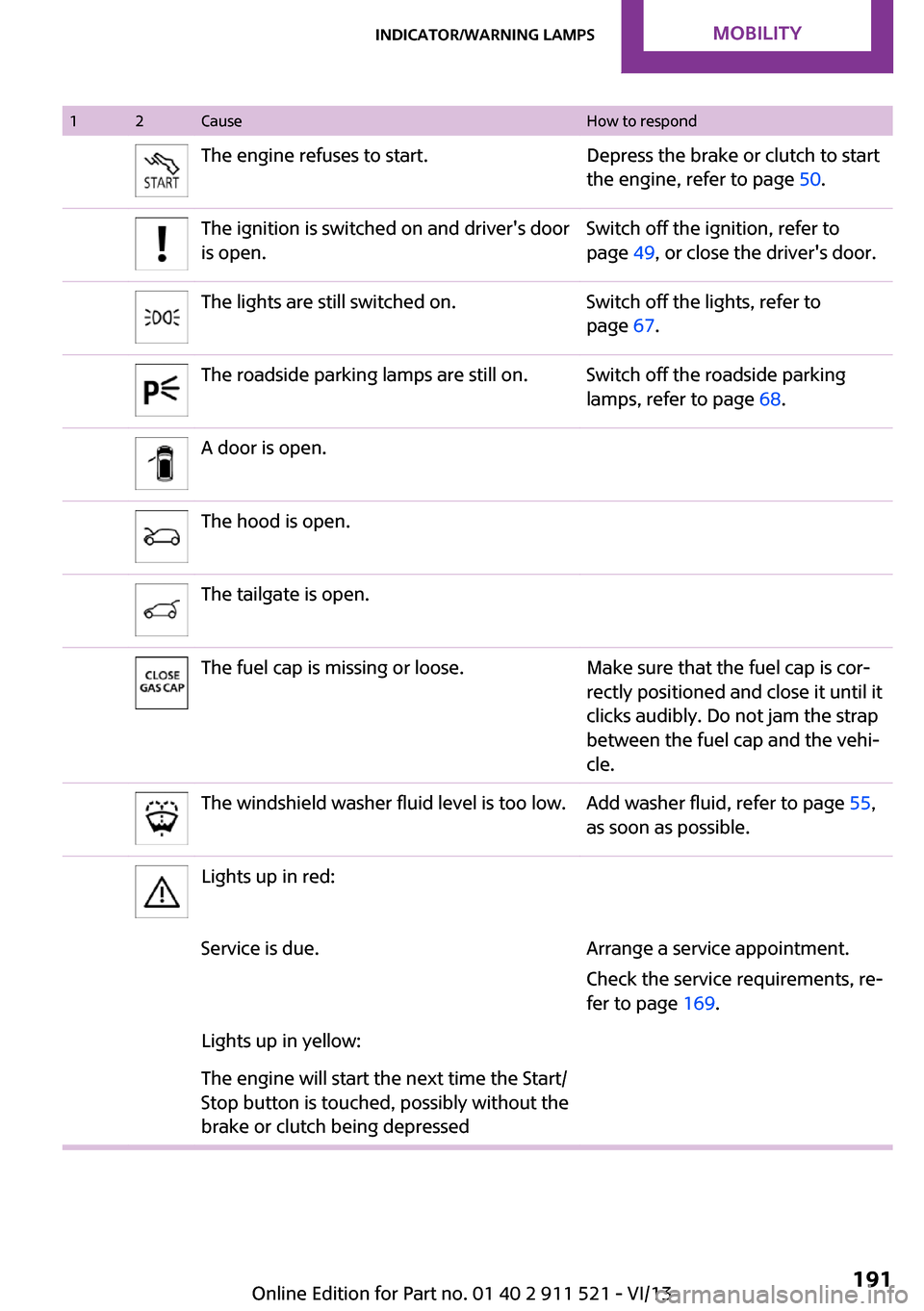
12CauseHow to respondThe engine refuses to start.Depress the brake or clutch to start
the engine, refer to page 50.The ignition is switched on and driver's door
is open.Switch off the ignition, refer to
page 49, or close the driver's door.The lights are still switched on.Switch off the lights, refer to
page 67.The roadside parking lamps are still on.Switch off the roadside parking
lamps, refer to page 68.A door is open.The hood is open.The tailgate is open.The fuel cap is missing or loose.Make sure that the fuel cap is cor‐
rectly positioned and close it until it
clicks audibly. Do not jam the strap
between the fuel cap and the vehi‐
cle.The windshield washer fluid level is too low.Add washer fluid, refer to page 55,
as soon as possible.Lights up in red:Service is due.Arrange a service appointment.
Check the service requirements, re‐
fer to page 169.Lights up in yellow:The engine will start the next time the Start/
Stop button is touched, possibly without the
brake or clutch being depressedSeite 191Indicator/warning lampsMobility191
Online Edition for Part no. 01 40 2 911 521 - VI/13
Page 192 of 218
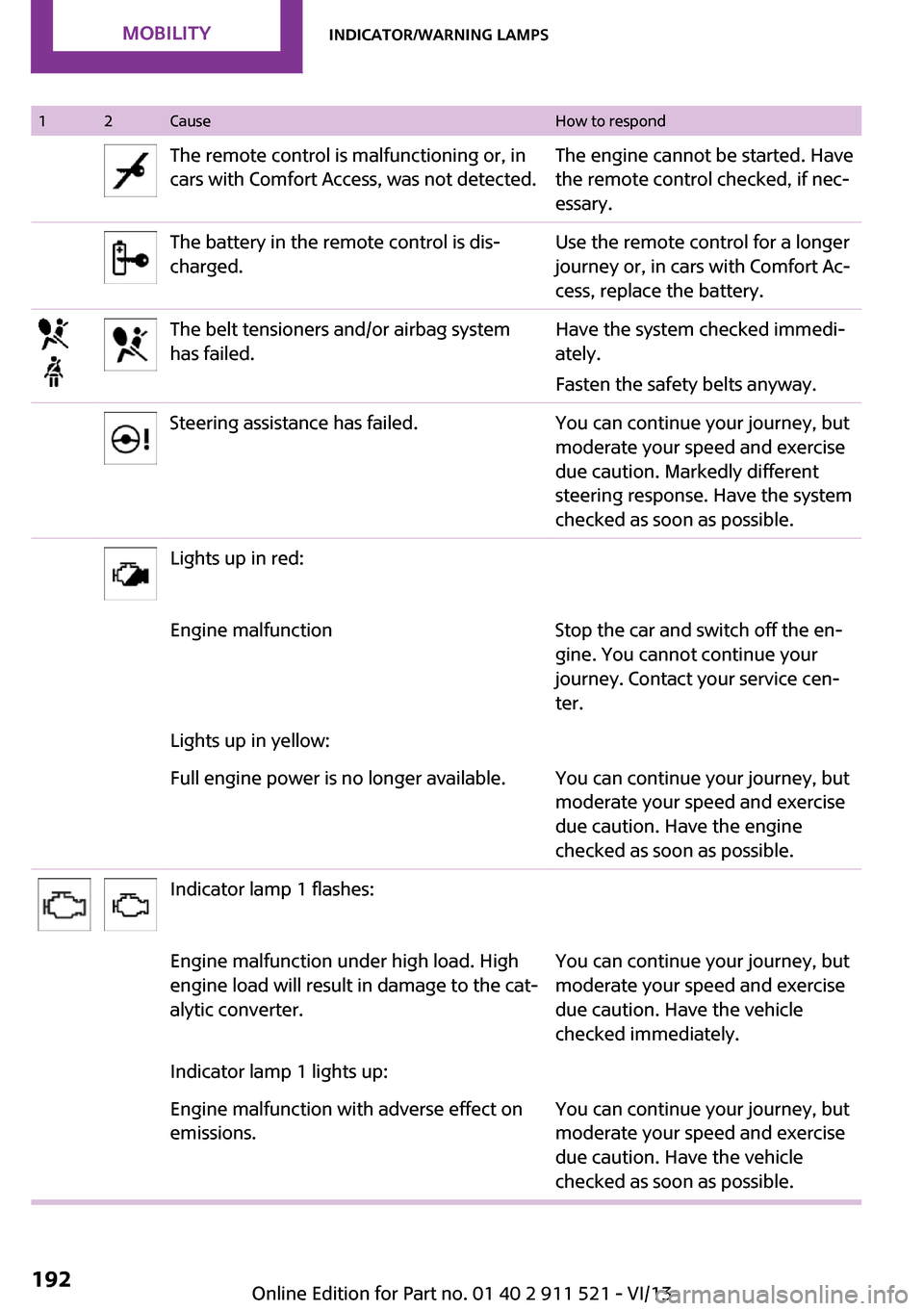
12CauseHow to respondThe remote control is malfunctioning or, in
cars with Comfort Access, was not detected.The engine cannot be started. Have
the remote control checked, if nec‐
essary.The battery in the remote control is dis‐
charged.Use the remote control for a longer
journey or, in cars with Comfort Ac‐
cess, replace the battery.The belt tensioners and/or airbag system
has failed.Have the system checked immedi‐
ately.
Fasten the safety belts anyway.Steering assistance has failed.You can continue your journey, but
moderate your speed and exercise
due caution. Markedly different
steering response. Have the system
checked as soon as possible.Lights up in red:Engine malfunctionStop the car and switch off the en‐
gine. You cannot continue your
journey. Contact your service cen‐
ter.Lights up in yellow:Full engine power is no longer available.You can continue your journey, but
moderate your speed and exercise
due caution. Have the engine
checked as soon as possible.Indicator lamp 1 flashes:Engine malfunction under high load. High
engine load will result in damage to the cat‐
alytic converter.You can continue your journey, but
moderate your speed and exercise
due caution. Have the vehicle
checked immediately.Indicator lamp 1 lights up:Engine malfunction with adverse effect on
emissions.You can continue your journey, but
moderate your speed and exercise
due caution. Have the vehicle
checked as soon as possible.Seite 192MobilityIndicator/warning lamps192
Online Edition for Part no. 01 40 2 911 521 - VI/13
Page 193 of 218
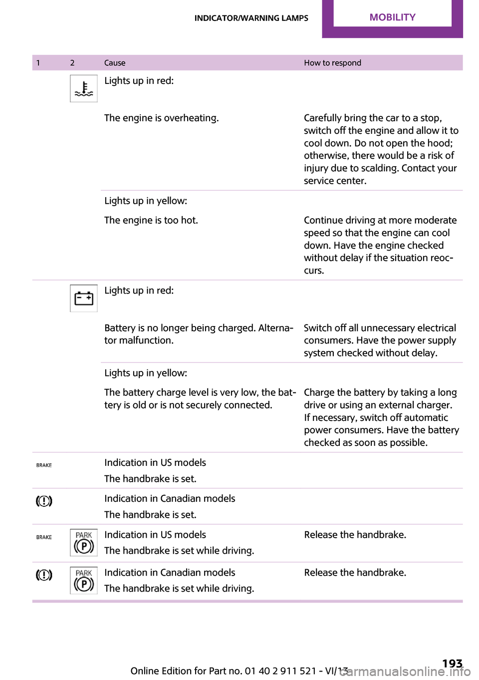
12CauseHow to respondLights up in red:The engine is overheating.Carefully bring the car to a stop,
switch off the engine and allow it to
cool down. Do not open the hood;
otherwise, there would be a risk of
injury due to scalding. Contact your
service center.Lights up in yellow:The engine is too hot.Continue driving at more moderate
speed so that the engine can cool
down. Have the engine checked
without delay if the situation reoc‐
curs.Lights up in red:Battery is no longer being charged. Alterna‐
tor malfunction.Switch off all unnecessary electrical
consumers. Have the power supply
system checked without delay.Lights up in yellow:The battery charge level is very low, the bat‐
tery is old or is not securely connected.Charge the battery by taking a long
drive or using an external charger.
If necessary, switch off automatic
power consumers. Have the battery
checked as soon as possible.Indication in US models
The handbrake is set.Indication in Canadian models
The handbrake is set.Indication in US models
The handbrake is set while driving.Release the handbrake.Indication in Canadian models
The handbrake is set while driving.Release the handbrake.Seite 193Indicator/warning lampsMobility193
Online Edition for Part no. 01 40 2 911 521 - VI/13