remote control MINI Paceman 2014 Owner's Guide
[x] Cancel search | Manufacturer: MINI, Model Year: 2014, Model line: Paceman, Model: MINI Paceman 2014Pages: 218, PDF Size: 5.5 MB
Page 89 of 218
Microfilter
The microfilter traps dust and pollen. The mi‐
crofilter is changed by the service center during
routine maintenance work.
Microfilter/activated-charcoal filter
The microfilter traps dust and pollen. The acti‐
vated-charcoal filter provides additional protec‐tion by filtering gaseous pollutants from the
outside air. The service center replaces this
combined filter during routine maintenance.
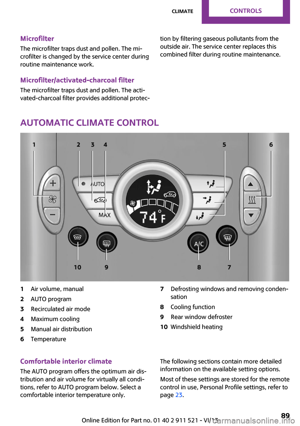
Automatic climate control
1Air volume, manual2AUTO program3Recirculated air mode4Maximum cooling5Manual air distribution6Temperature7Defrosting windows and removing conden‐
sation8Cooling function9Rear window defroster10Windshield heatingComfortable interior climate
The AUTO program offers the optimum air dis‐tribution and air volume for virtually all condi‐
tions, refer to AUTO program below. Select a
comfortable interior temperature only.The following sections contain more detailed
information on the available setting options.
Most of these settings are stored for the remote
control in use, Personal Profile settings, refer to
page 23.Seite 89ClimateControls89
Online Edition for Part no. 01 40 2 911 521 - VI/13
Page 92 of 218
Interior equipmentVehicle equipmentThis chapter describes all series equipment as
well as country-specific and special equipment
offered for this model series.Therefore, it also
describes equipment that may not be found in
your vehicle, for instance due to the selected
special equipment or the country version. This
also applies to safety-related functions and sys‐
tems.
Universal garage door
opener
The concept
The universal garage door opener can be used
to operate up to 3 functions in remote-control‐
led systems, such as garage door drives or
lighting systems. The universal garage door
opener replaces up to 3 different hand-held
transmitters. To operate it, the buttons on the
interior rearview mirror must be programmed
for the desired functions. The hand-held trans‐
mitter for the system is needed for the pro‐
gramming procedure.
During programming
During programming and before activat‐
ing a device using the Universal Garage Door
Opener, ensure that there are no people, ani‐
mals, or objects in the range of movement of
the remote-controlled device; otherwise, there
is a risk of injury or damage.
Also follow the safety instructions of the hand-
held transmitter. ◀
Before selling the vehicle, delete the stored
functions for security reasons.Compatibility
If this symbol is printed on the packag‐
ing or in the operating instructions of
the system being operated, the system
is generally compatible with the universal ga‐
rage door opener.
If you have any questions, please contact:▷Your service center.▷www.homelink.com on the Internet.
HomeLink is a registered trademark of Johnson
Controls, Inc.
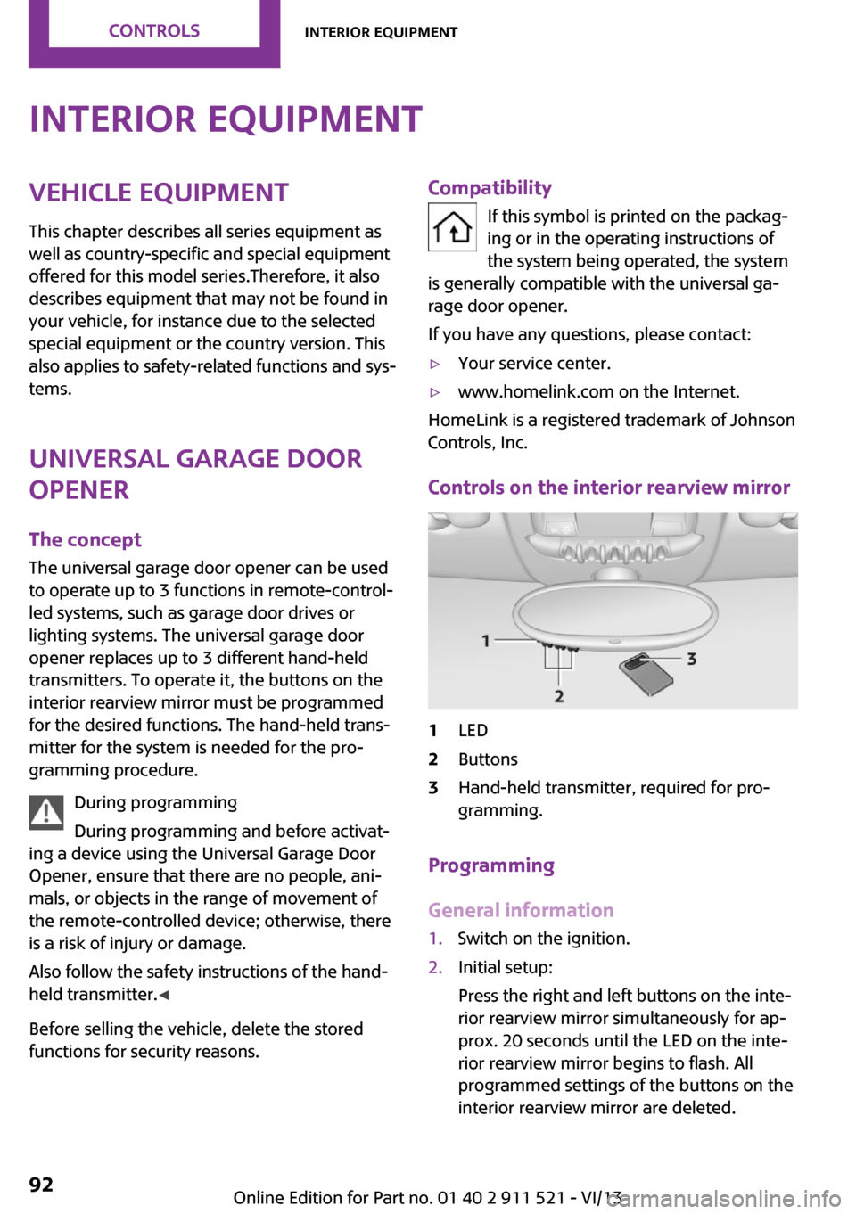
Controls on the interior rearview mirror
1LED2Buttons3Hand-held transmitter, required for pro‐
gramming.
Programming
General information
1.Switch on the ignition.2.Initial setup:
Press the right and left buttons on the inte‐
rior rearview mirror simultaneously for ap‐
prox. 20 seconds until the LED on the inte‐
rior rearview mirror begins to flash. All
programmed settings of the buttons on the
interior rearview mirror are deleted.Seite 92ControlsInterior equipment92
Online Edition for Part no. 01 40 2 911 521 - VI/13
Page 96 of 218
Cupholders and ashtray/
lighter
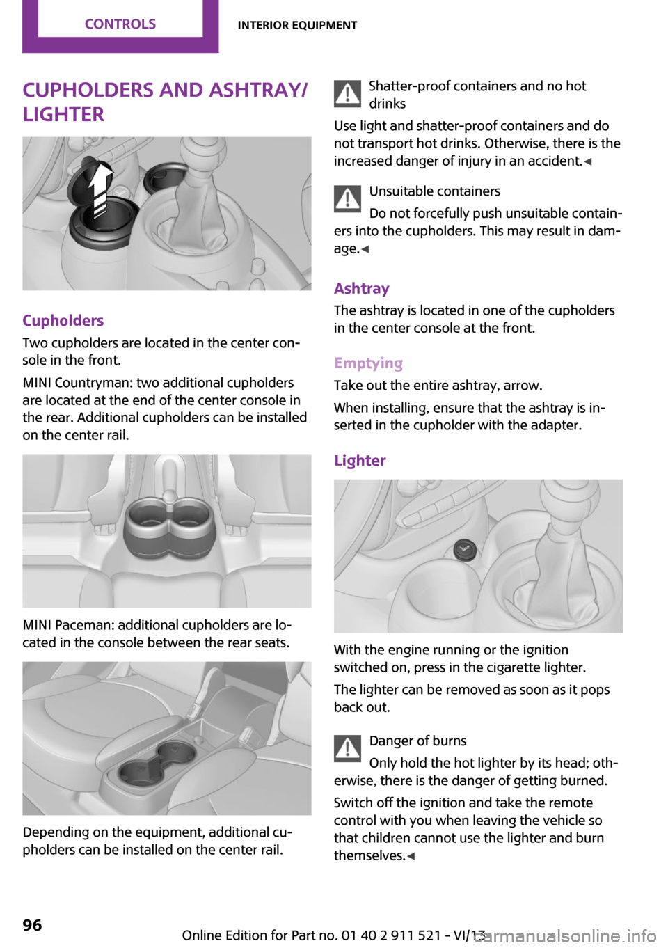
Cupholders
Two cupholders are located in the center con‐
sole in the front.
MINI Countryman: two additional cupholders
are located at the end of the center console in
the rear. Additional cupholders can be installed
on the center rail.
MINI Paceman: additional cupholders are lo‐
cated in the console between the rear seats.
Depending on the equipment, additional cu‐
pholders can be installed on the center rail.
Shatter-proof containers and no hot
drinks
Use light and shatter-proof containers and do
not transport hot drinks. Otherwise, there is the
increased danger of injury in an accident. ◀
Unsuitable containers
Do not forcefully push unsuitable contain‐
ers into the cupholders. This may result in dam‐
age. ◀
Ashtray The ashtray is located in one of the cupholders
in the center console at the front.
Emptying Take out the entire ashtray, arrow.
When installing, ensure that the ashtray is in‐
serted in the cupholder with the adapter.
Lighter
With the engine running or the ignition
switched on, press in the cigarette lighter.
The lighter can be removed as soon as it pops
back out.
Danger of burns
Only hold the hot lighter by its head; oth‐
erwise, there is the danger of getting burned.
Switch off the ignition and take the remote
control with you when leaving the vehicle so
that children cannot use the lighter and burn
themselves. ◀
Seite 96ControlsInterior equipment96
Online Edition for Part no. 01 40 2 911 521 - VI/13
Page 124 of 218
Adjusting the volumeTurn the left knob. The setting is stored for the
remote control currently in use.
When a call is placed using the hands-free sys‐
tem, the audio sources are muted.
Speed-dependent volume and volumes
of PDC signal tone and gong▷"PDC": volume of the PDC signal tone com‐
pared to the audio sources.▷"GONG": volume of the gong compared to
the audio sources.▷"S-VOL": speed-dependent volume control.
Set the audio sources to a high volume to be
able to adjust the volume of the signal tones
more easily.
1. Press the button.2. Select the symbol if necessary.3.Select the desired volume setting.4.Set the desired volume and press the right
knob.
Volume of external audio devices
An external audio device such as an MP3 player
can be connected via the AUX-IN port in the
center console and the audio tracks can be
played over the car's loudspeaker system.
The volume of the external audio device can be
adjusted to the car radio.
1. Press the button.2."AUX"3."Vol-AUX"4.Set the desired volume and press the right
knob.
Tone settings
▷"BASS": depth adjustment.▷"TREBLE": treble adjustment.▷"FADER": front/rear volume distribution.▷"BAL": left/right volume distribution.
The sound settings are set globally for all audio
sources.
Setting the treble, bass, and volume distribution
1. Press the button.2.Highlight the desired tone setting and press
the right knob.3.Create the desired setting and press the
right knob.
Resetting the tone settings
The tone settings are reset to medium values.
1. Press the button.2."RESET"
Time
Setting the time, date, and time format
1.Switch on the radio ready state or the igni‐
tion.2. Press the button.3."CONFIG"4."TIME"5.Select the desired category.6.Create the settings and press the right
knob.
Setting the units of measure of the
computer and the language
1.Switch on the radio ready state or the igni‐
tion.2. Press the button.3."CONFIG"4.▷"DIST": change the unit of measure for
the range.Seite 124EntertainmentRadio MINI Boost CD124
Online Edition for Part no. 01 40 2 911 521 - VI/13
Page 125 of 218
▷"LANG": select the language of the dis‐
play texts.▷"CONSMP": change the unit of measure
for the average fuel consumption.▷"TEMP": change the unit of measure for
the external temperature.5.Highlight the desired menu item and press
the button.6.Create the desired setting.
Computer
The following vehicle information can be call up
via the computer:
▷Average fuel consumption▷Average speed▷Range
Displaying information
1.Switch on the radio ready state or the igni‐
tion.2. Press the button.3."COMP"
Average fuel consumption
The average fuel consumption is calculated for
the time during which the engine is running.
To start calculation of the average fuel con‐
sumption:
1."CONSMP"2."RESET"
The previous display is set to zero and the sys‐
tem begins recalculating the average fuel con‐
sumption.
Average speed
The average speed is calculated for the time
during which the engine is running.
To start calculation of the average speed:
1."SPEED"2."RESET"
Estimated range
"RANGE"
The display shows the estimated distance that
can be still be driven on the remaining fuel,
taking into consideration the driving style over
the last 18 miles/30 km.
Radio
Listening to the radio
The radio is designed for reception in the FM
and AM wavebands.
1.Switch on the radio, refer to page 123.2. Press this button if necessary.3."TUNER"4."FM" or"AM"
Press the corresponding button repeatedly
until the desired waveband is displayed.▷FM: FM1, FM2, FMA▷AM: AM, AMA
Selecting a station
The setting is stored for the remote control cur‐
rently in use.
Next station
Press the button.
The next station with reception is selected.
Selecting the station manually by
frequency
1. Press the button.2.▷Press the respective function button to
set the desired frequency.▷Turn the right knob until the desired
frequency is set.Seite 125Radio MINI Boost CDEntertainment125
Online Edition for Part no. 01 40 2 911 521 - VI/13
Page 140 of 218
▷Dial a stored phone number, such as from
the list of accepted calls.▷End the call.
When the ignition and the radio ready state are
switched off, such as after the remote control is
removed, an existing call can be continued for
up to 25 minutes on the hands-free system.
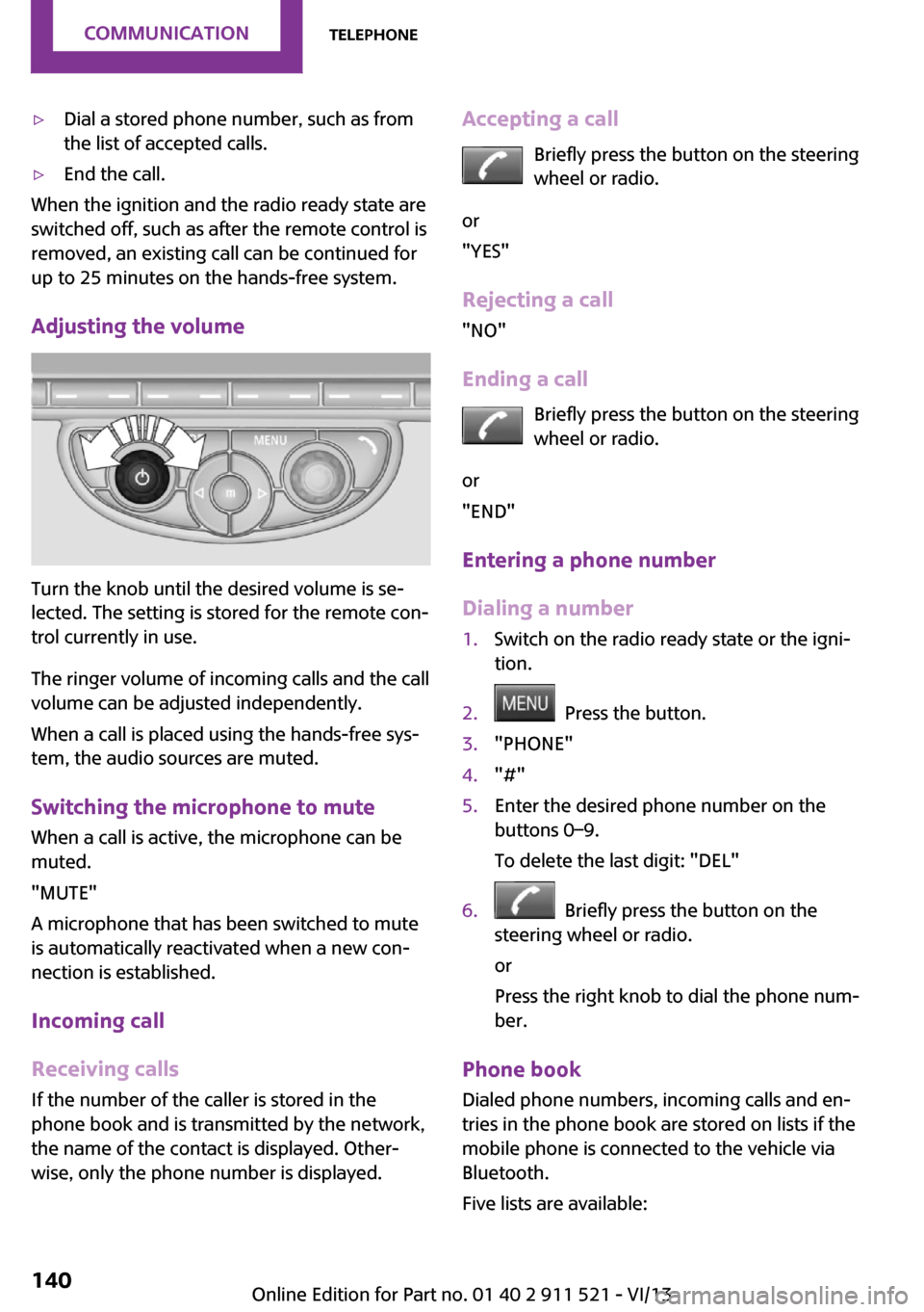
Adjusting the volume
Turn the knob until the desired volume is se‐
lected. The setting is stored for the remote con‐
trol currently in use.
The ringer volume of incoming calls and the call
volume can be adjusted independently.
When a call is placed using the hands-free sys‐
tem, the audio sources are muted.
Switching the microphone to mute
When a call is active, the microphone can be
muted.
"MUTE"
A microphone that has been switched to mute
is automatically reactivated when a new con‐
nection is established.
Incoming call
Receiving calls If the number of the caller is stored in the
phone book and is transmitted by the network,
the name of the contact is displayed. Other‐
wise, only the phone number is displayed.
Accepting a call
Briefly press the button on the steering
wheel or radio.
or
"YES"
Rejecting a call
"NO"
Ending a call Briefly press the button on the steering
wheel or radio.
or
"END"
Entering a phone number
Dialing a number1.Switch on the radio ready state or the igni‐
tion.2. Press the button.3."PHONE"4."#"5.Enter the desired phone number on the
buttons 0–9.
To delete the last digit: "DEL"6. Briefly press the button on the
steering wheel or radio.
or
Press the right knob to dial the phone num‐
ber.
Phone book
Dialed phone numbers, incoming calls and en‐
tries in the phone book are stored on lists if the
mobile phone is connected to the vehicle via
Bluetooth.
Five lists are available:
Seite 140CommunicationTelephone140
Online Edition for Part no. 01 40 2 911 521 - VI/13
Page 142 of 218
Dialing a phone number stored in a list
To select an entry and establish a connection:1.Switch on the radio ready state or the igni‐
tion.2. Press the button.3."PHONE"4.Select a list, for instance "TOP8"5.Turn the right knob to select an entry and
press the knob to dial the phone number.
Deleting an individual entry
1.Select an entry from the list.2."DEL"
DTMF suffix dialing
DTMF suffix dialing can be used for gaining ac‐
cess to network services or for controlling devi‐
ces, e.g., to make a remote inquiry of an an‐
swering machine. The DTMF code is needed for
this purpose.
This function is only available if a connection
exists and if the hands-free system is being
used.
1."KEYPAD"2.Enter the DTMF code on the buttons 0–9.3.If necessary, press and hold the function
button on the right or left to enter special
characters.
Displaying the call duration
During a call:
"DURAT"
Hands-free system
General information
Calls that are being made on the hands-free
system can be continued on the mobile phone
and vice versa.
From the mobile phone to the hands-
free system
Calls that were begun outside of the Bluetoothrange of the vehicle can be continued on the
hands-free system with the ignition switched
on.
Depending on the mobile phone, the system
automatically switches to the hands-free sys‐
tem.
If the system does not switch over automati‐
cally, follow the instructions on the mobile
phone display; refer also to the mobile phone
operating instructions.
From the hands-free system to the
mobile phone
Calls that are made on the hands-free system
can in some cases be continued on the mobile
phone; this depends on the mobile phone.
Follow the instructions on the mobile phone
display; refer also to the mobile phone operat‐
ing instructions.
MINI phone numbers When the ignition is switched on, various serv‐ice phone numbers can be displayed.▷"Road Assist": Roadside Assistance, if help
is required in the event of a breakdown.▷"Serv. Appt.": MINI service center, if a serv‐
ice appointment needs to be arranged.▷"Cust Relat": Customer Relations, for infor‐
mation on all aspects of your vehicle.
Displaying the phone numbers
1.Switch on the radio ready state or the igni‐
tion.2. Press the button.3."MINI"4.Turn the right knob until the desired phone
number is displayed.Seite 142CommunicationTelephone142
Online Edition for Part no. 01 40 2 911 521 - VI/13
Page 169 of 218
MaintenanceVehicle equipment
This chapter describes all series equipment as
well as country-specific and special equipment
offered for this model series.Therefore, it also
describes equipment that may not be found in
your vehicle, for instance due to the selected
special equipment or the country version. This
also applies to safety-related functions and sys‐
tems.
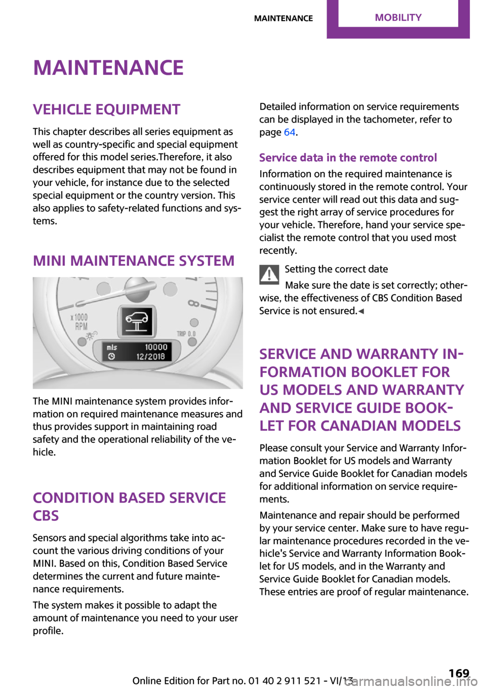
MINI maintenance system
The MINI maintenance system provides infor‐
mation on required maintenance measures and
thus provides support in maintaining road
safety and the operational reliability of the ve‐
hicle.
Condition Based Service
CBS
Sensors and special algorithms take into ac‐
count the various driving conditions of your
MINI. Based on this, Condition Based Service
determines the current and future mainte‐
nance requirements.
The system makes it possible to adapt the
amount of maintenance you need to your user
profile.
Detailed information on service requirements
can be displayed in the tachometer, refer to
page 64.
Service data in the remote control Information on the required maintenance is
continuously stored in the remote control. Your
service center will read out this data and sug‐
gest the right array of service procedures for
your vehicle. Therefore, hand your service spe‐
cialist the remote control that you used most
recently.
Setting the correct date
Make sure the date is set correctly; other‐
wise, the effectiveness of CBS Condition Based
Service is not ensured. ◀
Service and Warranty In‐
formation Booklet for
US models and Warranty
and Service Guide Book‐
let for Canadian models
Please consult your Service and Warranty Infor‐
mation Booklet for US models and Warranty
and Service Guide Booklet for Canadian models
for additional information on service require‐
ments.
Maintenance and repair should be performed
by your service center. Make sure to have regu‐
lar maintenance procedures recorded in the ve‐
hicle's Service and Warranty Information Book‐
let for US models, and in the Warranty and
Service Guide Booklet for Canadian models.
These entries are proof of regular maintenance.Seite 169MaintenanceMobility169
Online Edition for Part no. 01 40 2 911 521 - VI/13
Page 175 of 218
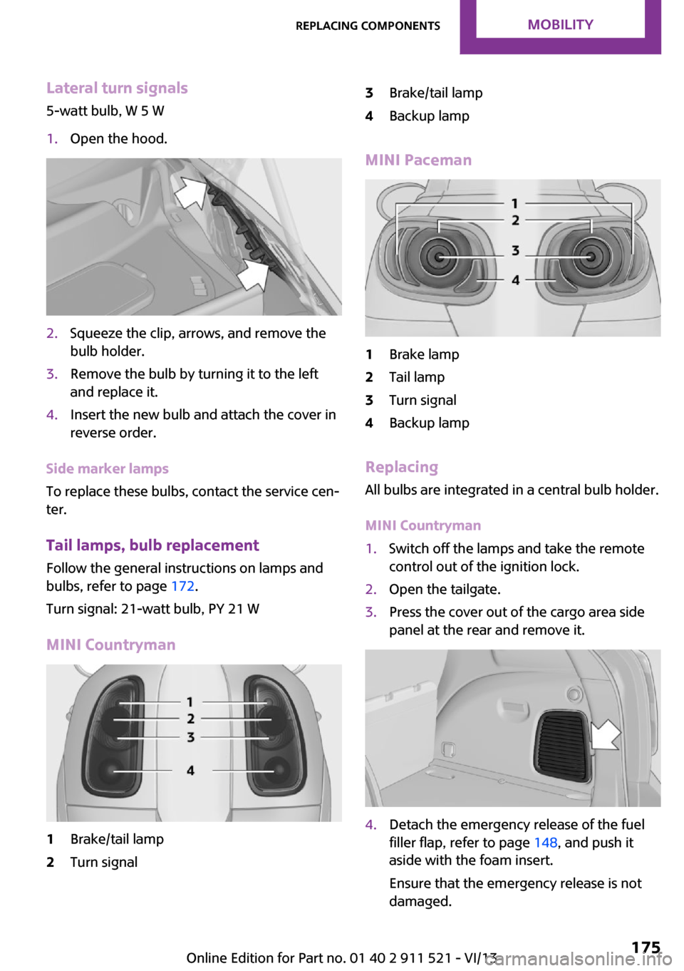
Lateral turn signals
5-watt bulb, W 5 W1.Open the hood.2.Squeeze the clip, arrows, and remove the
bulb holder.3.Remove the bulb by turning it to the left
and replace it.4.Insert the new bulb and attach the cover in
reverse order.
Side marker lamps
To replace these bulbs, contact the service cen‐
ter.
Tail lamps, bulb replacement Follow the general instructions on lamps and
bulbs, refer to page 172.
Turn signal: 21-watt bulb, PY 21 W
MINI Countryman
1Brake/tail lamp2Turn signal3Brake/tail lamp4Backup lamp
MINI Paceman
1Brake lamp2Tail lamp3Turn signal4Backup lamp
Replacing
All bulbs are integrated in a central bulb holder.
MINI Countryman
1.Switch off the lamps and take the remote
control out of the ignition lock.2.Open the tailgate.3.Press the cover out of the cargo area side
panel at the rear and remove it.4.Detach the emergency release of the fuel
filler flap, refer to page 148, and push it
aside with the foam insert.
Ensure that the emergency release is not
damaged.Seite 175Replacing componentsMobility175
Online Edition for Part no. 01 40 2 911 521 - VI/13
Page 176 of 218
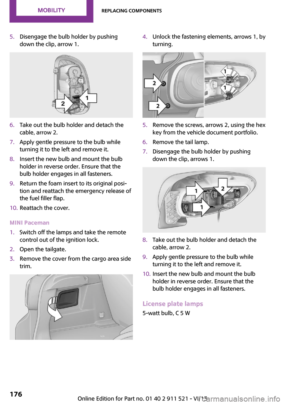
5.Disengage the bulb holder by pushing
down the clip, arrow 1.6.Take out the bulb holder and detach the
cable, arrow 2.7.Apply gentle pressure to the bulb while
turning it to the left and remove it.8.Insert the new bulb and mount the bulb
holder in reverse order. Ensure that the
bulb holder engages in all fasteners.9.Return the foam insert to its original posi‐
tion and reattach the emergency release of
the fuel filler flap.10.Reattach the cover.
MINI Paceman
1.Switch off the lamps and take the remote
control out of the ignition lock.2.Open the tailgate.3.Remove the cover from the cargo area side
trim.4.Unlock the fastening elements, arrows 1, by
turning.5.Remove the screws, arrows 2, using the hex
key from the vehicle document portfolio.6.Remove the tail lamp.7.Disengage the bulb holder by pushing
down the clip, arrows 1.8.Take out the bulb holder and detach the
cable, arrow 2.9.Apply gentle pressure to the bulb while
turning it to the left and remove it.10.Insert the new bulb and mount the bulb
holder in reverse order. Ensure that the
bulb holder engages in all fasteners.
License plate lamps
5-watt bulb, C 5 W
Seite 176MobilityReplacing components176
Online Edition for Part no. 01 40 2 911 521 - VI/13