bulb MINI Paceman 2014 Owner's Manual
[x] Cancel search | Manufacturer: MINI, Model Year: 2014, Model line: Paceman, Model: MINI Paceman 2014Pages: 218, PDF Size: 5.5 MB
Page 52 of 218
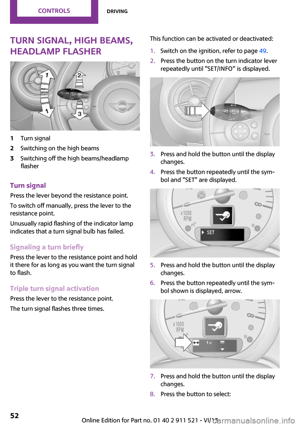
Turn signal, high beams,
headlamp flasher1Turn signal2Switching on the high beams3Switching off the high beams/headlamp
flasher
Turn signal
Press the lever beyond the resistance point.
To switch off manually, press the lever to the
resistance point.
Unusually rapid flashing of the indicator lamp
indicates that a turn signal bulb has failed.
Signaling a turn briefly Press the lever to the resistance point and hold
it there for as long as you want the turn signal
to flash.
Triple turn signal activation Press the lever to the resistance point.
The turn signal flashes three times.
This function can be activated or deactivated:1.Switch on the ignition, refer to page 49.2.Press the button on the turn indicator lever
repeatedly until "SET/INFO" is displayed.3.Press and hold the button until the display
changes.4.Press the button repeatedly until the sym‐
bol and "SET" are displayed.5.Press and hold the button until the display
changes.6.Press the button repeatedly until the sym‐
bol shown is displayed, arrow.7.Press and hold the button until the display
changes.8.Press the button to select:Seite 52ControlsDriving52
Online Edition for Part no. 01 40 2 911 521 - VI/13
Page 172 of 218
Lamp and bulb replace‐
ment
Notes
Lamps and bulbs Lamps and bulbs make an essential contribu‐
tion to vehicle safety. Therefore, exercise cau‐
tion when handling lamps and bulbs.
The manufacturer of the vehicle recommends
that you entrust corresponding procedures to
the service center if you are unfamiliar with
them or they are not described here.
You can obtain a selection of replacement
bulbs at the service center.
Danger of burns
Only change bulbs when they are cool;
otherwise, there is the danger of getting
burned. ◀
Working on the lighting system
When working on the lighting system,
you should always switch off the lights affected
to prevent short circuits.
To avoid possible injury or equipment damage
when replacing bulbs, observe any instructions
provided by the bulb manufacturer. ◀
Do not touch the bulbs
Do not touch the glass of new bulbs with
your bare hands, as even minute amounts of
contamination will burn into the bulb's surface
and reduce its service life.
Use a clean tissue, cloth or something similar,
or hold the bulb by its base. ◀
Caring for the headlamps, refer to page 187.
For bulb replacement that is not described
here, please contact the service center or a
workshop that works according to the repair
procedures of the manufacturer with corre‐
spondingly trained personnel.For checking and adjusting headlamp aim,
please contact your MINI dealer.
Light-emitting diodes LEDs Light-emitting diodes installed behind translu‐
cent lenses serve as the light source for many
of the controls and displays in the vehicle.
These light-emitting diodes, which operate us‐
ing a concept similar to that applied in conven‐
tional lasers, are officially designated as Class 1
light-emitting diodes.
Do not remove the covers
Do not remove the covers, and never
stare into the unfiltered light for several hours;
otherwise, irritation of the retina could result. ◀
Headlamp glass
Condensation can form on the inside of the
headlamps in cool or humid weather. When the
light is switched on, the condensation evapo‐ rates after a short time. The headlamps do notneed to be changed.
If the condensation in the headlamps does not
evaporate after trips with the lights switched
on, and the amount of moisture in the head‐
lamps increases, for example if water droplets
form, have them checked by your service cen‐
ter.
Bi-xenon headlamps These bulbs have a very long life and the likeli‐
hood of failure is very low, provided that they
are not switched on and off excessively. If a
bulb should nevertheless fail, you can continue
driving cautiously with the front fog lamps, pro‐
vided this is permitted by local laws.
Do not perform work/bulb replacement
on xenon headlamps
Have any work on the xenon lighting system,
including bulb replacement, performed only by
a service center.Seite 172MobilityReplacing components172
Online Edition for Part no. 01 40 2 911 521 - VI/13
Page 173 of 218
Due to the high voltage present in the system,
there is the danger of fatal injuries if work is
carried out improperly. ◀
Front lamps, bulb replacement
Halogen low beams and high beams
Bulb H13, 60/55 watt
Wear protective goggles and gloves
Halogen bulbs are pressurized. Therefore,
wear protective goggles and gloves. Otherwise,
there is a danger of injuries if the bulb is acci‐
dentally damaged during replacement. ◀
Attach the cover carefully
When attaching the cover, proceed care‐
fully; otherwise, leaks may occur, causing dam‐
age to the headlamp system. ◀
Access to the bulbs through the engine compartment
Follow the general instructions on lamps and
bulbs, refer to page 172.
Low beam/high beam bulbs can be changed
from the engine compartment.
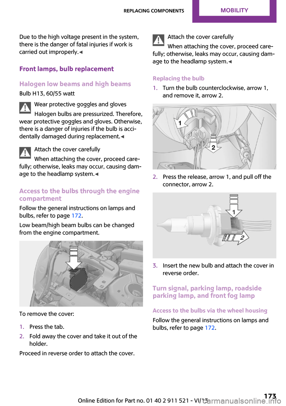
To remove the cover:
1.Press the tab.2.Fold away the cover and take it out of the
holder.
Proceed in reverse order to attach the cover.
Attach the cover carefully
When attaching the cover, proceed care‐
fully; otherwise, leaks may occur, causing dam‐
age to the headlamp system. ◀
Replacing the bulb1.Turn the bulb counterclockwise, arrow 1,
and remove it, arrow 2.2.Press the release, arrow 1, and pull off the
connector, arrow 2.3.Insert the new bulb and attach the cover in
reverse order.
Turn signal, parking lamp, roadside
parking lamp, and front fog lamp
Access to the bulbs via the wheel housing
Follow the general instructions on lamps and
bulbs, refer to page 172.
Seite 173Replacing componentsMobility173
Online Edition for Part no. 01 40 2 911 521 - VI/13
Page 174 of 218
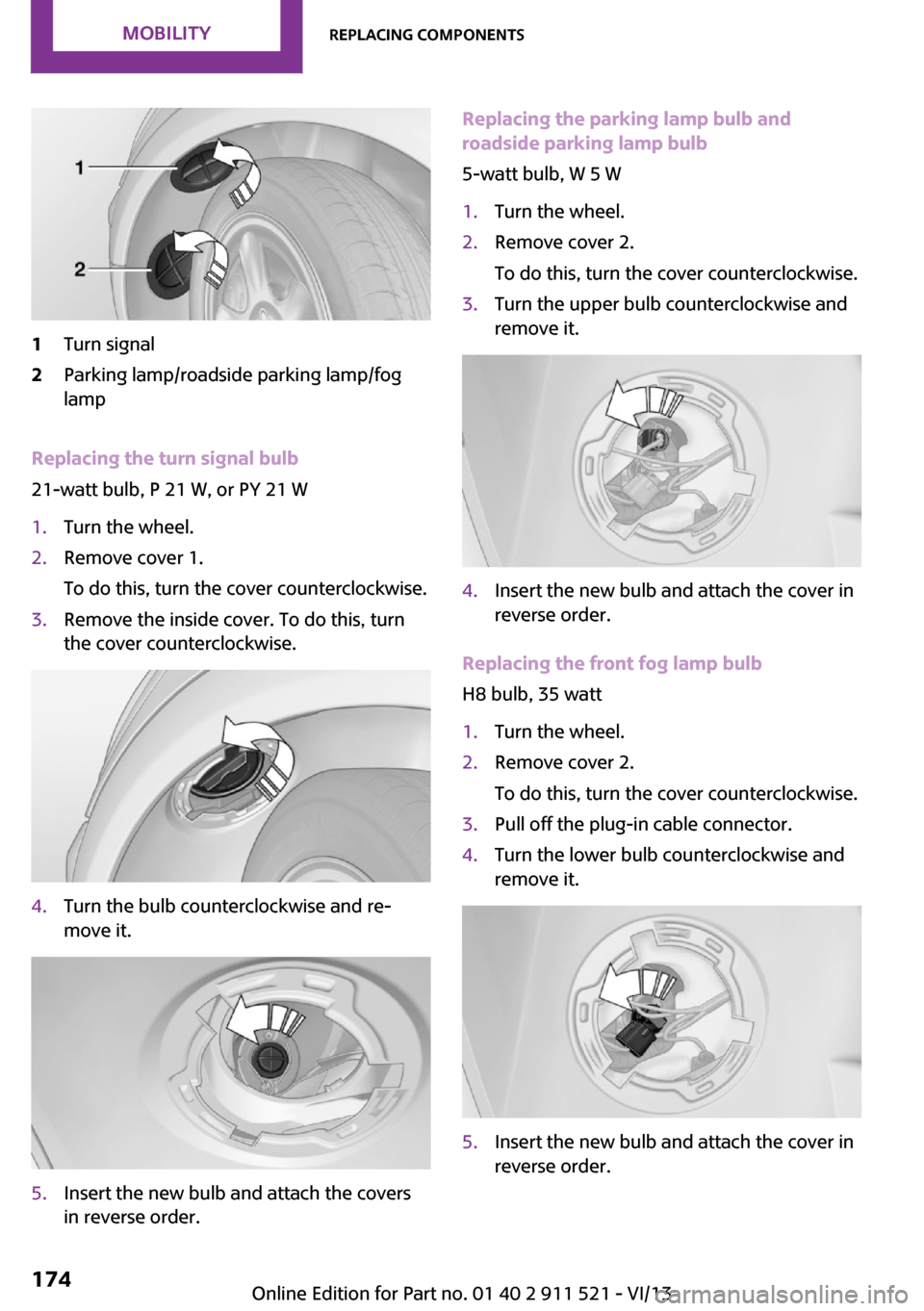
1Turn signal2Parking lamp/roadside parking lamp/fog
lamp
Replacing the turn signal bulb
21-watt bulb, P 21 W, or PY 21 W
1.Turn the wheel.2.Remove cover 1.
To do this, turn the cover counterclockwise.3.Remove the inside cover. To do this, turn
the cover counterclockwise.4.Turn the bulb counterclockwise and re‐
move it.5.Insert the new bulb and attach the covers
in reverse order.Replacing the parking lamp bulb and
roadside parking lamp bulb
5-watt bulb, W 5 W1.Turn the wheel.2.Remove cover 2.
To do this, turn the cover counterclockwise.3.Turn the upper bulb counterclockwise and
remove it.4.Insert the new bulb and attach the cover in
reverse order.
Replacing the front fog lamp bulb
H8 bulb, 35 watt
1.Turn the wheel.2.Remove cover 2.
To do this, turn the cover counterclockwise.3.Pull off the plug-in cable connector.4.Turn the lower bulb counterclockwise and
remove it.5.Insert the new bulb and attach the cover in
reverse order.Seite 174MobilityReplacing components174
Online Edition for Part no. 01 40 2 911 521 - VI/13
Page 175 of 218
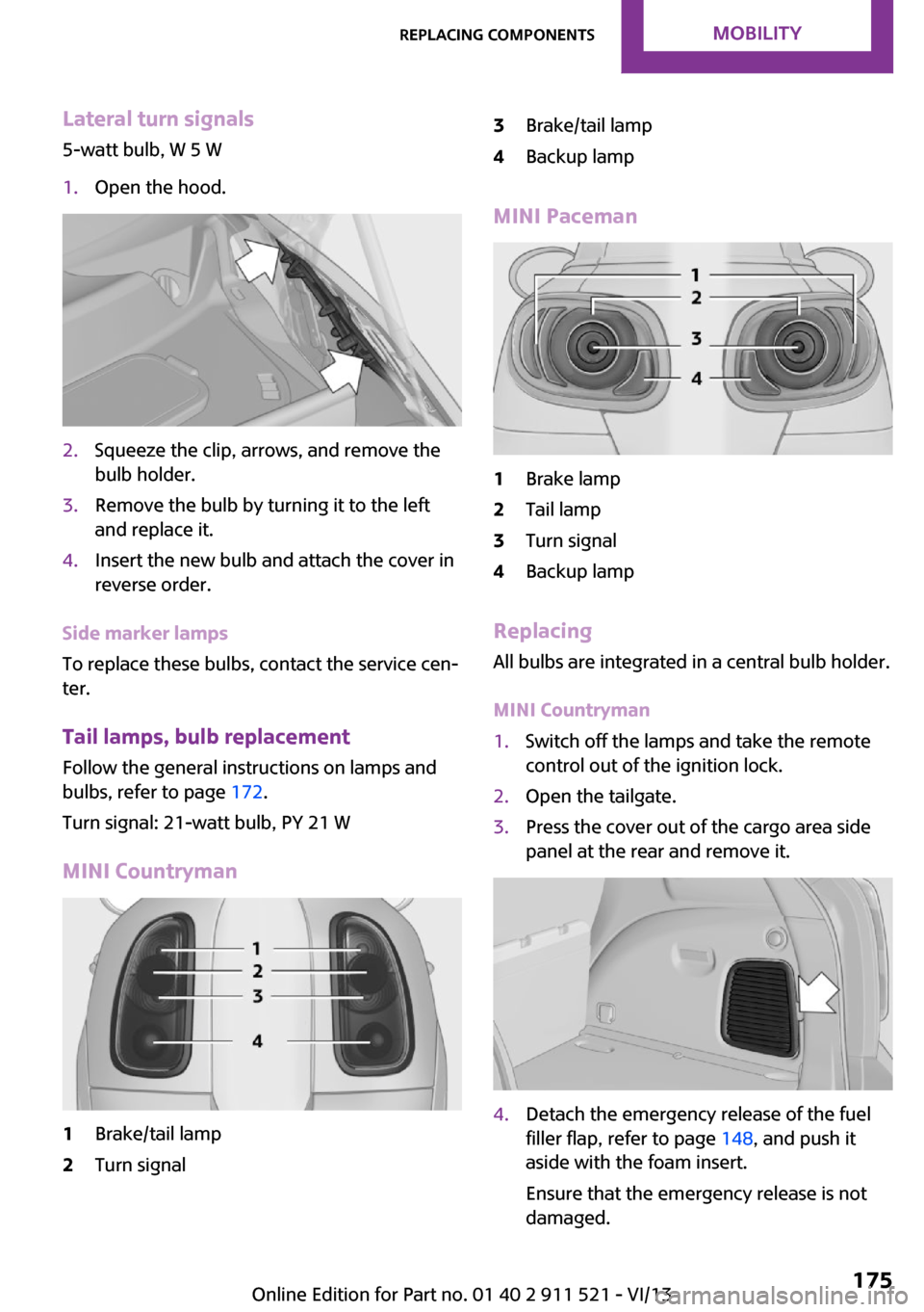
Lateral turn signals
5-watt bulb, W 5 W1.Open the hood.2.Squeeze the clip, arrows, and remove the
bulb holder.3.Remove the bulb by turning it to the left
and replace it.4.Insert the new bulb and attach the cover in
reverse order.
Side marker lamps
To replace these bulbs, contact the service cen‐
ter.
Tail lamps, bulb replacement Follow the general instructions on lamps and
bulbs, refer to page 172.
Turn signal: 21-watt bulb, PY 21 W
MINI Countryman
1Brake/tail lamp2Turn signal3Brake/tail lamp4Backup lamp
MINI Paceman
1Brake lamp2Tail lamp3Turn signal4Backup lamp
Replacing
All bulbs are integrated in a central bulb holder.
MINI Countryman
1.Switch off the lamps and take the remote
control out of the ignition lock.2.Open the tailgate.3.Press the cover out of the cargo area side
panel at the rear and remove it.4.Detach the emergency release of the fuel
filler flap, refer to page 148, and push it
aside with the foam insert.
Ensure that the emergency release is not
damaged.Seite 175Replacing componentsMobility175
Online Edition for Part no. 01 40 2 911 521 - VI/13
Page 176 of 218
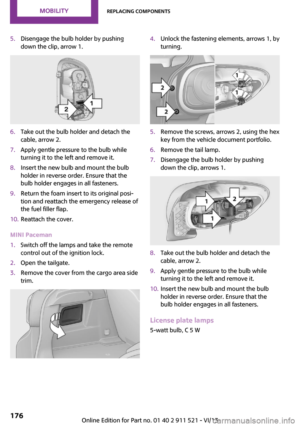
5.Disengage the bulb holder by pushing
down the clip, arrow 1.6.Take out the bulb holder and detach the
cable, arrow 2.7.Apply gentle pressure to the bulb while
turning it to the left and remove it.8.Insert the new bulb and mount the bulb
holder in reverse order. Ensure that the
bulb holder engages in all fasteners.9.Return the foam insert to its original posi‐
tion and reattach the emergency release of
the fuel filler flap.10.Reattach the cover.
MINI Paceman
1.Switch off the lamps and take the remote
control out of the ignition lock.2.Open the tailgate.3.Remove the cover from the cargo area side
trim.4.Unlock the fastening elements, arrows 1, by
turning.5.Remove the screws, arrows 2, using the hex
key from the vehicle document portfolio.6.Remove the tail lamp.7.Disengage the bulb holder by pushing
down the clip, arrows 1.8.Take out the bulb holder and detach the
cable, arrow 2.9.Apply gentle pressure to the bulb while
turning it to the left and remove it.10.Insert the new bulb and mount the bulb
holder in reverse order. Ensure that the
bulb holder engages in all fasteners.
License plate lamps
5-watt bulb, C 5 W
Seite 176MobilityReplacing components176
Online Edition for Part no. 01 40 2 911 521 - VI/13
Page 177 of 218
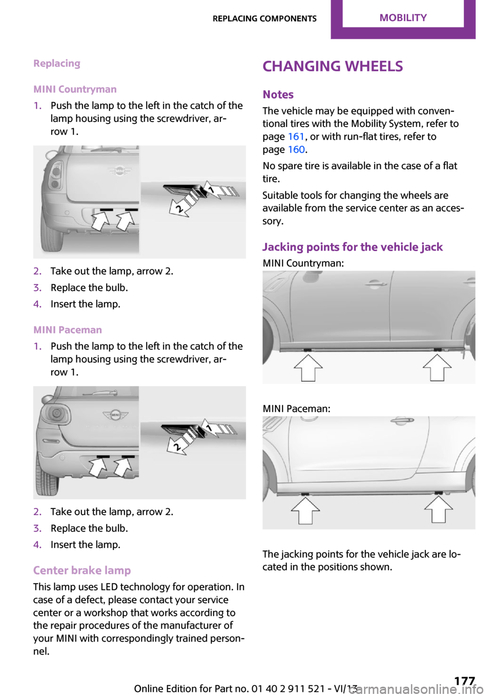
Replacing
MINI Countryman1.Push the lamp to the left in the catch of the
lamp housing using the screwdriver, ar‐
row 1.2.Take out the lamp, arrow 2.3.Replace the bulb.4.Insert the lamp.
MINI Paceman
1.Push the lamp to the left in the catch of the
lamp housing using the screwdriver, ar‐
row 1.2.Take out the lamp, arrow 2.3.Replace the bulb.4.Insert the lamp.
Center brake lamp
This lamp uses LED technology for operation. In
case of a defect, please contact your service
center or a workshop that works according to
the repair procedures of the manufacturer of
your MINI with correspondingly trained person‐
nel.
Changing wheels
Notes
The vehicle may be equipped with conven‐
tional tires with the Mobility System, refer to
page 161, or with run-flat tires, refer to
page 160.
No spare tire is available in the case of a flat
tire.
Suitable tools for changing the wheels are
available from the service center as an acces‐
sory.
Jacking points for the vehicle jack MINI Countryman:
MINI Paceman:
The jacking points for the vehicle jack are lo‐
cated in the positions shown.
Seite 177Replacing componentsMobility177
Online Edition for Part no. 01 40 2 911 521 - VI/13
Page 200 of 218
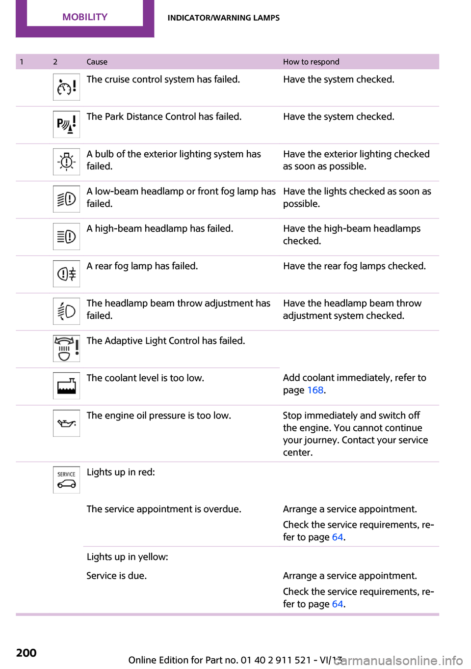
12CauseHow to respondThe cruise control system has failed.Have the system checked.The Park Distance Control has failed.Have the system checked.A bulb of the exterior lighting system has
failed.Have the exterior lighting checked
as soon as possible.A low-beam headlamp or front fog lamp has
failed.Have the lights checked as soon as
possible.A high-beam headlamp has failed.Have the high-beam headlamps
checked.A rear fog lamp has failed.Have the rear fog lamps checked.The headlamp beam throw adjustment has
failed.Have the headlamp beam throw
adjustment system checked.The Adaptive Light Control has failed.The coolant level is too low.Add coolant immediately, refer to
page 168.The engine oil pressure is too low.Stop immediately and switch off
the engine. You cannot continue
your journey. Contact your service
center.Lights up in red:The service appointment is overdue.Arrange a service appointment.
Check the service requirements, re‐
fer to page 64.Lights up in yellow:Service is due.Arrange a service appointment.
Check the service requirements, re‐
fer to page 64.Seite 200MobilityIndicator/warning lamps200
Online Edition for Part no. 01 40 2 911 521 - VI/13
Page 208 of 218
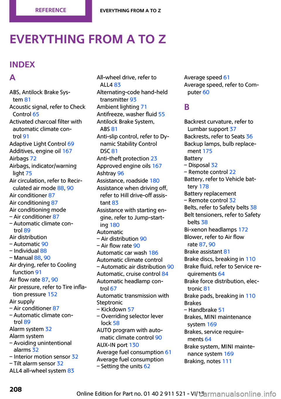
Everything from A to ZIndexA
ABS, Antilock Brake Sys‐ tem 81
Acoustic signal, refer to Check Control 65
Activated charcoal filter with automatic climate con‐
trol 91
Adaptive Light Control 69
Additives, engine oil 167
Airbags 72
Airbags, indicator/warning light 75
Air circulation, refer to Recir‐ culated air mode 88, 90
Air conditioner 87
Air conditioning 87
Air conditioning mode– Air conditioner 87– Automatic climate con‐
trol 89
Air distribution
– Automatic 90– Individual 88– Manual 88, 90
Air drying, refer to Cooling
function 91
Air flow rate 87, 90
Air pressure, refer to Tire infla‐ tion pressure 152
Air supply
– Air conditioner 87– Automatic climate con‐
trol 89
Alarm system 32
Alarm system
– Avoiding unintentional
alarms 32– Interior motion sensor 32– Tilt alarm sensor 32
ALL4 all-wheel system 83
All-wheel drive, refer to
ALL4 83
Alternating-code hand-held transmitter 93
Ambient lighting 71
Antifreeze, washer fluid 55
Antilock Brake System, ABS 81
Anti-slip control, refer to Dy‐ namic Stability Control
DSC 81
Anti-theft protection 23
Approved engine oils 167
Ashtray 96
Assistance, roadside 180
Assistance when driving off, refer to Hill drive-off assis‐
tant 83
Assistance with starting en‐ gine, refer to Jump-start‐
ing 180
Automatic– Air distribution 90– Air flow rate 90
Automatic car wash 186
Automatic climate control
– Automatic air distribution 90
Automatic, cruise control 84
Automatic headlamp con‐ trol 67
Automatic transmission with
Steptronic
– Kickdown 57– Overriding selector lever
lock 58
AUTO program with auto‐
matic climate control 90
AUX-IN port 130
Average fuel consumption 61
Average fuel consumption
– Setting the units 62Average speed 61
Average speed, refer to Com‐ puter 60
B Backrest curvature, refer to Lumbar support 37
Backrests, refer to Seats 36
Backup lamps, bulb replace‐ ment 175
Battery– Disposal 32– Remote control 22
Battery, refer to Vehicle bat‐
tery 178
Battery replacement
– Remote control 32
Belts, refer to Safety belts 38
Belt tensioners, refer to Safety belts 38
Bi-xenon headlamps 172
Blower, refer to Air flow rate 87, 90
Brake assistant 81
Brake discs, breaking in 110
Brake fluid, refer to Service re‐ quirements 64
Brake force distribution, elec‐ tronic 81
Brake pads, breaking in 110
Brakes
– Handbrake 51
Brakes, MINI maintenance
system 169
Brakes, service require‐ ments 64
Brake system, MINI mainte‐ nance system 169
Braking, notes 111
Seite 208ReferenceEverything from A to Z208
Online Edition for Part no. 01 40 2 911 521 - VI/13
Page 211 of 218
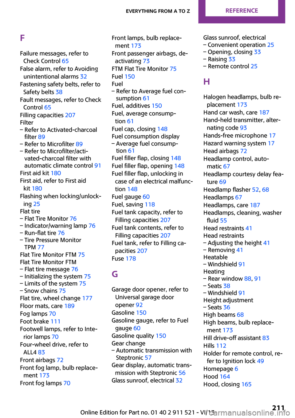
FFailure messages, refer to Check Control 65
False alarm, refer to Avoiding unintentional alarms 32
Fastening safety belts, refer to Safety belts 38
Fault messages, refer to Check Control 65
Filling capacities 207
Filter– Refer to Activated-charcoal
filter 89– Refer to Microfilter 89– Refer to Microfilter/acti‐
vated-charcoal filter with
automatic climate control 91
First aid kit 180
First aid, refer to First aid kit 180
Flashing when locking/unlock‐ ing 25
Flat tire
– Flat Tire Monitor 76– Indicator/warning lamp 76– Run-flat tire 76– Tire Pressure Monitor
TPM 77
Flat Tire Monitor FTM 75
Flat Tire Monitor FTM
– Flat tire message 76– Initializing the system 75– Limits of the system 75– Snow chains 75
Flat tire, wheel change 177
Floor mats, care 189
Fog lamps 70
Foot brake 111
Footwell lamps, refer to Inte‐ rior lamps 70
Four-wheel drive, refer to ALL4 83
Front airbags 72
Front fog lamp, bulb replace‐ ment 173
Front fog lamps 70
Front lamps, bulb replace‐
ment 173
Front passenger airbags, de‐ activating 73
FTM Flat Tire Monitor 75
Fuel 150
Fuel– Refer to Average fuel con‐
sumption 61
Fuel, additives 150
Fuel, average consump‐ tion 61
Fuel cap, closing 148
Fuel consumption display
– Average fuel consump‐
tion 61
Fuel filler flap, closing 148
Fuel filler flap, opening 148
Fuel filler flap, unlocking in case of an electrical malfunc‐
tion 148
Fuel gauge 60
Fuel, saving 118
Fuel tank capacity, refer to Filling capacities 207
Fuel tank contents, refer to Filling capacities 207
Fuel tank, refer to Filling ca‐ pacities 207
Fuse 178
G Garage door opener, refer to Universal garage door
opener 92
Gasoline 150
Gasoline gauge, refer to Fuel gauge 60
Gasoline quality 150
Gear change
– Automatic transmission with
Steptronic 57
Gear display, automatic trans‐
mission with Steptronic 56
Glass sunroof, electrical 32
Glass sunroof, electrical– Convenient operation 25– Opening, closing 33– Raising 33– Remote control 25
H
Halogen headlamps, bulb re‐ placement 173
Hand car wash, care 187
Hand-held transmitter, alter‐ nating code 93
Hands-free microphone 17
Hazard warning system 17
Head airbags 72
Headlamp control, auto‐ matic 67
Headlamp courtesy delay fea‐ ture 69
Headlamp flasher 52, 68
Headlamps 67
Headlamps, care 187
Headlamps, cleaning, washer fluid 55
Head restraints 41
Head restraints
– Adjusting the height 41– Removing 41
Heatable
– Windshield 91
Heating
– Rear window 88, 91– Seats 38– Windshield 91
Height adjustment
– Seats 36
High beams 68
High beams, bulb replace‐ ment 173
Hill drive-off assistant 83
Hills 112
Holder for remote control, re‐ fer to Ignition lock 49
Homepage 6
Hood 164
Hood, closing 165
Seite 211Everything from A to ZReference211
Online Edition for Part no. 01 40 2 911 521 - VI/13