fuel light MINI Paceman 2014 Owner's Manual
[x] Cancel search | Manufacturer: MINI, Model Year: 2014, Model line: Paceman, Model: MINI Paceman 2014Pages: 218, PDF Size: 5.5 MB
Page 16 of 218
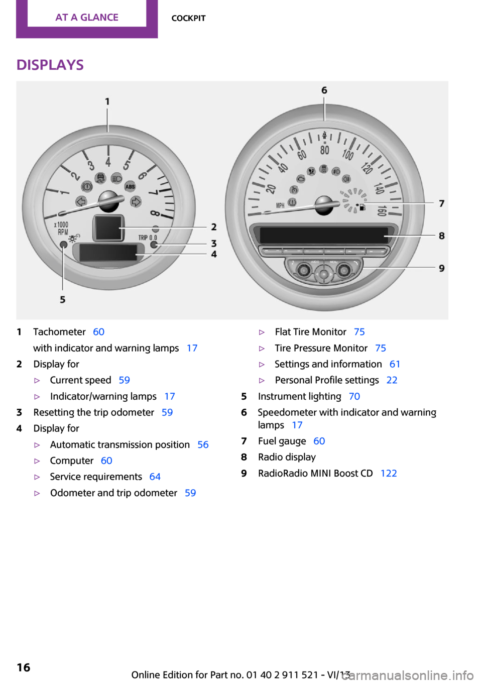
Displays1Tachometer 60
with indicator and warning lamps 172Display for▷Current speed 59▷Indicator/warning lamps 173Resetting the trip odometer 594Display for▷Automatic transmission position 56▷Computer 60▷Service requirements 64▷Odometer and trip odometer 59▷Flat Tire Monitor 75▷Tire Pressure Monitor 75▷Settings and information 61▷Personal Profile settings 225Instrument lighting 706Speedometer with indicator and warning
lamps 177Fuel gauge 608Radio display9RadioRadio MINI Boost CD 122Seite 16At a glanceCockpit16
Online Edition for Part no. 01 40 2 911 521 - VI/13
Page 23 of 218
stored with it are called up and imple‐
mented.▷Your personal settings will be recognized
and called up again even if the vehicle has
been used in the meantime by someone
else with another remote control.▷The individual settings are stored for no
more than three remote controls.
Personal Profile settings
The following functions and settings can be
stored in a profile.
More information on the settings can be found
under:
▷Response of the central locking system
when the car is being unlocked, refer to
page 24.▷Automatic locking of the vehicle, refer to
page 28.▷Triple turn signal activation, refer to
page 52.▷Settings for the displays in the speedometer
and tachometer:▷12h/24h clock format, refer to
page 62.▷Date format, refer to page 62.▷Units of measure for fuel consumption,
distance covered/remaining distances,
and temperature, refer to page 62.▷Light settings:▷Headlamp courtesy delay feature, refer
to page 69.▷Daytime running lights, refer to
page 68.▷Automatic climate control, refer to
page 89: AUTO program, activating/deac‐
tivating the cooling function, setting the
temperature, air volume, and air distribu‐
tion.▷Entertainment:▷Last entertainment source.▷Radio MINI Boost CD:
Tone settings, refer to page 124.
Volume, refer to page 124.
Central locking system
The concept
The central locking system becomes active
when the driver's door is closed.
The system simultaneously engages and re‐
leases the locks on the following:
▷Doors.▷Tailgate.▷Fuel filler flap.
Operating from the outside
▷Via the remote control.▷Via the door lock.▷In cars with Comfort Access, via the door
handles on the driver's and front passenger
sides.
The following takes place simultaneously when
locking/unlocking the vehicle via the remote
control:
▷Depending on the vehicle equipment, the
anti-theft protection is switched on and off
as well. The anti-theft protection makes it
impossible to unlock the doors using the
lock buttons or door handles.▷The welcome lamps, interior lamps, and
ambient lighting are switched on and off.▷The alarm system is armed or disarmed, re‐
fer to page 32.
Operating from the inside
Via the switch/button for the central locking
system, refer to page 27.
In an accident of the necessary severity, the
central locking system unlocks automatically.
Seite 23Opening and closingControls23
Online Edition for Part no. 01 40 2 911 521 - VI/13
Page 60 of 218
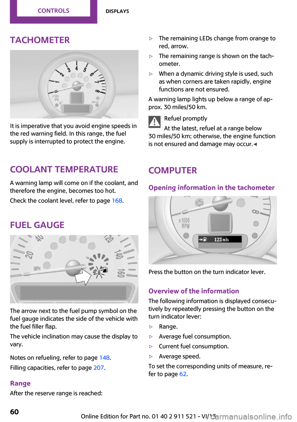
Tachometer
It is imperative that you avoid engine speeds in
the red warning field. In this range, the fuel
supply is interrupted to protect the engine.
Coolant temperature A warning lamp will come on if the coolant, and
therefore the engine, becomes too hot.
Check the coolant level, refer to page 168.
Fuel gauge
The arrow next to the fuel pump symbol on the
fuel gauge indicates the side of the vehicle with
the fuel filler flap.
The vehicle inclination may cause the display to
vary.
Notes on refueling, refer to page 148.
Filling capacities, refer to page 207.
Range After the reserve range is reached:
▷The remaining LEDs change from orange to
red, arrow.▷The remaining range is shown on the tach‐
ometer.▷When a dynamic driving style is used, such
as when corners are taken rapidly, engine
functions are not ensured.
A warning lamp lights up below a range of ap‐
prox. 30 miles/50 km.
Refuel promptly
At the latest, refuel at a range below
30 miles/50 km; otherwise, the engine function
is not ensured and damage may occur. ◀
Computer
Opening information in the tachometer
Press the button on the turn indicator lever.
Overview of the information
The following information is displayed consecu‐
tively by repeatedly pressing the button on the
turn indicator lever:
▷Range.▷Average fuel consumption.▷Current fuel consumption.▷Average speed.
To set the corresponding units of measure, re‐
fer to page 62.
Seite 60ControlsDisplays60
Online Edition for Part no. 01 40 2 911 521 - VI/13
Page 80 of 218

Final tire failure
Vibrations or loud noises while driving
can indicate the final failure of the tire. Reduce
speed and stop; otherwise, pieces of the tire
could come loose and cause an accident. Do
not continue driving, and contact your service
center. ◀
Malfunction The small warning lamp flashes in yel‐
low and then lights up continuously; the larger warning lamp comes on in yel‐
low.
No flat tire can be detected.
Display in the following situations:▷A wheel without TPM electronics is
mounted:
Have the system checked by the service
center if necessary.▷Malfunction:
Have the system checked.▷TPM could not be fully reset; reset the sys‐
tem again.
The small warning lamp flashes in yel‐
low and then lights up continuously; the
larger warning lamp comes on in yel‐
low.
No flat tire can be detected.
Display in the following situation:
▷Disturbance by other systems or devices
with the same radio frequency
After leaving the area of the disturbance,
the system automatically becomes active
again.
Declaration according to NHTSA/FMVSS
138 Tire Pressure Monitoring Systems
Each tire, including the spare (if provided)
should be checked monthly when cold and in‐
flated to the inflation pressure recommended
by the vehicle manufacturer on the vehicle
placard or tire inflation pressure label (If your
vehicle has tires of a different size than the size
indicated on the vehicle placard or tire inflation
pressure label, you should determine the
proper tire inflation pressure for those tires.).
As an added safety feature, your vehicle has
been equipped with a tire pressure monitoring
system (TPMS) that illuminates a low tire pres‐
sure telltale when one or more of your tires is
significantly under-inflated. Accordingly, when
the low tire pressure telltale illuminates, you
should stop and check your tires as soon as
possible, and inflate them to the proper pres‐
sure. Driving on a significantly under-inflated
tire causes the tire to overheat and can lead to
tire failure. Under-inflation also reduces fuel ef‐
ficiency and tire tread life, and may affect the
vehicle's handling and stopping ability.
Please note that the TPMS is not a substitute for
proper tire maintenance, and it is the driver's
responsibility to maintain correct tire pressure,
even if under-inflation has not reached the
level to trigger illumination of the TPMS low tire
pressure telltale.
Your vehicle has also been equipped with a
TPMS malfunction indicator to indicate when
the system is not operating properly. The TPMS
malfunction indicator is combined with the low
tire pressure telltale. When the system detects
a malfunction, the telltale will flash for approxi‐
mately one minute and then remain continu‐
ously illuminated. This sequence will continue
upon subsequent vehicle startups as long as
the malfunction exists. When the malfunction
indicator is illuminated, the system may not be
able to detect or signal low tire pressure as in‐
tended. TPMS malfunctions may occur for a va‐
riety of reasons, including the installation of re‐
placement or alternate tires or wheels on the
vehicle that prevent the TPMS from functioning
properly. Always check the TPMS malfunction
telltale after replacing one or more tires or
wheels on your vehicle to ensure that the re‐
placement or alternate tires and wheels allow
the TPMS to continue to function properly.Seite 80ControlsSafety80
Online Edition for Part no. 01 40 2 911 521 - VI/13
Page 118 of 218
Saving fuelVehicle equipment
This chapter describes all series equipment as
well as country-specific and special equipment
offered for this model series.Therefore, it also
describes equipment that may not be found in
your vehicle, for instance due to the selected
special equipment or the country version. This
also applies to safety-related functions and sys‐
tems.
General information Your vehicle contains advanced technology for
the reduction of fuel consumption and emis‐
sions.
Fuel consumption depends on a number of dif‐
ferent factors. The implementation of certain
measures, driving style and regular mainte‐ nance can have an influence on fuel consump‐
tion and on the environmental impact.
Remove unnecessary cargo Additional weight increases fuel consumption.
Remove attached parts following use Remove unneeded auxiliary mirrors, roof or
rear luggage racks after use.
Attached parts on the vehicle impair the aero‐
dynamics and increase the fuel consumption.
Close both windows Open windows causes higher air resistance and
thus increases fuel consumption.
Check the tire inflation pressure
regularly
Check and, if necessary, correct the tire infla‐
tion pressure, refer to page 152, at least twice
a month and before starting on a long trip.Low tire inflation pressure increases rolling re‐
sistance and thus raises fuel consumption and
tire wear.
Drive away without delayDo not wait for the engine to warm-up while
the vehicle remains stationary. Start driving
right away, but at moderate engine speeds.
This is the fastest way for the cold engine to
reach its operating temperature.
Look well ahead when driving Avoid unnecessary acceleration and braking. To
achieve this, maintain a suitable distance to the
vehicle driving ahead of you.
Driving smoothly and looking ahead reduces
fuel consumption.
Avoid high engine speeds Use 1st gear to get the vehicle in motion. Be‐
ginning with 2nd gear, accelerate rapidly. When
accelerating, shift up before reaching high en‐
gine speeds.
When you reach the desired speed, shift into
the highest applicable gear and drive with the
engine speed as low as possible and at a con‐
stant speed.
As a rule: driving at low engine speeds lowers
fuel consumption and reduces wear.
Use coasting conditions
When approaching a red light, take your foot
off the accelerator and coast to a halt in the
highest applicable gear.
On a downhill slope, take your foot off the ac‐
celerator and coast in a suitable gear.
The flow of fuel is interrupted while coasting.Seite 118Driving tipsSaving fuel118
Online Edition for Part no. 01 40 2 911 521 - VI/13
Page 119 of 218
Switch off the engine during longer
stops
Switch off the engine during longer stops, e.g.,
at traffic lights, railroad crossings or in traffic
congestion.
Fuel savings are already achieved after the en‐
gine is turned off for as little as 4 seconds.
Automatic Engine Start/Stop Function
The Automatic Engine Start/Stop Function auto‐
matically switches the engine off during a stop.
If the engine is stopped and then started again,
fuel consumption and emissions drop com‐
pared to an engine that runs permanently.
Stopping the engine even for just a few sec‐
onds can result in savings.
In addition, fuel consumption depends on other
factors as well, such as driving style, road con‐
ditions, maintenance, and environmental fac‐
tors.
Switch off any functions that are not currently needed
Functions such as seat heating and the rear
window defroster require a lot of energy and
consume additional fuel, especially in city and
stop-and-go traffic.
Therefore, switch off these functions if they are
not actually needed.
Have maintenance carried out
Have vehicles maintained regularly to achieve
optimal vehicle economy and operating life.
Have the maintenance carried out by the serv‐
ice center.
Please also note the MINI maintenance system,
refer to page 169.Seite 119Saving fuelDriving tips119
Online Edition for Part no. 01 40 2 911 521 - VI/13
Page 125 of 218
▷"LANG": select the language of the dis‐
play texts.▷"CONSMP": change the unit of measure
for the average fuel consumption.▷"TEMP": change the unit of measure for
the external temperature.5.Highlight the desired menu item and press
the button.6.Create the desired setting.
Computer
The following vehicle information can be call up
via the computer:
▷Average fuel consumption▷Average speed▷Range
Displaying information
1.Switch on the radio ready state or the igni‐
tion.2. Press the button.3."COMP"
Average fuel consumption
The average fuel consumption is calculated for
the time during which the engine is running.
To start calculation of the average fuel con‐
sumption:
1."CONSMP"2."RESET"
The previous display is set to zero and the sys‐
tem begins recalculating the average fuel con‐
sumption.
Average speed
The average speed is calculated for the time
during which the engine is running.
To start calculation of the average speed:
1."SPEED"2."RESET"
Estimated range
"RANGE"
The display shows the estimated distance that
can be still be driven on the remaining fuel,
taking into consideration the driving style over
the last 18 miles/30 km.
Radio
Listening to the radio
The radio is designed for reception in the FM
and AM wavebands.
1.Switch on the radio, refer to page 123.2. Press this button if necessary.3."TUNER"4."FM" or"AM"
Press the corresponding button repeatedly
until the desired waveband is displayed.▷FM: FM1, FM2, FMA▷AM: AM, AMA
Selecting a station
The setting is stored for the remote control cur‐
rently in use.
Next station
Press the button.
The next station with reception is selected.
Selecting the station manually by
frequency
1. Press the button.2.▷Press the respective function button to
set the desired frequency.▷Turn the right knob until the desired
frequency is set.Seite 125Radio MINI Boost CDEntertainment125
Online Edition for Part no. 01 40 2 911 521 - VI/13
Page 160 of 218
Maximum speed of winter tires
If the maximum speed of the vehicle is higher
than the permissible speed for the winter tires,
then display a corresponding sign in the field of
vision. You can obtain this sign from the tire
specialist or from your service center.
Maximum speed for winter tires
Do not exceed the maximum speed for
the winter tires; otherwise, tire damage and ac‐
cidents can occur. ◀
Run-flat tires When mounting new tires or changing fromsummer to winter tires or vice versa, use run-
flat tires for your own safety. Also, a compact
wheel is not available in case of a flat tire. Your
service center will be glad to advise you.
Rotating wheels between axles
Different wear patterns occur on the front and
rear axles, depending on the individual condi‐
tions of use.
To ensure even wear on the tires, the wheels
can be rotated between the axles. Your service
center will be glad to advise you.
After changing the tires, check the tire inflation
pressure and correct it if necessary.
Storage Store wheels and tires in a cool, dry place with
as little exposure to light as possible.
Always protect tires against all contact with oil,
grease and fuels.
Do not exceed the maximum tire inflation pres‐
sure indicated on the side wall of the tire.Run-flat tires
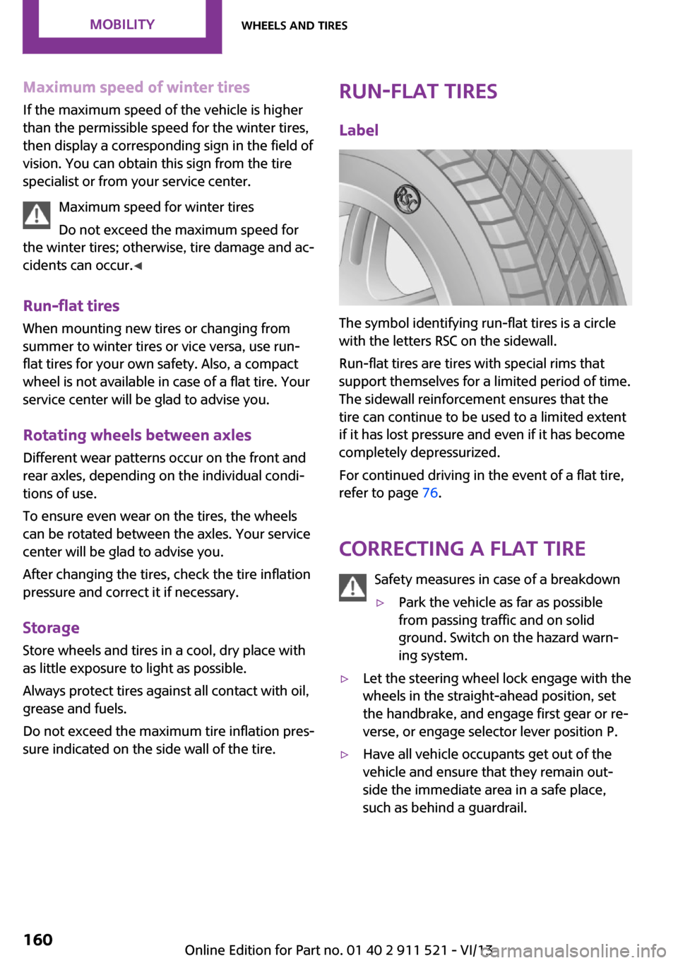
Label
The symbol identifying run-flat tires is a circle
with the letters RSC on the sidewall.
Run-flat tires are tires with special rims that
support themselves for a limited period of time.
The sidewall reinforcement ensures that the
tire can continue to be used to a limited extent
if it has lost pressure and even if it has become
completely depressurized.
For continued driving in the event of a flat tire,
refer to page 76.
Correcting a flat tire Safety measures in case of a breakdown
▷Park the vehicle as far as possible
from passing traffic and on solid
ground. Switch on the hazard warn‐
ing system.▷Let the steering wheel lock engage with the
wheels in the straight-ahead position, set
the handbrake, and engage first gear or re‐
verse, or engage selector lever position P.▷Have all vehicle occupants get out of the
vehicle and ensure that they remain out‐
side the immediate area in a safe place,
such as behind a guardrail.Seite 160MobilityWheels and tires160
Online Edition for Part no. 01 40 2 911 521 - VI/13
Page 170 of 218
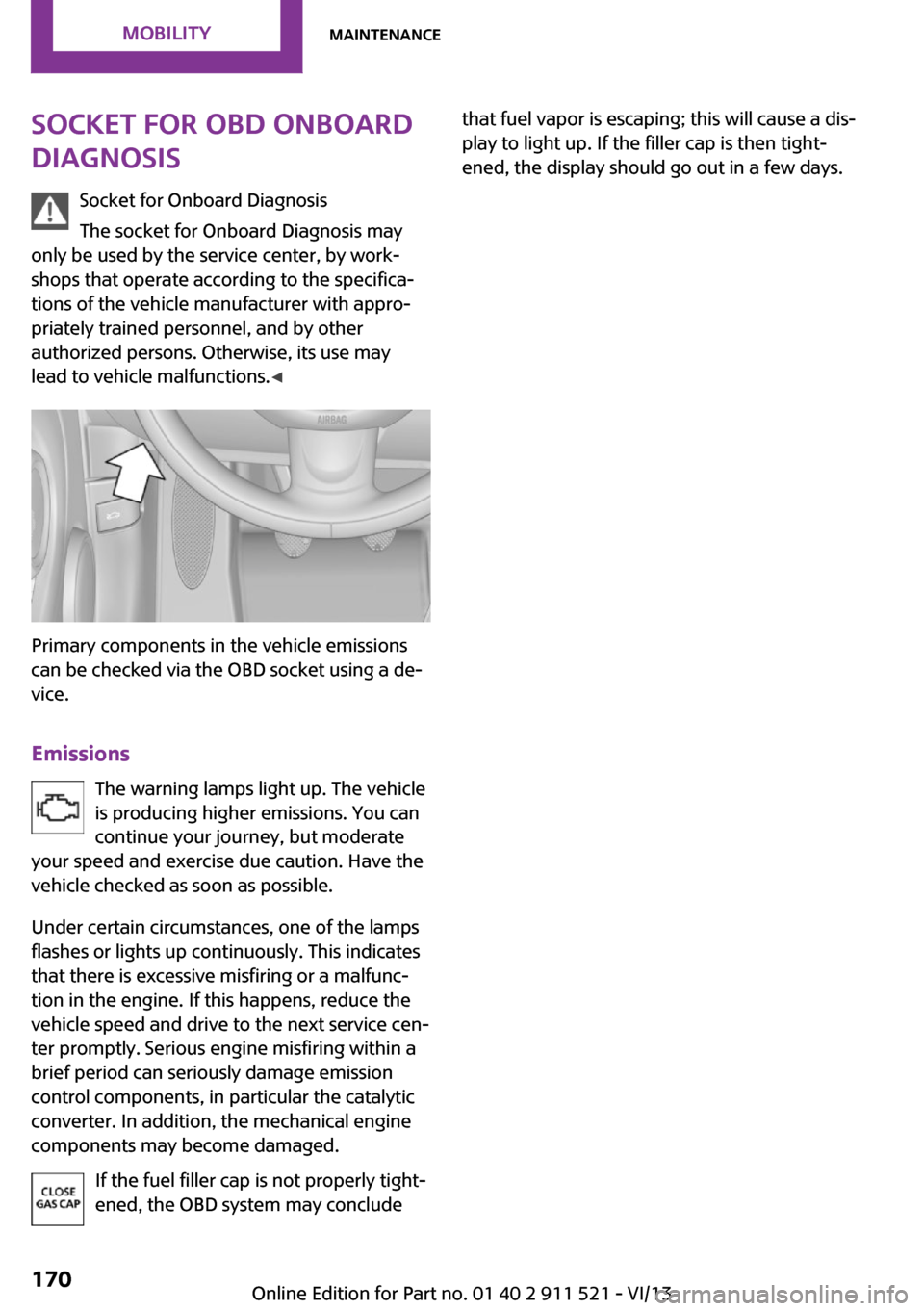
Socket for OBD Onboard
Diagnosis
Socket for Onboard Diagnosis
The socket for Onboard Diagnosis may
only be used by the service center, by work‐
shops that operate according to the specifica‐
tions of the vehicle manufacturer with appro‐
priately trained personnel, and by other
authorized persons. Otherwise, its use may
lead to vehicle malfunctions. ◀
Primary components in the vehicle emissions
can be checked via the OBD socket using a de‐
vice.
Emissions The warning lamps light up. The vehicle
is producing higher emissions. You can
continue your journey, but moderate
your speed and exercise due caution. Have the
vehicle checked as soon as possible.
Under certain circumstances, one of the lamps
flashes or lights up continuously. This indicates
that there is excessive misfiring or a malfunc‐
tion in the engine. If this happens, reduce the
vehicle speed and drive to the next service cen‐
ter promptly. Serious engine misfiring within a
brief period can seriously damage emission
control components, in particular the catalytic
converter. In addition, the mechanical engine
components may become damaged.
If the fuel filler cap is not properly tight‐
ened, the OBD system may conclude
that fuel vapor is escaping; this will cause a dis‐
play to light up. If the filler cap is then tight‐
ened, the display should go out in a few days.Seite 170MobilityMaintenance170
Online Edition for Part no. 01 40 2 911 521 - VI/13
Page 188 of 218

Vehicle paint
Regular care contributes to vehicle value reten‐
tion and protects the paintwork against the
long-term effects of paint-damaging substan‐
ces.
Environmental influences in areas with higher
air pollution or natural contaminants, such as
tree resin or pollen, can have an impact on the
vehicle paint. Therefore, it is important to tailor
the frequency and extent of your car care to
these influences.
Immediately remove especially aggressive sub‐
stances, such as spilled fuel, oil, grease, or bird
droppings, to prevent damage to the paint‐
work.
Correcting paint damage
Depending on the severity of the damage, re‐
pair stone impact damage or scratches imme‐
diately to prevent rust formation.
The manufacturer recommends having paint
damage corrected with a professional repair
paint job according to factory specifications us‐
ing original MINI paint materials.
Preservation
Preservation is needed when water no longer
beads off of the clean paint surfaces. Only use
paint preservation products that contain car‐
nauba or synthetic waxes.
Leather care The leather processed by the manufacturer is a
high quality natural product. Light graininess is
a typical feature of natural leather.
Particles of dust and road grime chafe in pores
and folds, and lead to increased wear and pre‐
mature degradation of the leather surface.
Therefore, remove dust from the leather regu‐
larly, using a cloth or vacuum cleaner.
Make especially sure that light-colored leather
is cleaned regularly as it is more susceptible to
soiling.Twice a year, treat the leather with a leather lo‐
tion as dirt and grease will attack the protective
layer of the leather.
Upholstery material care
Vacuum regularly with a vacuum cleaner to re‐
move superficial soiling.
In case of heavy soiling, e.g., beverage stains,
use a soft sponge or lint-free microfiber cloth in
combination with a suitable interior cleaner.
Follow the instructions on the container.
Clean the upholstery material down to the
seams using large sweeping motions. Avoid
rubbing the material vigorously.
Damage from Velcro® fasteners
Open Velcro® fasteners on pants or other
articles of clothing can damage the seat covers.
Ensure that any Velcro® fasteners are closed. ◀
Caring for special components Interior plastic parts These include:▷Imitation leather surfaces▷Lamp lenses▷Indicator covers▷Matte components
Clean with water and a solvent-free plastic
cleaner if necessary.
Do not use cleansers that contain alcohol
or solvents
Do not use cleansers that contain alcohol or
solvents, such as lacquer thinners, heavy-duty
grease removers, fuel, or such; this could lead
to surface damage. ◀
Rubber seals Only treat with water or a rubber care product.
When cleaning rubber seals, do not use silicone
sprays or other care products containing sili‐
cone; otherwise, noise and damage may result.
Seite 188MobilityCare188
Online Edition for Part no. 01 40 2 911 521 - VI/13