service indicator MINI Paceman 2014 Owner's Manual
[x] Cancel search | Manufacturer: MINI, Model Year: 2014, Model line: Paceman, Model: MINI Paceman 2014Pages: 218, PDF Size: 5.5 MB
Page 16 of 218
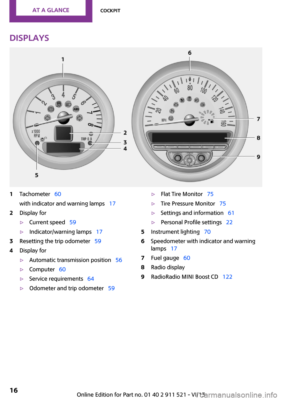
Displays1Tachometer 60
with indicator and warning lamps 172Display for▷Current speed 59▷Indicator/warning lamps 173Resetting the trip odometer 594Display for▷Automatic transmission position 56▷Computer 60▷Service requirements 64▷Odometer and trip odometer 59▷Flat Tire Monitor 75▷Tire Pressure Monitor 75▷Settings and information 61▷Personal Profile settings 225Instrument lighting 706Speedometer with indicator and warning
lamps 177Fuel gauge 608Radio display9RadioRadio MINI Boost CD 122Seite 16At a glanceCockpit16
Online Edition for Part no. 01 40 2 911 521 - VI/13
Page 41 of 218
Safety belt reminder for driver's seat
and front passenger seat
The indicator lamps light up and a sig‐
nal sounds. Check whether the safety
belt has been fastened correctly.
Damage to safety belts In the case of strain caused by accidents or
damage:
Have the safety belts, including the safety belt
tensioners, replaced and have the belt anchors
checked.
Checking and replacing safety belts
Have the work performed only by your
service center; otherwise, it cannot be ensured
that this safety feature will function properly. ◀
Head restraints Correctly set head restraintA correctly adjusted head restraint reduces the
risk of spinal injury in the event of an accident.
Adjusting the head restraint
Correctly adjust the head restraints of all
occupied seats; otherwise, there is an increased
risk of injury in an accident. ◀
Height
Adjust the head restraint so that its center is
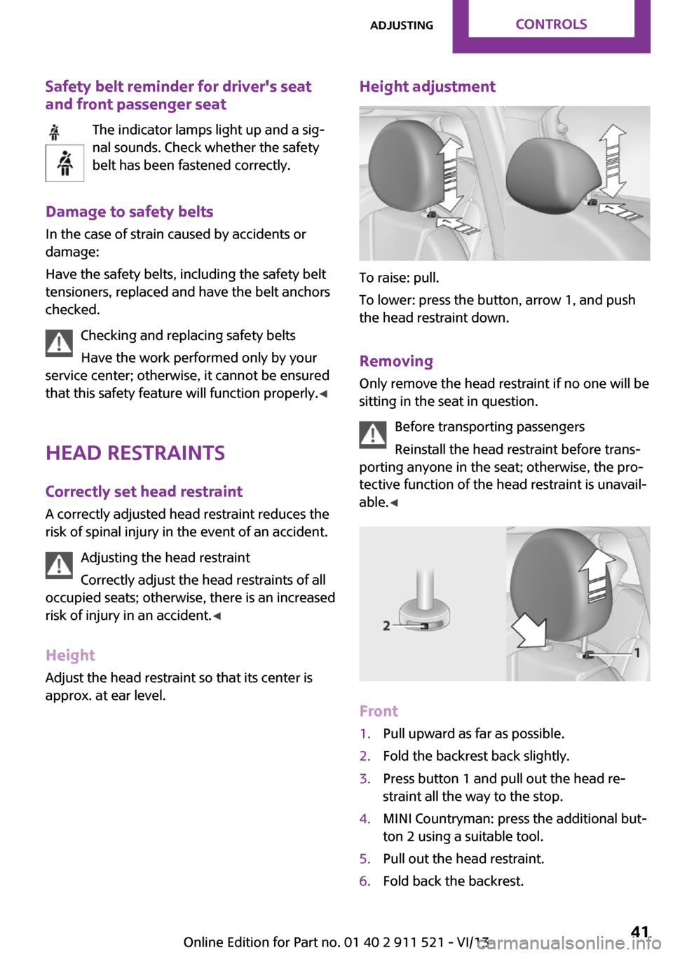
approx. at ear level.Height adjustment
To raise: pull.
To lower: press the button, arrow 1, and push
the head restraint down.
Removing
Only remove the head restraint if no one will be
sitting in the seat in question.
Before transporting passengers
Reinstall the head restraint before trans‐
porting anyone in the seat; otherwise, the pro‐
tective function of the head restraint is unavail‐
able. ◀
Front
1.Pull upward as far as possible.2.Fold the backrest back slightly.3.Press button 1 and pull out the head re‐
straint all the way to the stop.4.MINI Countryman: press the additional but‐
ton 2 using a suitable tool.5.Pull out the head restraint.6.Fold back the backrest.Seite 41AdjustingControls41
Online Edition for Part no. 01 40 2 911 521 - VI/13
Page 61 of 218
Information in detail
Range
Displays the estimated cruising range available
with the remaining fuel.
It is calculated based on your driving style over
the last 18 miles/30 km.
Average fuel consumption This is calculated for the period during which
the engine is running.
To reset the average consumption: press the
button on the turn indicator lever for ap‐
prox. 2 seconds.
Current fuel consumption Displays the current fuel consumption. You can
check whether you are currently driving in an
efficient and environmentally-friendly manner.
Average speed Periods in which the vehicle was parked and
the engine was switched off manually are not
included in the average speed calculations.
To reset the average speed: press the button
on the turn indicator lever for approx. 2 sec‐
onds.
Radio MINI Boost CD: displays on the
radio
Some computer functions can also be shown
on the radio display, refer to page 125.
Settings and information Operating conceptSome settings and information can only be cre‐
ated or opened while the ignition is switched
on, the vehicle is standing, and the doors are
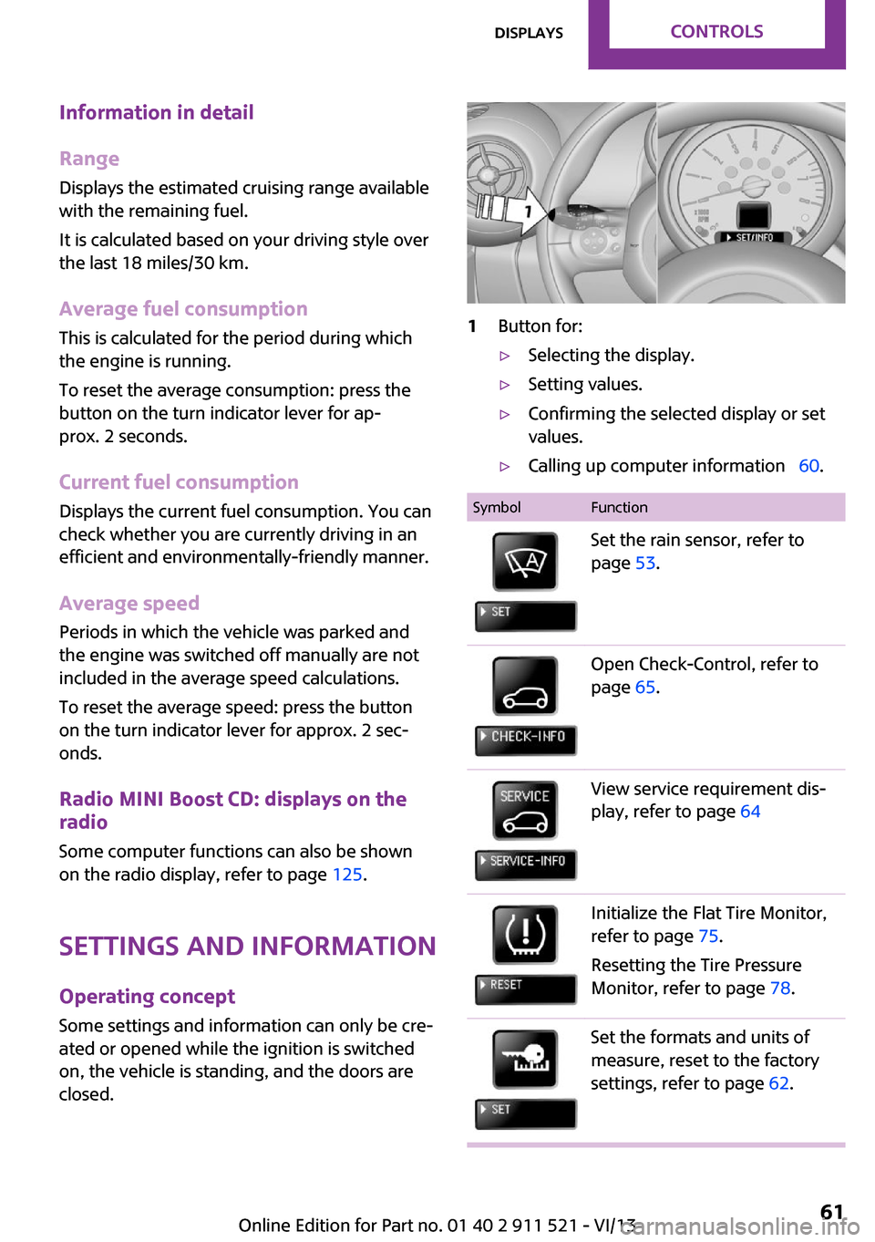
closed.1Button for:▷Selecting the display.▷Setting values.▷Confirming the selected display or set
values.▷Calling up computer information 60.SymbolFunctionSet the rain sensor, refer to
page 53.Open Check-Control, refer to
page 65.View service requirement dis‐
play, refer to page 64Initialize the Flat Tire Monitor,
refer to page 75.
Resetting the Tire Pressure
Monitor, refer to page 78.Set the formats and units of
measure, reset to the factory
settings, refer to page 62.Seite 61DisplaysControls61
Online Edition for Part no. 01 40 2 911 521 - VI/13
Page 64 of 218
Service requirements
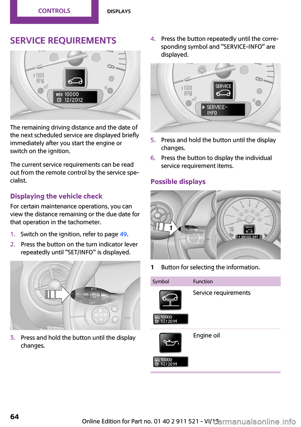
The remaining driving distance and the date of
the next scheduled service are displayed briefly
immediately after you start the engine or
switch on the ignition.
The current service requirements can be read
out from the remote control by the service spe‐
cialist.
Displaying the vehicle check
For certain maintenance operations, you can
view the distance remaining or the due date for
that operation in the tachometer.
1.Switch on the ignition, refer to page 49.2.Press the button on the turn indicator lever
repeatedly until "SET/INFO" is displayed.3.Press and hold the button until the display
changes.4.Press the button repeatedly until the corre‐
sponding symbol and "SERVICE-INFO" are
displayed.5.Press and hold the button until the display
changes.6.Press the button to display the individual
service requirement items.
Possible displays
1Button for selecting the information.SymbolFunctionService requirementsEngine oilSeite 64ControlsDisplays64
Online Edition for Part no. 01 40 2 911 521 - VI/13
Page 73 of 218
Protective action
Airbags are not triggered in every impact situa‐
tion, e.g., in less severe accidents or rear-end
collisions.
Information on how to ensure the opti‐
mal protective effect of the airbags▷Keep at a distance from the airbags.▷Always grasp the steering wheel on the
steering wheel rim, holding your hands at
the 3 o'clock and 9 o'clock positions, to
keep the danger of injury to your hands or
arms as low as possible if the airbag is trig‐
gered.▷There should be no people, animals, or ob‐
jects between an airbag and a person.▷Do not use the cover of the front airbag on
the front passenger side as a storage area.▷Keep the dashboard and window on the
front passenger side clear, i.e., do not cover
with adhesive labels or coverings, and do
not attach holders such as for navigation in‐
struments and mobile phones.▷Make sure that the front passenger is sitting
correctly, i.e., keeps his or her feet and legs
in the footwell; otherwise, leg injuries can
occur if the front airbag is triggered.▷Do not place slip covers, seat cushions or
other objects on the front passenger seat
that are not approved specifically for seats
with integrated side airbags.▷Do not hang pieces of clothing, such as
jackets, over the backrests.▷Make sure that occupants keep their heads
away from the side airbag and do not rest
against the head airbag; otherwise, injuries
can occur if the airbags are triggered.▷Do not remove the airbag restraint system.▷Do not remove the steering wheel.▷Do not apply adhesive materials to the air‐
bag cover panels, cover them or modify
them in any way.▷Never modify either the individual compo‐
nents or the wiring in the airbag system.
This also applies to steering wheel covers,
the dashboard, the seats, the roof pillars
and the sides of the headliner. ◀
Even when all instructions are followed closely,
injury from contact with the airbags cannot be
ruled out in certain situations.
The ignition and inflation noise may lead to
short-term and, in most cases, temporary hear‐
ing impairment in sensitive individuals.
In the case of a malfunction, deactivation
and after triggering of the airbags
Do not touch the individual components imme‐
diately after the system has been triggered;
otherwise, there is the danger of burns.
Only have the airbags checked, repaired or dis‐
mantled and the airbag generator scrapped by
your service center or a workshop that has the
necessary authorization for handling explo‐
sives.
Non-professional attempts to service the sys‐
tem could lead to failure in an emergency or
undesired triggering of the airbag, either of
which could result in injury. ◀
Warning notices and information about the air‐
bags can also be found on the sun visors.
Automatic deactivation of the front
passenger airbags
The system determines whether the front pas‐
senger seat is occupied by measuring the elec‐
trical resistance of the human body.
The front, side, and knee airbags on the front
passenger side are activated or deactivated ac‐
cordingly by the system.
The indicator lamp above the interior rearview
mirror, refer to page 74, shows the current
status of the front passenger airbags, deacti‐
vated or activated.
Seite 73SafetyControls73
Online Edition for Part no. 01 40 2 911 521 - VI/13
Page 76 of 218
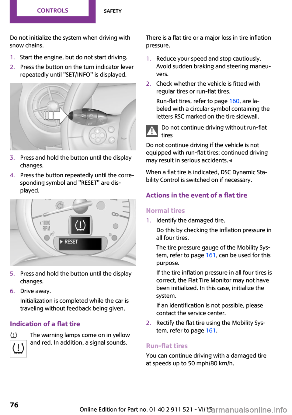
Do not initialize the system when driving with
snow chains.1.Start the engine, but do not start driving.2.Press the button on the turn indicator lever
repeatedly until "SET/INFO" is displayed.3.Press and hold the button until the display
changes.4.Press the button repeatedly until the corre‐
sponding symbol and "RESET" are dis‐
played.5.Press and hold the button until the display
changes.6.Drive away.
Initialization is completed while the car is
traveling without feedback being given.
Indication of a flat tire
The warning lamps come on in yellow
and red. In addition, a signal sounds.
There is a flat tire or a major loss in tire inflation
pressure.1.Reduce your speed and stop cautiously.
Avoid sudden braking and steering maneu‐
vers.2.Check whether the vehicle is fitted with
regular tires or run-flat tires.
Run-flat tires, refer to page 160, are la‐
beled with a circular symbol containing the
letters RSC marked on the tire sidewall.
Do not continue driving without run-flat
tires
Do not continue driving if the vehicle is not
equipped with run-flat tires; continued driving
may result in serious accidents. ◀
When a flat tire is indicated, DSC Dynamic Sta‐
bility Control is switched on if necessary.
Actions in the event of a flat tire
Normal tires
1.Identify the damaged tire.
Do this by checking the inflation pressure in
all four tires.
The tire pressure gauge of the Mobility Sys‐
tem, refer to page 161, can be used for this
purpose.
If the tire inflation pressure in all four tires is
correct, the Flat Tire Monitor may not have
been initialized. In this case, initialize the
system.
If an identification is not possible, please
contact the service center.2.Rectify the flat tire using the Mobility Sys‐
tem, refer to page 161.
Run-flat tires
You can continue driving with a damaged tire
at speeds up to 50 mph/80 km/h.
Seite 76ControlsSafety76
Online Edition for Part no. 01 40 2 911 521 - VI/13
Page 80 of 218

Final tire failure
Vibrations or loud noises while driving
can indicate the final failure of the tire. Reduce
speed and stop; otherwise, pieces of the tire
could come loose and cause an accident. Do
not continue driving, and contact your service
center. ◀
Malfunction The small warning lamp flashes in yel‐
low and then lights up continuously; the larger warning lamp comes on in yel‐
low.
No flat tire can be detected.
Display in the following situations:▷A wheel without TPM electronics is
mounted:
Have the system checked by the service
center if necessary.▷Malfunction:
Have the system checked.▷TPM could not be fully reset; reset the sys‐
tem again.
The small warning lamp flashes in yel‐
low and then lights up continuously; the
larger warning lamp comes on in yel‐
low.
No flat tire can be detected.
Display in the following situation:
▷Disturbance by other systems or devices
with the same radio frequency
After leaving the area of the disturbance,
the system automatically becomes active
again.
Declaration according to NHTSA/FMVSS
138 Tire Pressure Monitoring Systems
Each tire, including the spare (if provided)
should be checked monthly when cold and in‐
flated to the inflation pressure recommended
by the vehicle manufacturer on the vehicle
placard or tire inflation pressure label (If your
vehicle has tires of a different size than the size
indicated on the vehicle placard or tire inflation
pressure label, you should determine the
proper tire inflation pressure for those tires.).
As an added safety feature, your vehicle has
been equipped with a tire pressure monitoring
system (TPMS) that illuminates a low tire pres‐
sure telltale when one or more of your tires is
significantly under-inflated. Accordingly, when
the low tire pressure telltale illuminates, you
should stop and check your tires as soon as
possible, and inflate them to the proper pres‐
sure. Driving on a significantly under-inflated
tire causes the tire to overheat and can lead to
tire failure. Under-inflation also reduces fuel ef‐
ficiency and tire tread life, and may affect the
vehicle's handling and stopping ability.
Please note that the TPMS is not a substitute for
proper tire maintenance, and it is the driver's
responsibility to maintain correct tire pressure,
even if under-inflation has not reached the
level to trigger illumination of the TPMS low tire
pressure telltale.
Your vehicle has also been equipped with a
TPMS malfunction indicator to indicate when
the system is not operating properly. The TPMS
malfunction indicator is combined with the low
tire pressure telltale. When the system detects
a malfunction, the telltale will flash for approxi‐
mately one minute and then remain continu‐
ously illuminated. This sequence will continue
upon subsequent vehicle startups as long as
the malfunction exists. When the malfunction
indicator is illuminated, the system may not be
able to detect or signal low tire pressure as in‐
tended. TPMS malfunctions may occur for a va‐
riety of reasons, including the installation of re‐
placement or alternate tires or wheels on the
vehicle that prevent the TPMS from functioning
properly. Always check the TPMS malfunction
telltale after replacing one or more tires or
wheels on your vehicle to ensure that the re‐
placement or alternate tires and wheels allow
the TPMS to continue to function properly.Seite 80ControlsSafety80
Online Edition for Part no. 01 40 2 911 521 - VI/13
Page 158 of 218

Minimum tread depth
Wear indicators in the tread base are distrib‐
uted around the circumference of the tire and
are marked on the tire sidewall with TWI, Tread
Wear Indicator. When the tire tread has been
worn down to the wear indicators, a tread has
reached a depth of 0.063 in/1.6 mm.
Tire damage
General information Inspect your tires often for damage, foreign ob‐
jects lodged in the tread, and tread wear.
Notes
Driving over rough or damaged road surfaces,
as well as debris, curbs and other obstacles can
cause serious damage to wheels, tires and sus‐
pension parts. This is more likely to occur with
low-profile tires, which provide less cushioning
between the wheel and the road. Be careful to
avoid road hazards and reduce your speed, es‐
pecially if your vehicle is equipped with low-
profile tires.
Indications of tire damage or other vehicle de‐
fects:
▷Unusual vibrations during driving.▷Unusual handling such as a strong ten‐
dency to pull to the left or right.
Damage can be caused by driving over curbs,
road damage and similar situations.
In case of tire damage
If there are indications of tire damage, re‐
duce your speed immediately and have the
wheels and tires checked right away; other‐
wise, there is the increased risk of an accident.
Drive carefully to the next service center or tire
shop.
If necessary, have the vehicle towed.
Otherwise, tire damage can present a life-
threatening hazard to vehicle occupants and
other road users. ◀
Repair of tire damage
For safety reasons, the manufacturer of
your vehicle recommends that you do not have
damaged tires repaired; they should be re‐
placed. Otherwise, damage can occur as a re‐
sult. ◀
Tire age RecommendationFor several reasons, among other things be‐
cause of beginning brittleness, the manufac‐
turer of your MINI recommends mounting new
tires at the latest after six years, regardless of
the actual wear.
Manufacture date The date of manufacture of the tires is specified
in the tire label:
DOT … 2313: the tire was manufactured in
week 23 of 2013.Seite 158MobilityWheels and tires158
Online Edition for Part no. 01 40 2 911 521 - VI/13
Page 191 of 218
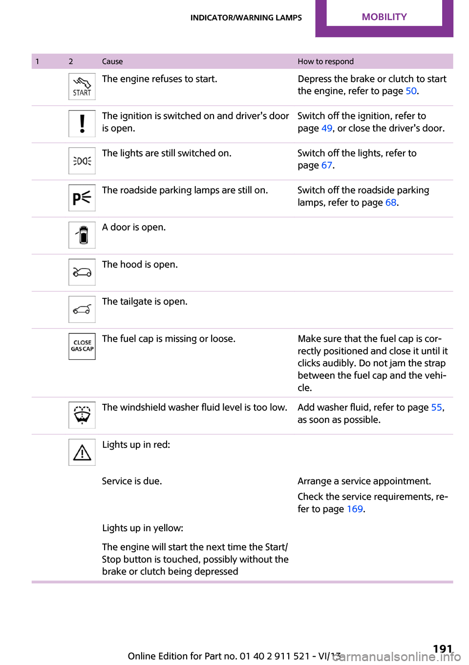
12CauseHow to respondThe engine refuses to start.Depress the brake or clutch to start
the engine, refer to page 50.The ignition is switched on and driver's door
is open.Switch off the ignition, refer to
page 49, or close the driver's door.The lights are still switched on.Switch off the lights, refer to
page 67.The roadside parking lamps are still on.Switch off the roadside parking
lamps, refer to page 68.A door is open.The hood is open.The tailgate is open.The fuel cap is missing or loose.Make sure that the fuel cap is cor‐
rectly positioned and close it until it
clicks audibly. Do not jam the strap
between the fuel cap and the vehi‐
cle.The windshield washer fluid level is too low.Add washer fluid, refer to page 55,
as soon as possible.Lights up in red:Service is due.Arrange a service appointment.
Check the service requirements, re‐
fer to page 169.Lights up in yellow:The engine will start the next time the Start/
Stop button is touched, possibly without the
brake or clutch being depressedSeite 191Indicator/warning lampsMobility191
Online Edition for Part no. 01 40 2 911 521 - VI/13
Page 192 of 218
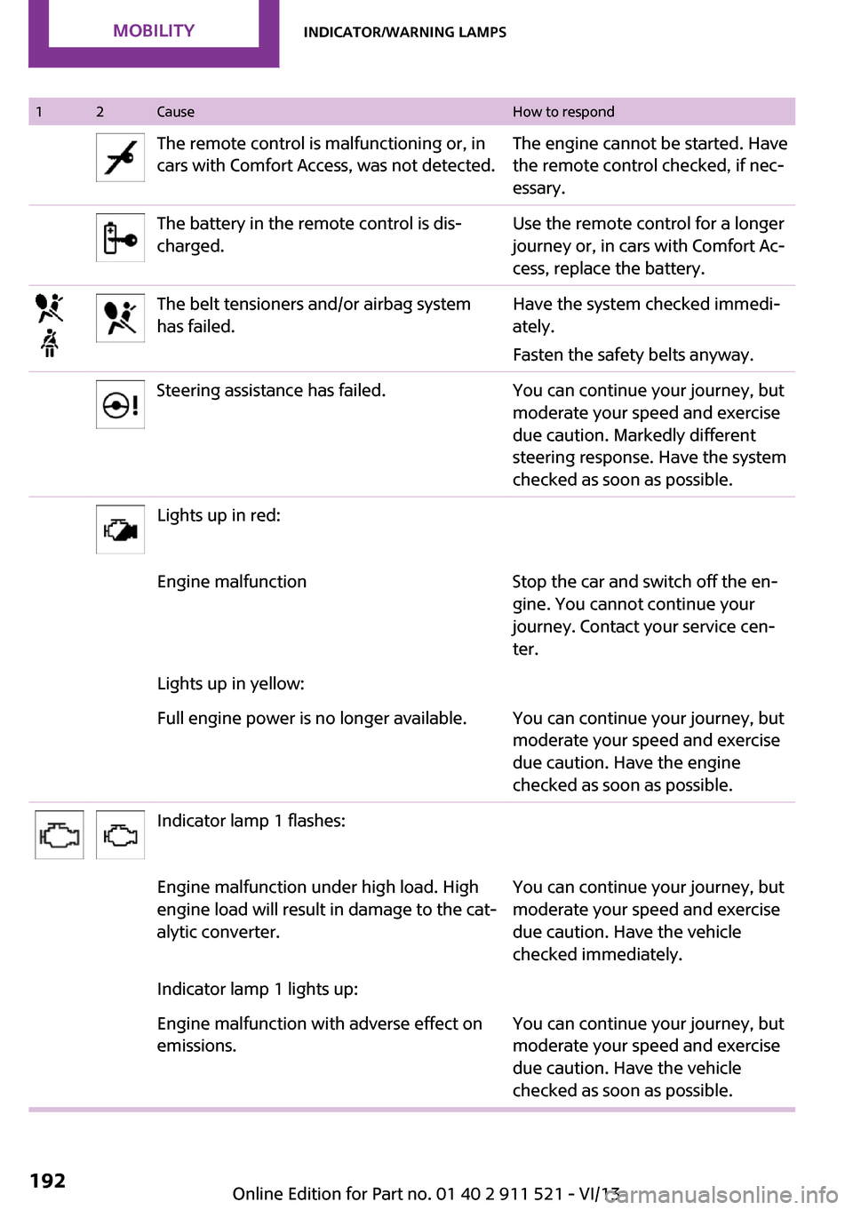
12CauseHow to respondThe remote control is malfunctioning or, in
cars with Comfort Access, was not detected.The engine cannot be started. Have
the remote control checked, if nec‐
essary.The battery in the remote control is dis‐
charged.Use the remote control for a longer
journey or, in cars with Comfort Ac‐
cess, replace the battery.The belt tensioners and/or airbag system
has failed.Have the system checked immedi‐
ately.
Fasten the safety belts anyway.Steering assistance has failed.You can continue your journey, but
moderate your speed and exercise
due caution. Markedly different
steering response. Have the system
checked as soon as possible.Lights up in red:Engine malfunctionStop the car and switch off the en‐
gine. You cannot continue your
journey. Contact your service cen‐
ter.Lights up in yellow:Full engine power is no longer available.You can continue your journey, but
moderate your speed and exercise
due caution. Have the engine
checked as soon as possible.Indicator lamp 1 flashes:Engine malfunction under high load. High
engine load will result in damage to the cat‐
alytic converter.You can continue your journey, but
moderate your speed and exercise
due caution. Have the vehicle
checked immediately.Indicator lamp 1 lights up:Engine malfunction with adverse effect on
emissions.You can continue your journey, but
moderate your speed and exercise
due caution. Have the vehicle
checked as soon as possible.Seite 192MobilityIndicator/warning lamps192
Online Edition for Part no. 01 40 2 911 521 - VI/13