warning MINI Paceman 2014 Owner's Manual
[x] Cancel search | Manufacturer: MINI, Model Year: 2014, Model line: Paceman, Model: MINI Paceman 2014Pages: 218, PDF Size: 5.5 MB
Page 5 of 218
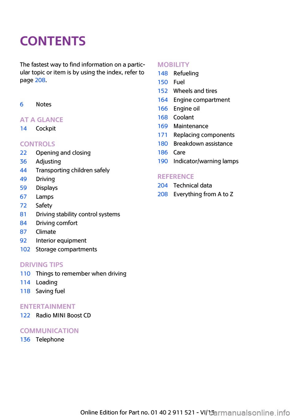
ContentsThe fastest way to find information on a partic‐
ular topic or item is by using the index, refer to
page 208.6Notes
At a glance
14Cockpit
Controls
22Opening and closing36Adjusting44Transporting children safely49Driving59Displays67Lamps72Safety81Driving stability control systems84Driving comfort87Climate92Interior equipment102Storage compartments
Driving tips
110Things to remember when driving114Loading118Saving fuel
Entertainment
122Radio MINI Boost CD
Communication
136TelephoneMobility148Refueling150Fuel152Wheels and tires164Engine compartment166Engine oil168Coolant169Maintenance171Replacing components180Breakdown assistance186Care190Indicator/warning lamps
Reference
204Technical data208Everything from A to Z
Online Edition for Part no. 01 40 2 911 521 - VI/13
Page 7 of 218
For your own safety
Warranty Your vehicle is technically configured for the
operating conditions and registration require‐
ments applying in the country of first delivery
— homologation. If your vehicle is to be oper‐
ated in a different country it might be neces‐
sary to adapt your vehicle to potentially differ‐
ing operating conditions and permit
requirements. If your vehicle does not comply
with the homologation requirements in a cer‐
tain country you cannot lodge warranty claims
for your vehicle there. Further information can
be obtained from your Service Centre.
Maintenance and repairs Advanced technology, e.g., the use of modern
materials and high-performance electronics,
requires suitable maintenance and repair
methods.
Therefore, have this work performed only by a
MINI service center or a workshop that works
according to MINI repair procedures with ap‐
propriately trained personnel.
If this work is not carried out properly, there is
the danger of subsequent damage and related
safety hazards.
Parts and accessories
For your own safety, use genuine parts and ac‐
cessories approved by the manufacturer of the
MINI. When you purchase accessories tested
and approved by the manufacturer of the MINI
and Original MINI Parts, you simultaneously ac‐
quire the assurance that they have been thor‐
oughly tested by the manufacturer of the MINI
to ensure optimum performance when instal‐
led on your vehicle. The manufacturer of the
MINI warrants these parts to be free from de‐
fects in material and workmanship. The manu‐
facturer of the MINI will not accept any liability
for damage resulting from installation of parts
and accessories not approved by the manufac‐turer of the MINI. The manufacturer of the MINI
cannot test every product made by other man‐
ufacturers to verify if it can be used on a MINI
safely and without risk to either the vehicle, its
operation, or its occupants. Original MINI Parts,
MINI Accessories and other products approved
by the manufacturer of the MINI, together with
professional advice on using these items, are
available from all MINI Dealers. Installation and
operation of non-MINI approved accessories
such as alarms, radios, amplifiers, radar detec‐
tors, wheels, suspension components, brake
dust shields, telephones, including operation of
any mobile phone from within the vehicle with‐
out using an externally mounted antenna, or
transceiver equipment, for instance, CBs,
walkie-talkies, ham radios or similar accesso‐
ries, may cause extensive damage to the vehi‐
cle, compromise its safety, interfere with the
vehicle's electrical system or affect the validity
of the MINI Limited Warranty. See your MINI
Dealer for additional information. Maintenance,
replacement, or repair of the emission control
devices and systems may be performed by any
automotive repair establishment or individual
using any certified automotive part.
California Proposition 65 Warning
California laws require us to state the following
warning:
Engine exhaust and a wide variety of automo‐
bile components and parts, including compo‐
nents found in the interior furnishings in a vehi‐
cle, contain or emit chemicals known to the
State of California to cause cancer and birth de‐
fects and reproductive harm. In addition, cer‐
tain fluids contained in vehicles and certain
products of component wear contain or emit
chemicals known to the State of California to
cause cancer and birth defects or other repro‐
ductive harm. Battery posts, terminals and re‐
lated accessories contain lead and lead com‐
pounds. Wash your hands after handling. Used
engine oil contains chemicals that have caused
cancer in laboratory animals. Always protectSeite 7Notes7
Online Edition for Part no. 01 40 2 911 521 - VI/13
Page 16 of 218
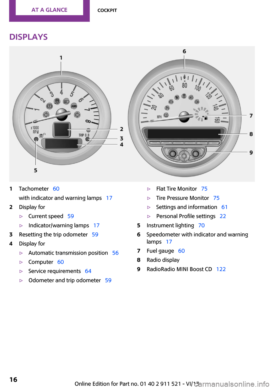
Displays1Tachometer 60
with indicator and warning lamps 172Display for▷Current speed 59▷Indicator/warning lamps 173Resetting the trip odometer 594Display for▷Automatic transmission position 56▷Computer 60▷Service requirements 64▷Odometer and trip odometer 59▷Flat Tire Monitor 75▷Tire Pressure Monitor 75▷Settings and information 61▷Personal Profile settings 225Instrument lighting 706Speedometer with indicator and warning
lamps 177Fuel gauge 608Radio display9RadioRadio MINI Boost CD 122Seite 16At a glanceCockpit16
Online Edition for Part no. 01 40 2 911 521 - VI/13
Page 17 of 218
Indicator/warning lamps
The concept
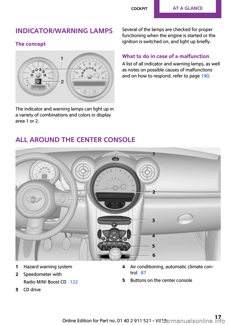
The indicator and warning lamps can light up in
a variety of combinations and colors in display
area 1 or 2.
Several of the lamps are checked for proper
functioning when the engine is started or the
ignition is switched on, and light up briefly.
What to do in case of a malfunction
A list of all indicator and warning lamps, as well
as notes on possible causes of malfunctions
and on how to respond, refer to page 190.
All around the center console
1Hazard warning system2Speedometer with
Radio MINI Boost CD 1223CD drive4Air conditioning, automatic climate con‐
trol 875Buttons on the center consoleSeite 17CockpitAt a glance17
Online Edition for Part no. 01 40 2 911 521 - VI/13
Page 18 of 218
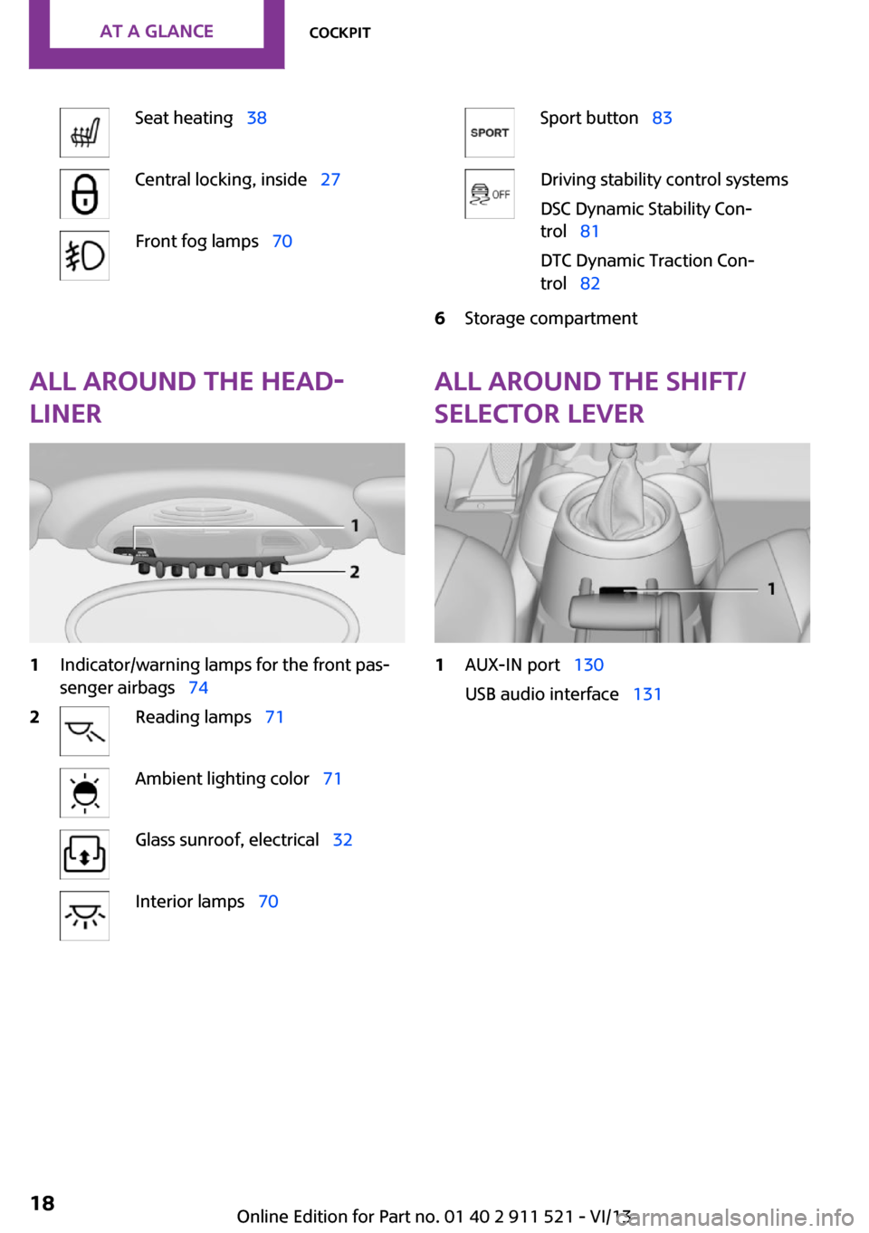
Seat heating 38Central locking, inside 27Front fog lamps 70Sport button 83Driving stability control systems
DSC Dynamic Stability Con‐
trol 81
DTC Dynamic Traction Con‐
trol 826Storage compartmentAll around the head‐
liner1Indicator/warning lamps for the front pas‐
senger airbags 742Reading lamps 71Ambient lighting color 71Glass sunroof, electrical 32Interior lamps 70All around the shift/
selector lever1AUX-IN port 130
USB audio interface 131Seite 18At a glanceCockpit18
Online Edition for Part no. 01 40 2 911 521 - VI/13
Page 24 of 218
The hazard warning system and interior lamps
come on.
Opening and closing:
from the outside
Using the remote control
General information Take the remote control with you
People or animals left unattended in a
parked vehicle can lock the doors from the in‐
side. Always take the remote control with you
when leaving the vehicle so that the vehicle
can then be opened from the outside. ◀
Unlocking
Press the button. The vehicle is un‐
locked.
The welcome lamps and interior lamps are
switched on.
You can set how the vehicle is to be unlocked.
The setting is stored for the remote control cur‐
rently in use.
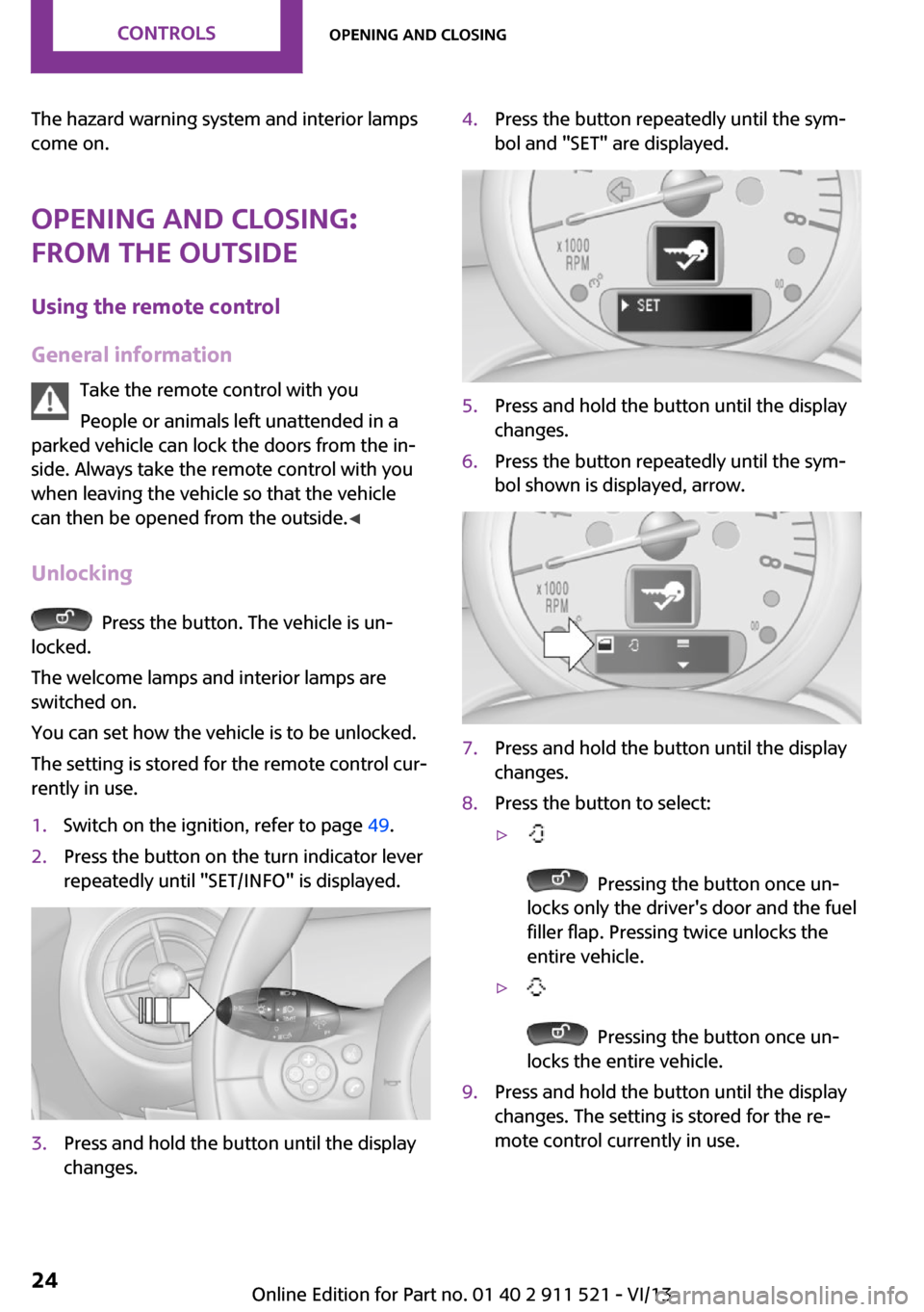
1.Switch on the ignition, refer to page 49.2.Press the button on the turn indicator lever
repeatedly until "SET/INFO" is displayed.3.Press and hold the button until the display
changes.4.Press the button repeatedly until the sym‐
bol and "SET" are displayed.5.Press and hold the button until the display
changes.6.Press the button repeatedly until the sym‐
bol shown is displayed, arrow.7.Press and hold the button until the display
changes.8.Press the button to select:▷
Pressing the button once un‐
locks only the driver's door and the fuel
filler flap. Pressing twice unlocks the
entire vehicle.
▷
Pressing the button once un‐
locks the entire vehicle.
9.Press and hold the button until the display
changes. The setting is stored for the re‐
mote control currently in use.Seite 24ControlsOpening and closing24
Online Edition for Part no. 01 40 2 911 521 - VI/13
Page 25 of 218
Convenient opening
Press and hold the button on the re‐
mote control.
The power windows are opened and the glass
sunroof is raised.
Convenient closing with the remote control is
not possible.
Locking
Press the button.
Locking from the outside
Do not lock the vehicle from the outside if
there are people in it, as the vehicle cannot be
unlocked from inside without special knowl‐
edge. ◀
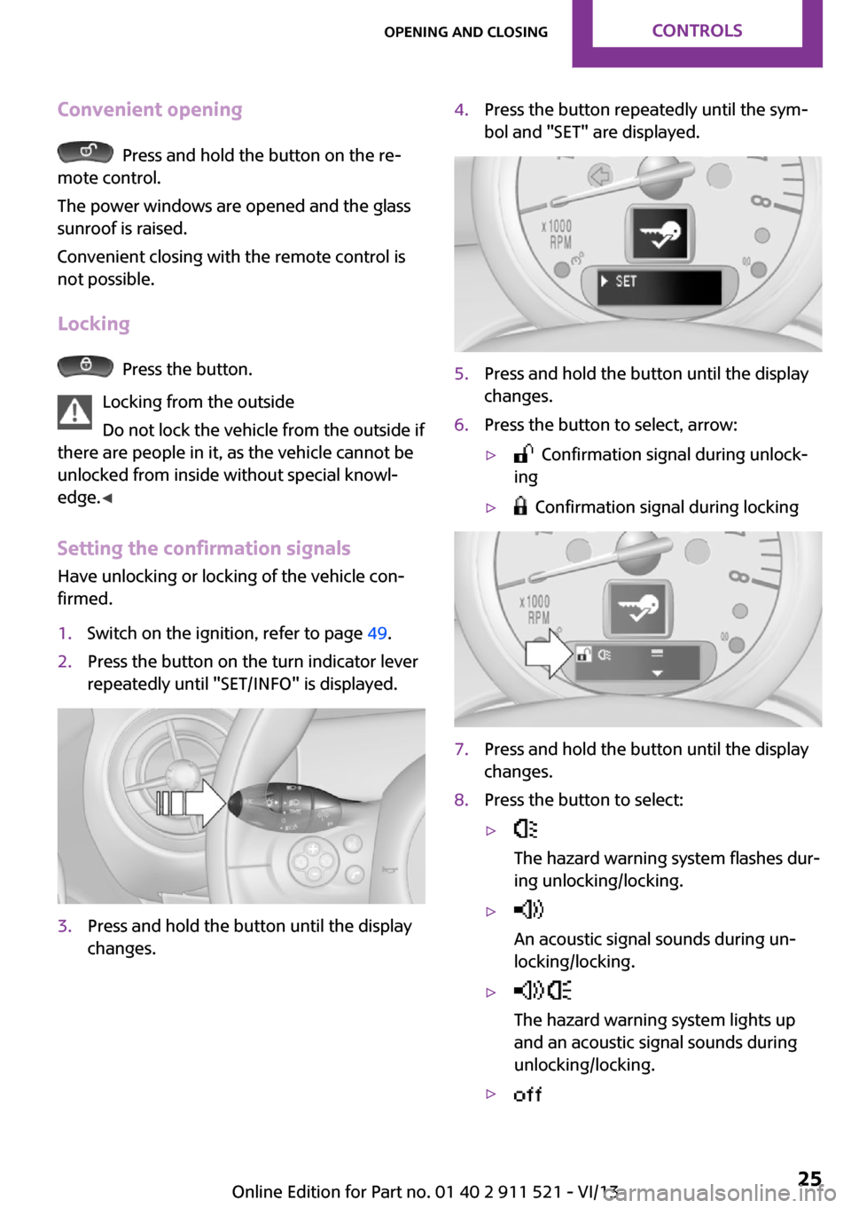
Setting the confirmation signals
Have unlocking or locking of the vehicle con‐
firmed.
1.Switch on the ignition, refer to page 49.2.Press the button on the turn indicator lever
repeatedly until "SET/INFO" is displayed.3.Press and hold the button until the display
changes.4.Press the button repeatedly until the sym‐
bol and "SET" are displayed.5.Press and hold the button until the display
changes.6.Press the button to select, arrow:▷ Confirmation signal during unlock‐
ing▷ Confirmation signal during locking7.Press and hold the button until the display
changes.8.Press the button to select:▷
The hazard warning system flashes dur‐
ing unlocking/locking.▷
An acoustic signal sounds during un‐
locking/locking.▷
The hazard warning system lights up
and an acoustic signal sounds during
unlocking/locking.▷ Seite 25Opening and closingControls25
Online Edition for Part no. 01 40 2 911 521 - VI/13
Page 31 of 218
If a remote control accidentally left in the cargo
area is detected in the locked vehicle after the
tailgate is closed, the tailgate opens again
slightly. The hazard warning system flashes and
an acoustic signal sounds.
Power windows and electrical glass
sunroof
When the engine is switched off, the windows
and the sunroof can be operated as long as
neither the doors nor the tailgate are opened.
When the door and tailgate are closed again
and the remote control is detected inside the
vehicle, the windows and the sunroof can be
operated again.
Insert the remote control into the ignition lock
to be able to operate the windows and the sun‐
roof while the engine is switched off and the
doors are open.
Switching on the radio ready state Press the Start/Stop button to switch on the
radio ready state, refer to page 49.
Do not depress the brake or the clutch; other‐
wise, the engine will start.
Starting the engine The engine can be started or the ignition can
be switched on, refer to page 49, when a re‐
mote control is inside the vehicle. It is not nec‐
essary to insert a remote control into the igni‐
tion lock.
Switching off the engine in cars with
automatic transmission
The engine can only be switched off with the
selector lever in position P, refer to page 56.
To switch off the engine with the selector lever
in position N, the remote control must be in‐
serted in the ignition lock.Before driving a vehicle with automatic
transmission into a car wash1.Insert the remote control into the ignition
switch.2.Depress the brake pedal.3.Move the selector lever to position N.4.Switch the engine off.
The vehicle can roll.
Malfunction The Comfort Access functions can be disturbed
by local radio waves, such as by a mobile
phone in the immediate vicinity of the remote
control or when a mobile phone is being
charged in the vehicle.
If this occurs, open or close the vehicle using
the buttons on the remote control or use the
integrated key in the door lock.
To start the engine afterward, insert the remote
control into the ignition switch.
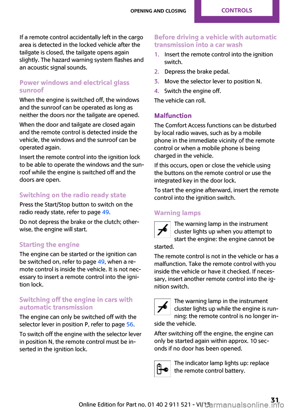
Warning lamps The warning lamp in the instrument
cluster lights up when you attempt to
start the engine: the engine cannot be
started.
The remote control is not in the vehicle or has a
malfunction. Take the remote control with you
inside the vehicle or have it checked. If neces‐
sary, insert another remote control into the ig‐
nition switch.
The warning lamp in the instrument
cluster lights up while the engine is run‐
ning: the remote control is no longer in‐
side the vehicle.
After switching off the engine, the engine can
only be started again within approx. 10 sec‐
onds if no door has been opened.
The indicator lamp lights up: replace
the remote control battery.
Seite 31Opening and closingControls31
Online Edition for Part no. 01 40 2 911 521 - VI/13
Page 32 of 218
Replacing the battery
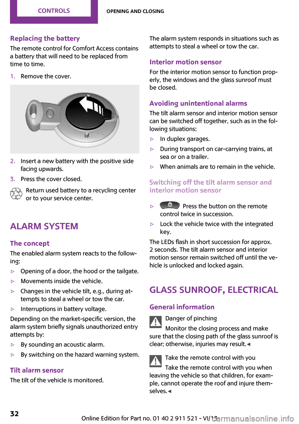
The remote control for Comfort Access contains
a battery that will need to be replaced from
time to time.1.Remove the cover.2.Insert a new battery with the positive side
facing upwards.3.Press the cover closed.
Return used battery to a recycling center
or to your service center.
Alarm system
The concept
The enabled alarm system reacts to the follow‐
ing:
▷Opening of a door, the hood or the tailgate.▷Movements inside the vehicle.▷Changes in the vehicle tilt, e.g., during at‐
tempts to steal a wheel or tow the car.▷Interruptions in battery voltage.
Depending on the market-specific version, the
alarm system briefly signals unauthorized entry
attempts by:
▷By sounding an acoustic alarm.▷By switching on the hazard warning system.
Tilt alarm sensor
The tilt of the vehicle is monitored.
The alarm system responds in situations such as
attempts to steal a wheel or tow the car.
Interior motion sensor For the interior motion sensor to function prop‐
erly, the windows and the glass sunroof must
be closed.
Avoiding unintentional alarms
The tilt alarm sensor and interior motion sensor
can be switched off together, such as in the fol‐
lowing situations:▷In duplex garages.▷During transport on car-carrying trains, at
sea or on a trailer.▷When animals are to remain in the vehicle.
Switching off the tilt alarm sensor and
interior motion sensor
▷ Press the button on the remote
control twice in succession.▷Lock the vehicle twice with the integrated
key.
The LEDs flash in short succession for approx.
2 seconds. The tilt alarm sensor and interior
motion sensor remain switched off until the ve‐
hicle is unlocked and locked again.
Glass sunroof, electrical
General information Danger of pinching
Monitor the closing process and make
sure that the closing path of the glass sunroof is
clear; otherwise, injuries may result. ◀
Take the remote control with you
Take the remote control with you when
leaving the vehicle so that children, for exam‐
ple, cannot operate the roof and injure them‐
selves. ◀
Seite 32ControlsOpening and closing32
Online Edition for Part no. 01 40 2 911 521 - VI/13
Page 49 of 218
DrivingVehicle equipmentThis chapter describes all series equipment as
well as country-specific and special equipment
offered for this model series.Therefore, it also
describes equipment that may not be found in
your vehicle, for instance due to the selected
special equipment or the country version. This
also applies to safety-related functions and sys‐
tems.
Ignition lock Insert the remote control into the
ignition lock
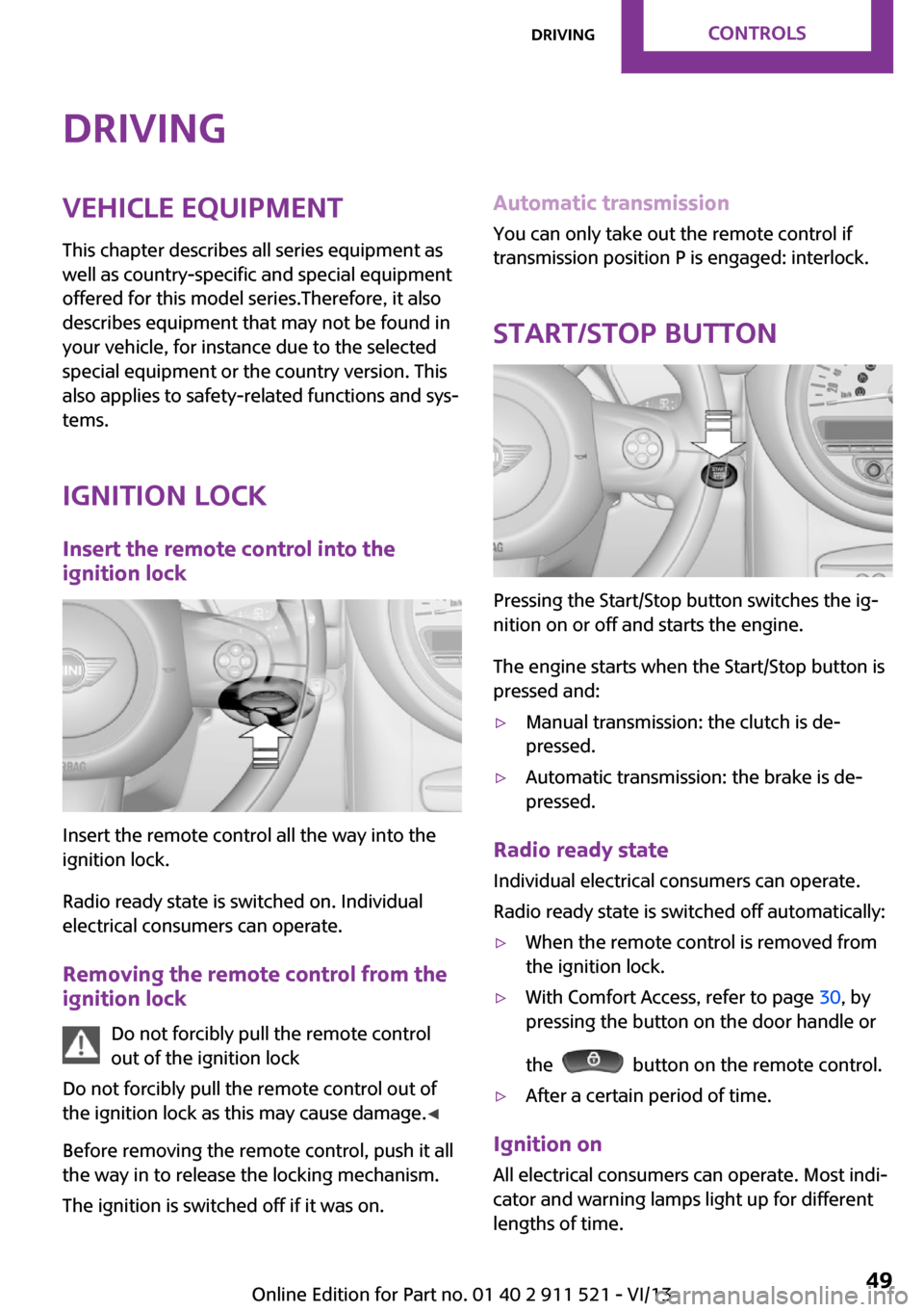
Insert the remote control all the way into the
ignition lock.
Radio ready state is switched on. Individual
electrical consumers can operate.
Removing the remote control from the
ignition lock
Do not forcibly pull the remote control
out of the ignition lock
Do not forcibly pull the remote control out of
the ignition lock as this may cause damage. ◀
Before removing the remote control, push it all
the way in to release the locking mechanism.
The ignition is switched off if it was on.
Automatic transmission
You can only take out the remote control if
transmission position P is engaged: interlock.
Start/Stop button
Pressing the Start/Stop button switches the ig‐
nition on or off and starts the engine.
The engine starts when the Start/Stop button is
pressed and:
▷Manual transmission: the clutch is de‐
pressed.▷Automatic transmission: the brake is de‐
pressed.
Radio ready state
Individual electrical consumers can operate.
Radio ready state is switched off automatically:
▷When the remote control is removed from
the ignition lock.▷With Comfort Access, refer to page 30, by
pressing the button on the door handle or
the
button on the remote control.
▷After a certain period of time.
Ignition on All electrical consumers can operate. Most indi‐
cator and warning lamps light up for different
lengths of time.
Seite 49DrivingControls49
Online Edition for Part no. 01 40 2 911 521 - VI/13