wheel size MINI Paceman 2014 Owner's Manual
[x] Cancel search | Manufacturer: MINI, Model Year: 2014, Model line: Paceman, Model: MINI Paceman 2014Pages: 218, PDF Size: 5.5 MB
Page 80 of 218

Final tire failure
Vibrations or loud noises while driving
can indicate the final failure of the tire. Reduce
speed and stop; otherwise, pieces of the tire
could come loose and cause an accident. Do
not continue driving, and contact your service
center. ◀
Malfunction The small warning lamp flashes in yel‐
low and then lights up continuously; the larger warning lamp comes on in yel‐
low.
No flat tire can be detected.
Display in the following situations:▷A wheel without TPM electronics is
mounted:
Have the system checked by the service
center if necessary.▷Malfunction:
Have the system checked.▷TPM could not be fully reset; reset the sys‐
tem again.
The small warning lamp flashes in yel‐
low and then lights up continuously; the
larger warning lamp comes on in yel‐
low.
No flat tire can be detected.
Display in the following situation:
▷Disturbance by other systems or devices
with the same radio frequency
After leaving the area of the disturbance,
the system automatically becomes active
again.
Declaration according to NHTSA/FMVSS
138 Tire Pressure Monitoring Systems
Each tire, including the spare (if provided)
should be checked monthly when cold and in‐
flated to the inflation pressure recommended
by the vehicle manufacturer on the vehicle
placard or tire inflation pressure label (If your
vehicle has tires of a different size than the size
indicated on the vehicle placard or tire inflation
pressure label, you should determine the
proper tire inflation pressure for those tires.).
As an added safety feature, your vehicle has
been equipped with a tire pressure monitoring
system (TPMS) that illuminates a low tire pres‐
sure telltale when one or more of your tires is
significantly under-inflated. Accordingly, when
the low tire pressure telltale illuminates, you
should stop and check your tires as soon as
possible, and inflate them to the proper pres‐
sure. Driving on a significantly under-inflated
tire causes the tire to overheat and can lead to
tire failure. Under-inflation also reduces fuel ef‐
ficiency and tire tread life, and may affect the
vehicle's handling and stopping ability.
Please note that the TPMS is not a substitute for
proper tire maintenance, and it is the driver's
responsibility to maintain correct tire pressure,
even if under-inflation has not reached the
level to trigger illumination of the TPMS low tire
pressure telltale.
Your vehicle has also been equipped with a
TPMS malfunction indicator to indicate when
the system is not operating properly. The TPMS
malfunction indicator is combined with the low
tire pressure telltale. When the system detects
a malfunction, the telltale will flash for approxi‐
mately one minute and then remain continu‐
ously illuminated. This sequence will continue
upon subsequent vehicle startups as long as
the malfunction exists. When the malfunction
indicator is illuminated, the system may not be
able to detect or signal low tire pressure as in‐
tended. TPMS malfunctions may occur for a va‐
riety of reasons, including the installation of re‐
placement or alternate tires or wheels on the
vehicle that prevent the TPMS from functioning
properly. Always check the TPMS malfunction
telltale after replacing one or more tires or
wheels on your vehicle to ensure that the re‐
placement or alternate tires and wheels allow
the TPMS to continue to function properly.Seite 80ControlsSafety80
Online Edition for Part no. 01 40 2 911 521 - VI/13
Page 152 of 218
Wheels and tiresVehicle equipment
This chapter describes all series equipment as
well as country-specific and special equipment
offered for this model series.Therefore, it also
describes equipment that may not be found in
your vehicle, for instance due to the selected
special equipment or the country version. This
also applies to safety-related functions and sys‐
tems.
Tire inflation pressure Safety information
It is not merely the tires' service life, but also
driving comfort and, to a great extent, driving
safety that depend on the condition of the tires
and the maintenance of the specified tire pres‐
sure.
Checking the pressure Check the tire inflation pressure regularly
Regularly check the tire inflation pressure
and correct it as needed: at least twice a month
and before a long trip. If you fail to observe this
precaution, you may be driving on tires with in‐
correct tire pressures, a condition that may not
only compromise your vehicle's driving stabil‐
ity, but also lead to tire damage and the risk of
an accident.
Do not drive with depressurized or flat tires, ex‐
cept for run-flat tires. A flat tire will seriously
impair your vehicle's handling and braking re‐
sponse. Attempts to drive on a flat tire can lead
to a loss of control over the vehicle. ◀
Only check the tire inflation pressure when the
tires are cold. This means after a maximum of
1.25 miles/2 km driving or when the vehicle
has been parked for at least 2 hours. When thetires are warm, the tire inflation pressure is
higher.
After correcting the tire inflation pressure, reset
the Tire Pressure Monitor, refer to page 78
or reinitialize the Flat Tire Monitor, refer to
page 75.
To check the inflation pressure, there is a valve
extension behind the bumper.
Pressure specifications
The tables below provide all the correct infla‐
tion pressures for the specified tire sizes at am‐
bient temperature.
The inflation pressures apply to the tire sizes
approved and tire brands recommended by the
manufacturer of the MINI; a list of these is
available from the service center.
For correct identification of the right tire infla‐
tion pressures, observe the following:▷Tire sizes of your vehicle▷Maximum allowable driving speed
Tire inflation pressures for driving up to
100 mph or 160 km/h
For normal driving up to 100 mph/160 km/h,
adjust pressures to the respective tire inflation
pressures listed on the following pages in the
column for traveling speeds up to 100 mph/
160 km/h to achieve optimum driving comfort.
These tire inflation pressures can also be found
on the driver's side door pillar when the driver's
door is open.
Seite 152MobilityWheels and tires152
Online Edition for Part no. 01 40 2 911 521 - VI/13
Page 153 of 218
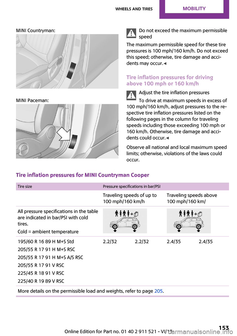
MINI Countryman:
MINI Paceman:
Do not exceed the maximum permissible
speed
The maximum permissible speed for these tire
pressures is 100 mph/160 km/h. Do not exceed
this speed; otherwise, tire damage and acci‐
dents may occur. ◀
Tire inflation pressures for driving
above 100 mph or 160 km/h
Adjust the tire inflation pressures
To drive at maximum speeds in excess of
100 mph/160 km/h, adjust pressures to the re‐
spective tire inflation pressures listed on the
following pages in the column for traveling
speeds including those exceeding 100 mph or
160 km/h. Otherwise, tire damage and acci‐
dents could occur. ◀
Observe all national and local maximum speed limits; otherwise, violations of the laws could
occur.
Tire inflation pressures for MINI Countryman Cooper
Tire sizePressure specifications in bar/PSITraveling speeds of up to
100 mph/160 km/hTraveling speeds above
100 mph/160 km/All pressure specifications in the table are indicated in bar/PSI with cold
tires.
Cold = ambient temperature195/60 R 16 89 H M+S Std
205/55 R 17 91 H M+S RSC
205/55 R 17 91 H M+S A/S RSC
205/55 R 17 91 V RSC
225/45 R 18 91 V RSC
225/40 R 19 89 V RSC2.2/322.2/322.4/352.4/35More details on the permissible load and weights, refer to page 205.Seite 153Wheels and tiresMobility153
Online Edition for Part no. 01 40 2 911 521 - VI/13
Page 154 of 218
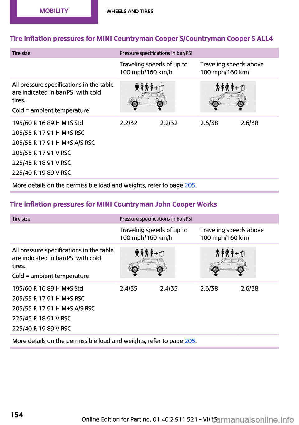
Tire inflation pressures for MINI Countryman Cooper S/Countryman Cooper S ALL4
Tire sizePressure specifications in bar/PSITraveling speeds of up to
100 mph/160 km/hTraveling speeds above
100 mph/160 km/All pressure specifications in the table are indicated in bar/PSI with cold
tires.
Cold = ambient temperature195/60 R 16 89 H M+S Std
205/55 R 17 91 H M+S RSC
205/55 R 17 91 H M+S A/S RSC
205/55 R 17 91 V RSC
225/45 R 18 91 V RSC
225/40 R 19 89 V RSC2.2/322.2/322.6/382.6/38More details on the permissible load and weights, refer to page 205.
Tire inflation pressures for MINI Countryman John Cooper Works
Tire sizePressure specifications in bar/PSITraveling speeds of up to
100 mph/160 km/hTraveling speeds above
100 mph/160 km/All pressure specifications in the table are indicated in bar/PSI with cold
tires.
Cold = ambient temperature195/60 R 16 89 H M+S Std
205/55 R 17 91 H M+S RSC
205/55 R 17 91 H M+S A/S RSC
225/45 R 18 91 V RSC
225/40 R 19 89 V RSC2.4/352.4/352.6/382.6/38More details on the permissible load and weights, refer to page 205.Seite 154MobilityWheels and tires154
Online Edition for Part no. 01 40 2 911 521 - VI/13
Page 155 of 218
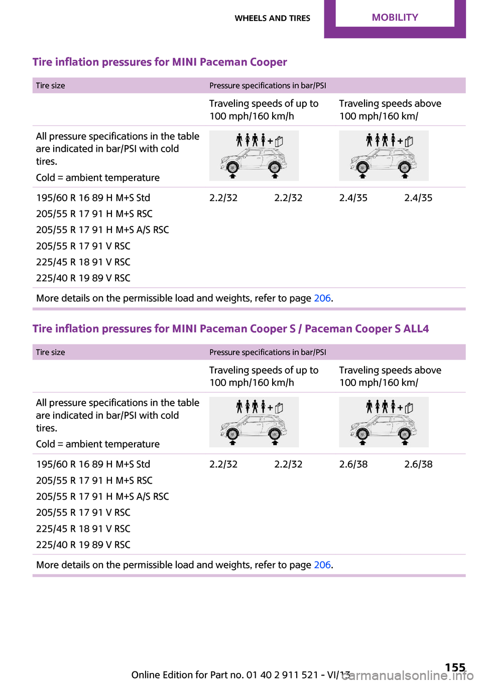
Tire inflation pressures for MINI Paceman Cooper
Tire sizePressure specifications in bar/PSITraveling speeds of up to
100 mph/160 km/hTraveling speeds above
100 mph/160 km/All pressure specifications in the table are indicated in bar/PSI with cold
tires.
Cold = ambient temperature195/60 R 16 89 H M+S Std
205/55 R 17 91 H M+S RSC
205/55 R 17 91 H M+S A/S RSC
205/55 R 17 91 V RSC
225/45 R 18 91 V RSC
225/40 R 19 89 V RSC2.2/322.2/322.4/352.4/35More details on the permissible load and weights, refer to page 206.
Tire inflation pressures for MINI Paceman Cooper S / Paceman Cooper S ALL4
Tire sizePressure specifications in bar/PSITraveling speeds of up to
100 mph/160 km/hTraveling speeds above
100 mph/160 km/All pressure specifications in the table are indicated in bar/PSI with cold
tires.
Cold = ambient temperature195/60 R 16 89 H M+S Std
205/55 R 17 91 H M+S RSC
205/55 R 17 91 H M+S A/S RSC
205/55 R 17 91 V RSC
225/45 R 18 91 V RSC
225/40 R 19 89 V RSC2.2/322.2/322.6/382.6/38More details on the permissible load and weights, refer to page 206.Seite 155Wheels and tiresMobility155
Online Edition for Part no. 01 40 2 911 521 - VI/13
Page 156 of 218
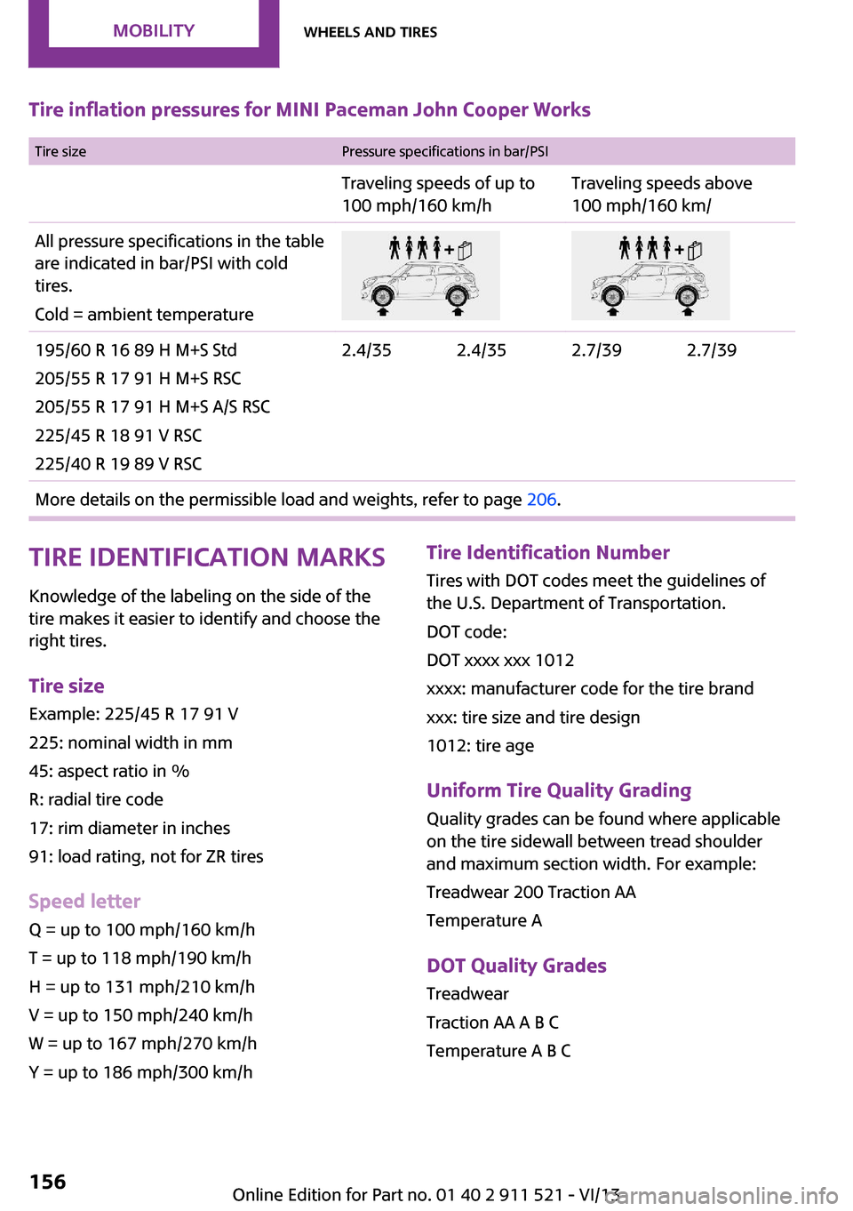
Tire inflation pressures for MINI Paceman John Cooper Works Tire sizePressure specifications in bar/PSITraveling speeds of up to
100 mph/160 km/hTraveling speeds above
100 mph/160 km/All pressure specifications in the table are indicated in bar/PSI with cold
tires.
Cold = ambient temperature195/60 R 16 89 H M+S Std
205/55 R 17 91 H M+S RSC
205/55 R 17 91 H M+S A/S RSC
225/45 R 18 91 V RSC
225/40 R 19 89 V RSC2.4/352.4/352.7/392.7/39More details on the permissible load and weights, refer to page 206.Tire identification marks
Knowledge of the labeling on the side of the tire makes it easier to identify and choose the
right tires.
Tire size Example: 225/45 R 17 91 V
225: nominal width in mm
45: aspect ratio in %
R: radial tire code
17: rim diameter in inches
91: load rating, not for ZR tires
Speed letter Q = up to 100 mph/160 km/h
T = up to 118 mph/190 km/h
H = up to 131 mph/210 km/h
V = up to 150 mph/240 km/h
W = up to 167 mph/270 km/h
Y = up to 186 mph/300 km/hTire Identification Number Tires with DOT codes meet the guidelines of
the U.S. Department of Transportation.
DOT code:
DOT xxxx xxx 1012
xxxx: manufacturer code for the tire brand
xxx: tire size and tire design
1012: tire age
Uniform Tire Quality Grading Quality grades can be found where applicable
on the tire sidewall between tread shoulder
and maximum section width. For example:
Treadwear 200 Traction AA
Temperature A
DOT Quality Grades
Treadwear
Traction AA A B C
Temperature A B CSeite 156MobilityWheels and tires156
Online Edition for Part no. 01 40 2 911 521 - VI/13
Page 159 of 218
Changing wheels and
tires
Mounting Information on mounting tires
Have mounting and balancing performed
only by a service center or tire specialist.
If this work is not carried out properly, there is
the danger of subsequent damage and related
safety hazards. ◀
Wheel and tire combination Information on the right wheel and tire combi‐
nation and rim version for your vehicle can be
obtained from the service center.
Incorrect wheel and tire combinations impair
the function of a variety of systems such as ABS
or DSC.
To maintain good handling and vehicle re‐
sponse, use only tires with a single tread con‐
figuration from a single manufacturer.
Following tire damage, have the original wheel
and tire combination remounted on the vehicle
as soon as possible.
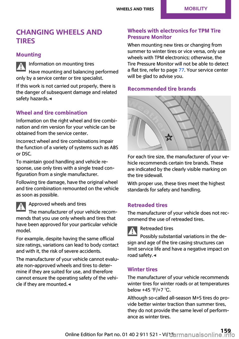
Approved wheels and tires
The manufacturer of your vehicle recom‐
mends that you use only wheels and tires that
have been approved for your particular vehicle
model.
For example, despite having the same official
size ratings, variations can lead to body contact
and with it, the risk of severe accidents.
The manufacturer of your vehicle cannot evalu‐
ate non-approved wheels and tires to deter‐
mine if they are suited for use, and therefore
cannot ensure the operating safety of the vehi‐
cle if they are mounted. ◀Wheels with electronics for TPM Tire
Pressure Monitor
When mounting new tires or changing from
summer to winter tires or vice versa, only use
wheels with TPM electronics; otherwise, the
Tire Pressure Monitor will not be able to detect
a flat tire, refer to page 77. Your service center
will be glad to advise you.
Recommended tire brands
For each tire size, the manufacturer of your ve‐
hicle recommends certain tire brands. These
are indicated by the clearly visible marking on
the tire sidewall.
With proper use, these tires meet the highest
standards for safety and handling.
Retreaded tires
The manufacturer of your vehicle does not rec‐
ommend the use of retreaded tires.
Retreaded tires
Possibly substantial variations in the de‐
sign and age of the tire casing structures can
limit service life and have a negative impact on
road safety. ◀
Winter tires The manufacturer of your vehicle recommends
winter tires for winter roads or at temperatures
below +45 ℉/+7 ℃.
Although so-called all-season M+S tires do pro‐
vide better winter traction than summer tires,
they do not provide the same level of perform‐
ance as winter tires.
Seite 159Wheels and tiresMobility159
Online Edition for Part no. 01 40 2 911 521 - VI/13
Page 161 of 218
▷If a warning triangle or portable hazard
warning lamp is required, set it up on the
roadside at an appropriate distance from
the rear of the vehicle. Comply with all
safety guidelines and regulations. ◀
The procedure to correct a flat tire depends on
the equipment in the vehicle:
▷Run-flat tires, refer to page 160.▷MINI Mobility System, refer to page 161.
MINI Mobility System
Notes
▷Follow the instructions on using the Mobi‐
lity System found on the compressor and
sealant bottle.▷Use of the Mobility System may be ineffec‐
tive if tire damage is greater than approx.
1/8 in/4 mm in size.▷Contact the nearest service center if the tire
cannot be made drivable.▷If possible, do not remove foreign bodies
that have penetrated the tire.▷Pull the speed limit sticker off the sealant
bottle and apply it to the steering wheel.
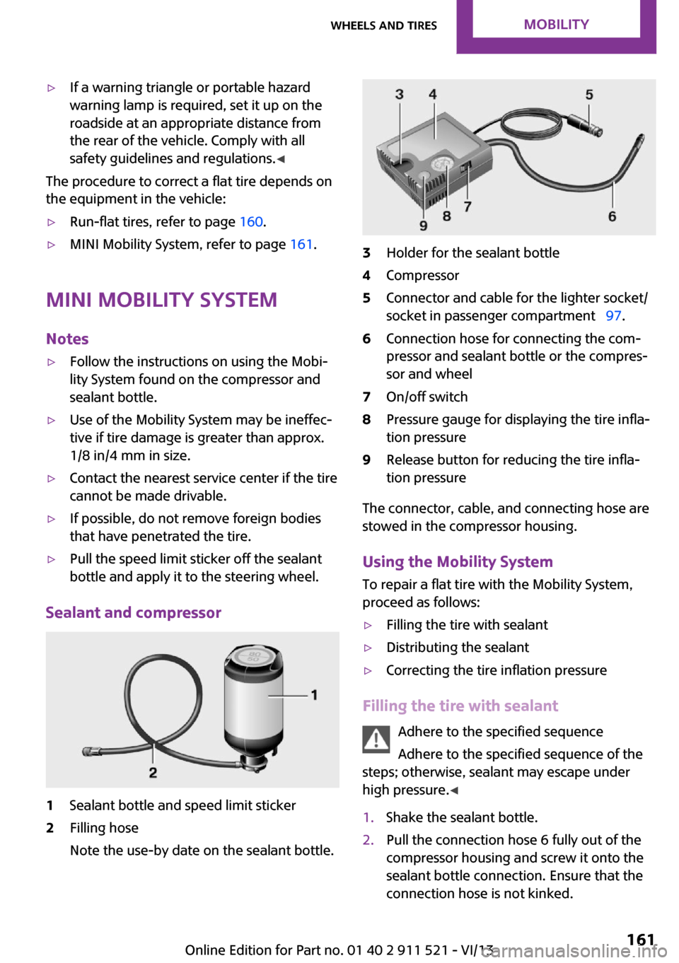
Sealant and compressor
1Sealant bottle and speed limit sticker2Filling hose
Note the use-by date on the sealant bottle.3Holder for the sealant bottle4Compressor5Connector and cable for the lighter socket/
socket in passenger compartment 97.6Connection hose for connecting the com‐
pressor and sealant bottle or the compres‐
sor and wheel7On/off switch8Pressure gauge for displaying the tire infla‐
tion pressure9Release button for reducing the tire infla‐
tion pressure
The connector, cable, and connecting hose are
stowed in the compressor housing.
Using the Mobility System
To repair a flat tire with the Mobility System,
proceed as follows:
▷Filling the tire with sealant▷Distributing the sealant▷Correcting the tire inflation pressure
Filling the tire with sealant
Adhere to the specified sequence
Adhere to the specified sequence of the
steps; otherwise, sealant may escape under
high pressure. ◀
1.Shake the sealant bottle.2.Pull the connection hose 6 fully out of the
compressor housing and screw it onto the
sealant bottle connection. Ensure that the
connection hose is not kinked.Seite 161Wheels and tiresMobility161
Online Edition for Part no. 01 40 2 911 521 - VI/13
Page 163 of 218
Do not allow the compressor to run too
long
Do not allow the compressor to run longer than
10 minutes; otherwise, the device will overheat
and may be damaged. ◀
If the inflation pressure is not maintained, take
the vehicle on another drive, distributing the
sealant, refer to page 162. Then repeat steps
1 to 4 once.
If the inflation pressure of 1.8 bar/26 psi is still
not reached, the tire is too heavily damaged.
Contact the nearest service center.
Continuing the trip Note the maximum speed
Do not exceed the maximum speed of
50 mph/80 km/h; otherwise, accidents can oc‐
cur. ◀
Replace the defective tire as soon as possible
and have the wheel balanced.
Have the Mobility System refilled.
Snow chains
Only certain fine-link snow chains have been
tested by MINI, classified as safe for use, and
recommended. Consult your service center for more information.
Use only in pairs on the front wheels, equipped
with tires of the following size:
195/60 R 16 M+S
With ALL4 all-wheel drive: only mount snow
chains on the front wheels.
Observe the manufacturer's instructions when
mounting snow chains. Do not exceed a speed
of 30 mph or 50 km/h when using snow chains.
Do not initialize the Flat Tire Monitor if snow
chains are mounted; otherwise, the instrument
might issue an incorrect reading. When driving
with snow chains, it may be useful to tempora‐rily deactivate DSC or activate DTC, refer to
page 81.Seite 163Wheels and tiresMobility163
Online Edition for Part no. 01 40 2 911 521 - VI/13
Page 215 of 218
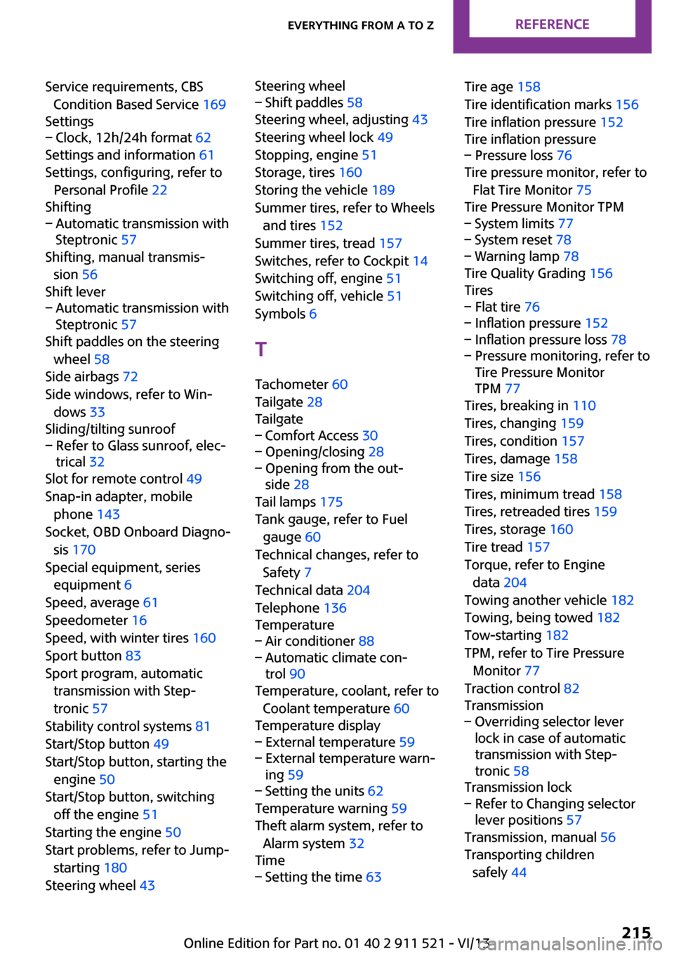
Service requirements, CBSCondition Based Service 169
Settings– Clock, 12h/24h format 62
Settings and information 61
Settings, configuring, refer to Personal Profile 22
Shifting
– Automatic transmission with
Steptronic 57
Shifting, manual transmis‐
sion 56
Shift lever
– Automatic transmission with
Steptronic 57
Shift paddles on the steering
wheel 58
Side airbags 72
Side windows, refer to Win‐ dows 33
Sliding/tilting sunroof
– Refer to Glass sunroof, elec‐
trical 32
Slot for remote control 49
Snap-in adapter, mobile phone 143
Socket, OBD Onboard Diagno‐ sis 170
Special equipment, series equipment 6
Speed, average 61
Speedometer 16
Speed, with winter tires 160
Sport button 83
Sport program, automatic transmission with Step‐
tronic 57
Stability control systems 81
Start/Stop button 49
Start/Stop button, starting the engine 50
Start/Stop button, switching off the engine 51
Starting the engine 50
Start problems, refer to Jump- starting 180
Steering wheel 43
Steering wheel– Shift paddles 58
Steering wheel, adjusting 43
Steering wheel lock 49
Stopping, engine 51
Storage, tires 160
Storing the vehicle 189
Summer tires, refer to Wheels and tires 152
Summer tires, tread 157
Switches, refer to Cockpit 14
Switching off, engine 51
Switching off, vehicle 51
Symbols 6
T Tachometer 60
Tailgate 28
Tailgate
– Comfort Access 30– Opening/closing 28– Opening from the out‐
side 28
Tail lamps 175
Tank gauge, refer to Fuel gauge 60
Technical changes, refer to Safety 7
Technical data 204
Telephone 136
Temperature
– Air conditioner 88– Automatic climate con‐
trol 90
Temperature, coolant, refer to
Coolant temperature 60
Temperature display
– External temperature 59– External temperature warn‐
ing 59– Setting the units 62
Temperature warning 59
Theft alarm system, refer to Alarm system 32
Time
– Setting the time 63Tire age 158
Tire identification marks 156
Tire inflation pressure 152
Tire inflation pressure– Pressure loss 76
Tire pressure monitor, refer to
Flat Tire Monitor 75
Tire Pressure Monitor TPM
– System limits 77– System reset 78– Warning lamp 78
Tire Quality Grading 156
Tires
– Flat tire 76– Inflation pressure 152– Inflation pressure loss 78– Pressure monitoring, refer to
Tire Pressure Monitor
TPM 77
Tires, breaking in 110
Tires, changing 159
Tires, condition 157
Tires, damage 158
Tire size 156
Tires, minimum tread 158
Tires, retreaded tires 159
Tires, storage 160
Tire tread 157
Torque, refer to Engine data 204
Towing another vehicle 182
Towing, being towed 182
Tow-starting 182
TPM, refer to Tire Pressure Monitor 77
Traction control 82
Transmission
– Overriding selector lever
lock in case of automatic
transmission with Step‐
tronic 58
Transmission lock
– Refer to Changing selector
lever positions 57
Transmission, manual 56
Transporting children safely 44
Seite 215Everything from A to ZReference215
Online Edition for Part no. 01 40 2 911 521 - VI/13