battery MINI Paceman 2015 User Guide
[x] Cancel search | Manufacturer: MINI, Model Year: 2015, Model line: Paceman, Model: MINI Paceman 2015Pages: 223, PDF Size: 5.51 MB
Page 71 of 223

Depending on the steering angle and other pa‐
rameters, the light from the headlight follows
the course of the road.
Activating With the ignition switch on, turn the light switch
to position 3, refer to page 66.
To avoid blinding oncoming traffic, the Adap‐
tive Light Control does not swivel to the driver's
side when the vehicle is at a standstill.
When driving in reverse, Adaptive Light Control
is not active.
Malfunction The warning light lights up. Adaptive
Light Control is malfunctioning or has
failed. Have the system checked as
soon as possible.
More information, refer to page 191.
Fog lights
At a glance
To switch on the front fog lights: press the
switch.
To switch off, press the respective switch up‐
ward or downward again.
Fog lights The parking lights or low beams must be
switched on. The green indicator lamp lights up
when the front fog lights are switched on.
Depending on the vehicle equipment, the front
fog lights are switched off when the headlight
flasher or the high-beams are activated.
If the automatic headlight control is activated,
refer to page 66, the low beams are switched
on automatically when the front fog lights are
switched on.
Instrument lighting
The parking lights or low beams must be
switched on to adjust the brightness. The
brightness is increased to a certain limit and is then reduced again.▷Press the button briefly: the brightness
changes in stages.▷Press and hold the button: the brightness
changes continuously.
Interior lights
The interior lights, the footwell lights and thecargo area light are controlled automatically.
To avoid draining the battery, all lights inside
the vehicle are switched off some time after the
ignition is switched off.
Seite 69LampsCONTROLS69
Online Edition for Part no. 01 40 2 961 084 - II/15
Page 91 of 223
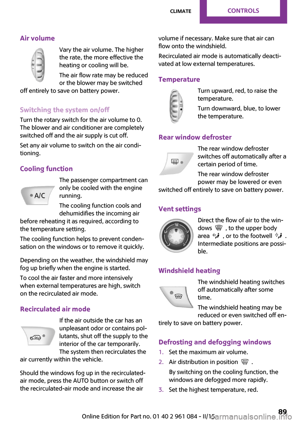
Air volumeVary the air volume. The higher
the rate, the more effective the
heating or cooling will be.
The air flow rate may be reduced
or the blower may be switched
off entirely to save on battery power.
Switching the system on/off
Turn the rotary switch for the air volume to 0.
The blower and air conditioner are completely
switched off and the air supply is cut off.
Set any air volume to switch on the air condi‐
tioning.
Cooling function The passenger compartment can
only be cooled with the engine
running.
The cooling function cools and
dehumidifies the incoming air
before reheating it as required, according to
the temperature setting.
The cooling function helps to prevent conden‐
sation on the windows or to remove it quickly.
Depending on the weather, the windshield may
fog up briefly when the engine is started.
To cool the air faster and more intensively
when external temperatures are high, switch
on the recirculated air mode.
Recirculated air mode If the air outside the car has an
unpleasant odor or contains pol‐
lutants, shut off the supply to the
interior of the car temporarily.
The system then recirculates the
air currently within the vehicle.
Should the windows fog up in the recirculated-
air mode, press the AUTO button or switch off
the recirculated-air mode and increase the airvolume if necessary. Make sure that air can
flow onto the windshield.
Recirculated air mode is automatically deacti‐
vated at low external temperatures.
Temperature Turn upward, red, to raise thetemperature.
Turn downward, blue, to lower
the temperature.
Rear window defroster The rear window defroster
switches off automatically after a
certain period of time.
The rear window defroster
power may be lowered or even
switched off entirely to save on battery power.
Vent settings Direct the flow of air to the win‐
dows
, to the upper body
area
, or to the footwell .
Intermediate positions are possi‐
ble.
Windshield heating The windshield heating switches
off automatically after some
time.
The windshield heating may be
reduced or even switched off en‐
tirely to save on battery power.
Defrosting and defogging windows
1.Set the maximum air volume.2.Air distribution in position .
By switching on the cooling function, the
windows are defogged more rapidly.3.Set the highest temperature, red.Seite 89ClimateCONTROLS89
Online Edition for Part no. 01 40 2 961 084 - II/15
Page 93 of 223
NotesSufficient ventilation
When remaining in the vehicle for an ex‐
tended period of time, ensure sufficient exter‐
nal ventilation. Do not continuously use recircu‐
lated-air mode; otherwise the air quality in the
interior continuously worsens. ◀
Comfortable interior climate The AUTO program offers the optimum air dis‐
tribution and air volume for virtually all condi‐
tions, refer to AUTO program below. Select a
comfortable interior temperature only.
The following sections contain more detailed
information on the available setting options.
Most of these settings are stored for the remote
control in use, Personal Profile settings, refer to
page 21.
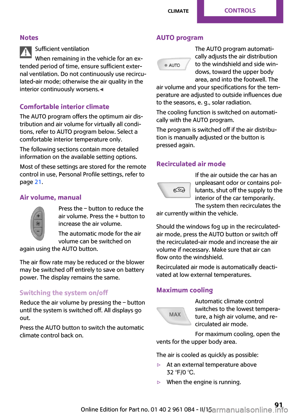
Air volume, manual Press the – button to reduce the
air volume. Press the + button to
increase the air volume.
The automatic mode for the air
volume can be switched on
again using the AUTO button.
The air flow rate may be reduced or the blower
may be switched off entirely to save on battery
power. The display remains the same.
Switching the system on/off Reduce the air volume by pressing the – button
until the system is switched off. All displays go
out.
Press the AUTO button to switch the automatic
climate control back on.AUTO program
The AUTO program automati‐
cally adjusts the air distribution
to the windshield and side win‐
dows, toward the upper body
area, and into the footwell. The
air volume and your specifications for the tem‐
perature are adjusted to outside influences due
to the seasons, e. g., solar radiation.
The cooling function is switched on automati‐
cally with the AUTO program.
The program is switched off if the air distribu‐
tion is manually adjusted or the button is
pressed again.
Recirculated air mode If the air outside the car has an
unpleasant odor or contains pol‐
lutants, shut off the supply to the
interior of the car temporarily.
The system then recirculates the
air currently within the vehicle.
Should the windows fog up in the recirculated-
air mode, press the AUTO button or switch off
the recirculated-air mode and increase the air
volume if necessary. Make sure that air can
flow onto the windshield.
Recirculated air mode is automatically deacti‐
vated at low external temperatures.
Maximum cooling Automatic climate control
switches to the lowest tempera‐
ture, a high air volume, and re‐
circulated air mode.
For maximum cooling, open the
vents for the upper body area.
The air is cooled as quickly as possible:▷At an external temperature above
32 ℉/0 ℃.▷When the engine is running.Seite 91ClimateCONTROLS91
Online Edition for Part no. 01 40 2 961 084 - II/15
Page 101 of 223
The lighter can be removed as soon as it pops
back out.
Danger of burns
Only hold the hot lighter by its head; oth‐
erwise, there is the danger of getting burned.
Switch off the ignition and take the remote
control with you when leaving the vehicle so
that children cannot use the lighter and burn
themselves. ◀
Connecting electrical de‐
vices
The lighter socket can be used as a socket for
electrical equipment while the engine is run‐
ning or when the ignition is switched on. The
total load of all sockets must not exceed
140 watts at 12 volt.
Avoid damaging the sockets by attempting to
insert plugs of unsuitable shape or size.
Do not connect the charger to the socket
Do not connect the battery charger to the
socket installed in the vehicle at the factory as this could damage the battery. ◀
Replace the cover after use
Replace the lighter or socket cover after
use; otherwise, objects that fall into the lighter
socket or power socket could cause a short cir‐
cuit. ◀
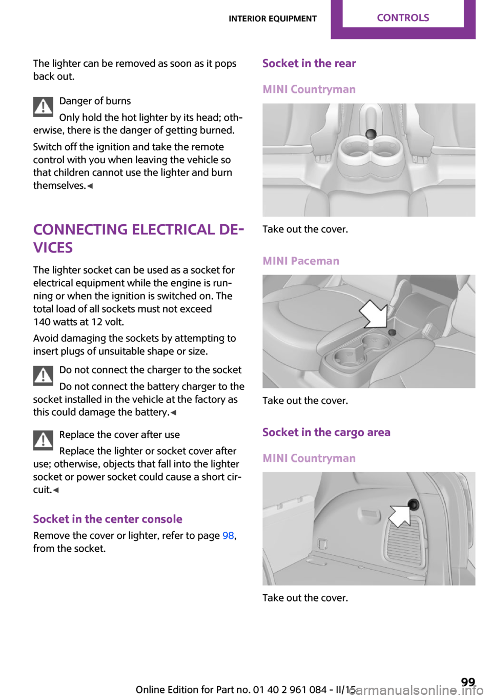
Socket in the center console
Remove the cover or lighter, refer to page 98,
from the socket.Socket in the rear
MINI Countryman
Take out the cover.
MINI Paceman
Take out the cover.
Socket in the cargo area
MINI Countryman
Take out the cover.
Seite 99Interior equipmentCONTROLS99
Online Edition for Part no. 01 40 2 961 084 - II/15
Page 126 of 223
for approx. 20 minutes. To listen to the radio,
switch it back on.
To spare the battery, ensure that the radio is
switched off when you leave the vehicle.
Adjusting the volume Turn the left knob. The setting is stored for the
remote control currently in use.
When a call is placed using the hands-free sys‐
tem, the audio sources are muted.
Speed-dependent volume and volumes
of PDC signal tone and gong▷"PDC": volume of the PDC signal tone com‐
pared to the audio sources.▷"GONG": volume of the gong compared to
the audio sources.▷"S-VOL": speed-dependent volume control.
Set the audio sources to a high volume to be
able to adjust the volume of the signal tones
more easily.
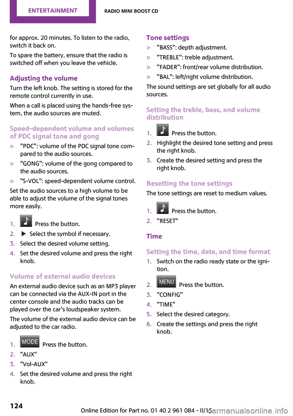
1. Press the button.2. Select the symbol if necessary.3.Select the desired volume setting.4.Set the desired volume and press the right
knob.
Volume of external audio devices
An external audio device such as an MP3 player
can be connected via the AUX-IN port in the
center console and the audio tracks can be
played over the car's loudspeaker system.
The volume of the external audio device can be
adjusted to the car radio.
1. Press the button.2."AUX"3."Vol-AUX"4.Set the desired volume and press the right
knob.Tone settings▷"BASS": depth adjustment.▷"TREBLE": treble adjustment.▷"FADER": front/rear volume distribution.▷"BAL": left/right volume distribution.
The sound settings are set globally for all audio
sources.
Setting the treble, bass, and volume distribution
1. Press the button.2.Highlight the desired tone setting and press
the right knob.3.Create the desired setting and press the
right knob.
Resetting the tone settings
The tone settings are reset to medium values.
1. Press the button.2."RESET"
Time
Setting the time, date, and time format
1.Switch on the radio ready state or the igni‐
tion.2. Press the button.3."CONFIG"4."TIME"5.Select the desired category.6.Create the settings and press the right
knob.Seite 124ENTERTAINMENTRadio MINI Boost CD124
Online Edition for Part no. 01 40 2 961 084 - II/15
Page 138 of 223
TelephoneVehicle equipment
This chapter describes all series equipment as
well as country-specific and special equipment
offered for this model series. Therefore, it also
describes equipment that may not be found in
your vehicle, for instance due to the selected
special equipment or the country version. This
also applies to safety-related functions and sys‐
tems.
When using the features and systems described
here, adhere to local regulations.
At a glance
The concept
Mobile phones can be connected with the vehi‐
cle via Bluetooth.
After a suitable mobile phone is paired with the
vehicle once, you can operate the mobile
phone via the radio, the buttons on the steer‐
ing wheel, and via voice activation.
Bluetooth® is a registered trademark of Blue‐
tooth® SIG, Inc.
Certain functions may need to be enabled by
the mobile phone provider or service provider.
Using the mobile phone while driving
Make entries only when traffic and road
conditions allow. Do not hold the mobile phone
in your hand while you are driving; use the
hands-free system instead. If you do not ob‐
serve this precaution, you can endanger the ve‐
hicle occupants and other road users. ◀
Snap-in adapter
The snap-in adapter is used to:▷Hold the mobile phone.▷Recharge the battery.▷Connect the mobile phone to an outside
antenna of the vehicle.
This provides for better network reception
and consistent sound quality.
Do not operate a mobile phone that is con‐
nected to the vehicle on the mobile phone key‐
pad, as this may lead to a malfunction.
Approved mobile phones
Details on which mobile phones with a Blue‐
tooth interface are supported by the mobile
phone preparation package can be obtained at
www.mini.com/connectivity.
Notes At high temperatures, the charging function of
the mobile phone may be limited and functions
may not be executed.
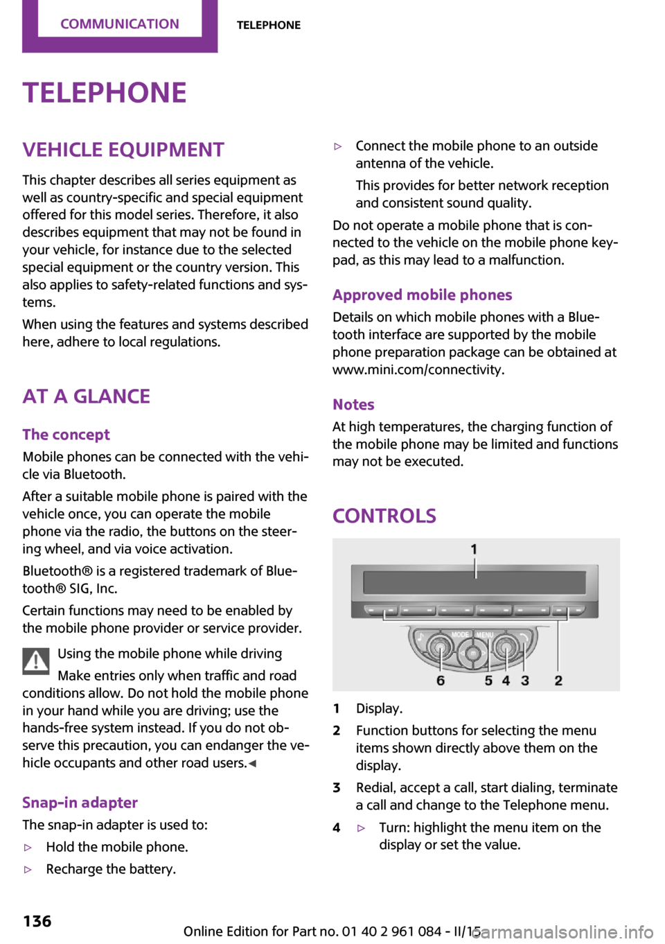
Controls
1Display.2Function buttons for selecting the menu
items shown directly above them on the
display.3Redial, accept a call, start dialing, terminate
a call and change to the Telephone menu.4▷Turn: highlight the menu item on the
display or set the value.Seite 136COMMUNICATIONTelephone136
Online Edition for Part no. 01 40 2 961 084 - II/15
Page 146 of 223
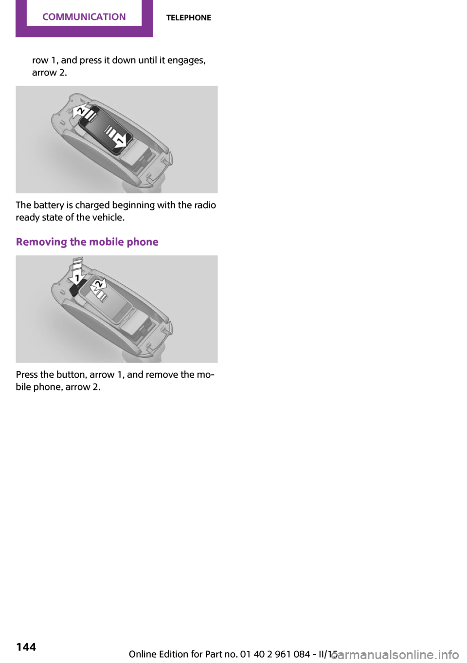
row 1, and press it down until it engages,
arrow 2.
The battery is charged beginning with the radio
ready state of the vehicle.
Removing the mobile phone
Press the button, arrow 1, and remove the mo‐
bile phone, arrow 2.
Seite 144COMMUNICATIONTelephone144
Online Edition for Part no. 01 40 2 961 084 - II/15
Page 166 of 223
Engine compartmentVehicle equipment
This chapter describes all series equipment as
well as country-specific and special equipment
offered for this model series. Therefore, it also
describes equipment that may not be found in
your vehicle, for instance due to the selectedspecial equipment or the country version. This
also applies to safety-related functions and sys‐
tems.
When using the features and systems described
here, adhere to local regulations.
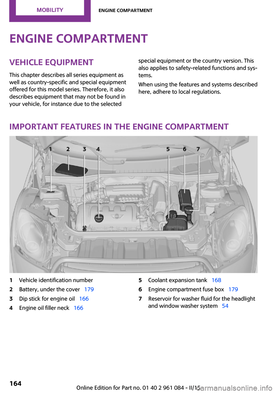
Important features in the engine compartment
1Vehicle identification number2Battery, under the cover 1793Dip stick for engine oil 1664Engine oil filler neck 1665Coolant expansion tank 1686Engine compartment fuse box 1797Reservoir for washer fluid for the headlight
and window washer system 54Seite 164MOBILITYEngine compartment164
Online Edition for Part no. 01 40 2 961 084 - II/15
Page 181 of 223
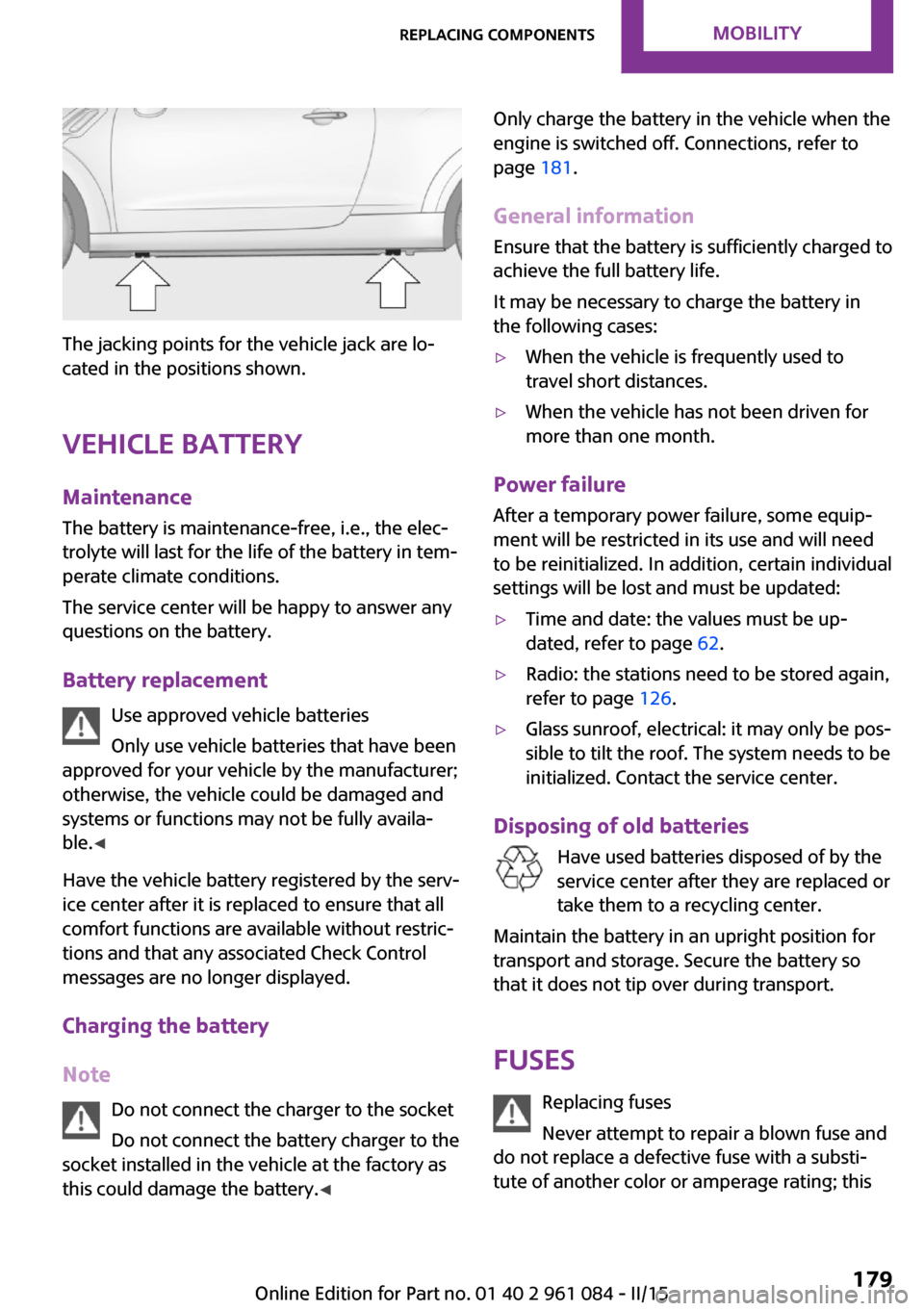
The jacking points for the vehicle jack are lo‐
cated in the positions shown.
Vehicle battery Maintenance
The battery is maintenance-free, i.e., the elec‐
trolyte will last for the life of the battery in tem‐
perate climate conditions.
The service center will be happy to answer any
questions on the battery.
Battery replacement Use approved vehicle batteries
Only use vehicle batteries that have been
approved for your vehicle by the manufacturer;
otherwise, the vehicle could be damaged and
systems or functions may not be fully availa‐
ble. ◀
Have the vehicle battery registered by the serv‐
ice center after it is replaced to ensure that all
comfort functions are available without restric‐
tions and that any associated Check Control
messages are no longer displayed.
Charging the battery
Note Do not connect the charger to the socket
Do not connect the battery charger to the
socket installed in the vehicle at the factory as this could damage the battery. ◀
Only charge the battery in the vehicle when the
engine is switched off. Connections, refer to
page 181.
General information Ensure that the battery is sufficiently charged to
achieve the full battery life.
It may be necessary to charge the battery in
the following cases:▷When the vehicle is frequently used to
travel short distances.▷When the vehicle has not been driven for
more than one month.
Power failure
After a temporary power failure, some equip‐
ment will be restricted in its use and will need
to be reinitialized. In addition, certain individual
settings will be lost and must be updated:
▷Time and date: the values must be up‐
dated, refer to page 62.▷Radio: the stations need to be stored again,
refer to page 126.▷Glass sunroof, electrical: it may only be pos‐
sible to tilt the roof. The system needs to be
initialized. Contact the service center.
Disposing of old batteries
Have used batteries disposed of by the
service center after they are replaced or
take them to a recycling center.
Maintain the battery in an upright position for
transport and storage. Secure the battery so
that it does not tip over during transport.
Fuses Replacing fuses
Never attempt to repair a blown fuse and
do not replace a defective fuse with a substi‐
tute of another color or amperage rating; this
Seite 179Replacing componentsMOBILITY179
Online Edition for Part no. 01 40 2 961 084 - II/15
Page 183 of 223
Breakdown assistanceVehicle equipment
This chapter describes all series equipment as
well as country-specific and special equipment
offered for this model series. Therefore, it also
describes equipment that may not be found in
your vehicle, for instance due to the selected
special equipment or the country version. This
also applies to safety-related functions and sys‐
tems.
When using the features and systems described
here, adhere to local regulations.
Hazard warning flash‐
ers
The button is located on the speedometer.
Warning triangle
Under the loading edge in the cargo area.
To remove, open the two fasteners.
First aid kit Some of the articles contained in the first aid kit
have a limited service life. Therefore, check the
use-by dates of the contents regularly and re‐
place the items before they expire.
The first aid kit is located in the left side trim on
the cargo area floor or under the loading floor.
Roadside Assistance Service availability
Roadside Assistance can be reached around the
clock in many countries. You can obtain assis‐
tance there in the event of a vehicle break‐
down.
Roadside Assistance A phone number for Roadside Assistance can
be displayed, refer to page 142, via the radio.
Jump-starting NotesIf the battery is discharged, the engine can be
started using the battery of another vehicle and
Seite 181Breakdown assistanceMOBILITY181
Online Edition for Part no. 01 40 2 961 084 - II/15