warning lights MINI Paceman 2015 User Guide
[x] Cancel search | Manufacturer: MINI, Model Year: 2015, Model line: Paceman, Model: MINI Paceman 2015Pages: 223, PDF Size: 5.51 MB
Page 77 of 223
Do not initialize the system when driving with
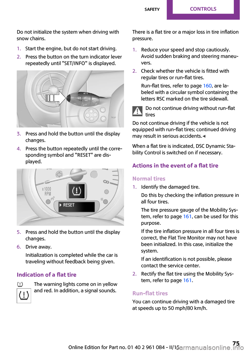
snow chains.1.Start the engine, but do not start driving.2.Press the button on the turn indicator lever
repeatedly until "SET/INFO" is displayed.3.Press and hold the button until the display
changes.4.Press the button repeatedly until the corre‐
sponding symbol and "RESET" are dis‐
played.5.Press and hold the button until the display
changes.6.Drive away.
Initialization is completed while the car is
traveling without feedback being given.
Indication of a flat tire
The warning lights come on in yellow
and red. In addition, a signal sounds.
There is a flat tire or a major loss in tire inflation
pressure.1.Reduce your speed and stop cautiously.
Avoid sudden braking and steering maneu‐
vers.2.Check whether the vehicle is fitted with
regular tires or run-flat tires.
Run-flat tires, refer to page 160, are la‐
beled with a circular symbol containing the
letters RSC marked on the tire sidewall.
Do not continue driving without run-flat
tires
Do not continue driving if the vehicle is not
equipped with run-flat tires; continued driving
may result in serious accidents. ◀
When a flat tire is indicated, DSC Dynamic Sta‐
bility Control is switched on if necessary.
Actions in the event of a flat tire
Normal tires
1.Identify the damaged tire.
Do this by checking the inflation pressure in
all four tires.
The tire pressure gauge of the Mobility Sys‐
tem, refer to page 161, can be used for this
purpose.
If the tire inflation pressure in all four tires is
correct, the Flat Tire Monitor may not have
been initialized. In this case, initialize the
system.
If an identification is not possible, please
contact the service center.2.Rectify the flat tire using the Mobility Sys‐
tem, refer to page 161.
Run-flat tires
You can continue driving with a damaged tire
at speeds up to 50 mph/80 km/h.
Seite 75SafetyCONTROLS75
Online Edition for Part no. 01 40 2 961 084 - II/15
Page 79 of 223
Performing a reset
Perform a system reset after adjusting the tire
inflation pressure to a new value and after
changing a tire or wheel.1.Start the engine, but do not start driving.2.Press the button on the turn indicator lever
repeatedly until "SET/INFO" is displayed.3.Press and hold the button until the display
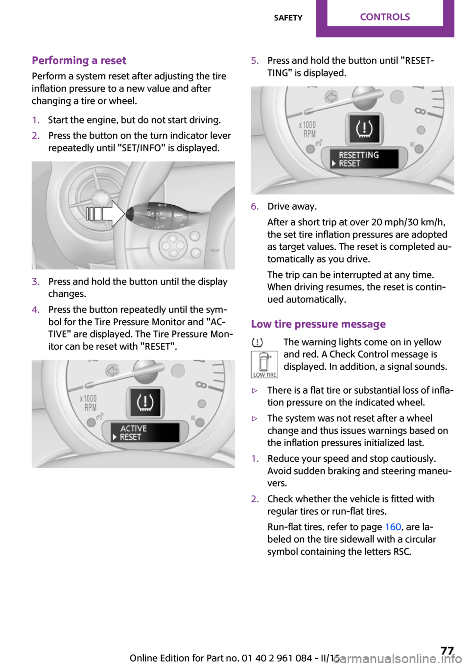
changes.4.Press the button repeatedly until the sym‐
bol for the Tire Pressure Monitor and "AC‐
TIVE" are displayed. The Tire Pressure Mon‐
itor can be reset with "RESET".5.Press and hold the button until "RESET‐
TING" is displayed.6.Drive away.
After a short trip at over 20 mph/30 km/h,
the set tire inflation pressures are adopted
as target values. The reset is completed au‐
tomatically as you drive.
The trip can be interrupted at any time.
When driving resumes, the reset is contin‐
ued automatically.
Low tire pressure message
The warning lights come on in yellow
and red. A Check Control message is
displayed. In addition, a signal sounds.
▷There is a flat tire or substantial loss of infla‐
tion pressure on the indicated wheel.▷The system was not reset after a wheel
change and thus issues warnings based on
the inflation pressures initialized last.1.Reduce your speed and stop cautiously.
Avoid sudden braking and steering maneu‐
vers.2.Check whether the vehicle is fitted with
regular tires or run-flat tires.
Run-flat tires, refer to page 160, are la‐
beled on the tire sidewall with a circular
symbol containing the letters RSC.Seite 77SafetyCONTROLS77
Online Edition for Part no. 01 40 2 961 084 - II/15
Page 81 of 223
Final tire failure
Vibrations or loud noises while driving
can indicate the final failure of the tire. Reduce
speed and stop; otherwise, pieces of the tire
could come loose and cause an accident. Do
not continue driving, and contact your service
center. ◀
Message indicating that the inflation
pressure needs to be checked
The yellow warning light lights up.
A Check Control message is displayed.▷The system has detected that a wheel was
changed but a reset was not performed.▷The tire was not inflated according to speci‐
fications.▷The tire pressure has dropped since the last
confirmation.
In this case:
▷Check the tire inflation pressure and correct
it if necessary.▷After changing a wheel, reset the system.
System limits
The system will not function properly if a reset
was not performed, e.g., it may identify a tire as
flat although the tire is filled to the correct infla‐
tion pressure.
The tire pressure depends on the temperature
of the tire. An increase in the tire temperature,
e.g., while driving or due to sunlight, increases
the tire inflation pressure. The tire pressure de‐
creases when the tire temperature drops. In
case of severe temperature drops, this behavior
may lead to a warning on account of the de‐
fined warning limits.
Malfunction The yellow warning light flashes yellow
and then lights up continuously.
A Check Control message is displayed.
A flat tire or tire inflation pressure loss cannot
be detected.
Display in the following situations:▷A wheel without TPM electronics is
mounted, e.g., a compact wheel:
Have the system checked by the service
center if necessary.▷Malfunction:
Have the system checked by the service
center.▷TPM was unable to complete the reset.
Reset the system again.
The yellow warning light flashes and
then lights up continuously.
A Check Control message is displayed.
A flat tire or tire inflation pressure loss cannot
be detected.
Display in the following situation:
▷Disturbance by other systems or devices
with the same radio frequency:
After leaving the area of the disturbance,
the system automatically becomes active
again.
Declaration according to NHTSA/FMVSS
138 Tire Pressure Monitoring Systems
Each tire, including the spare (if provided)
should be checked monthly when cold and in‐
flated to the inflation pressure recommended
by the vehicle manufacturer on the vehicle
placard or tire inflation pressure label (If your
vehicle has tires of a different size than the size indicated on the vehicle placard or tire inflation
pressure label, you should determine the
proper tire inflation pressure for those tires.).
As an added safety feature, your vehicle has
been equipped with a tire pressure monitoring
system (TPMS) that illuminates a low tire pres‐
sure telltale when one or more of your tires is
significantly under-inflated. Accordingly, when
the low tire pressure telltale illuminates, you
Seite 79SafetyCONTROLS79
Online Edition for Part no. 01 40 2 961 084 - II/15
Page 84 of 223
Deactivating DSC
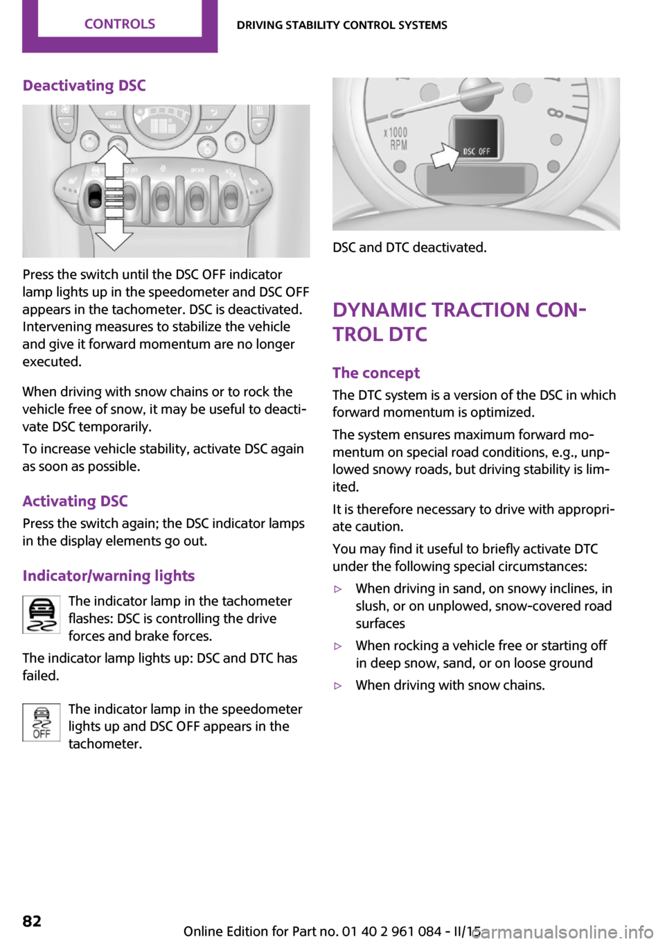
Press the switch until the DSC OFF indicator
lamp lights up in the speedometer and DSC OFF
appears in the tachometer. DSC is deactivated.
Intervening measures to stabilize the vehicle
and give it forward momentum are no longer
executed.
When driving with snow chains or to rock the
vehicle free of snow, it may be useful to deacti‐
vate DSC temporarily.
To increase vehicle stability, activate DSC again
as soon as possible.
Activating DSC
Press the switch again; the DSC indicator lamps
in the display elements go out.
Indicator/warning lights The indicator lamp in the tachometer
flashes: DSC is controlling the drive
forces and brake forces.
The indicator lamp lights up: DSC and DTC has
failed.
The indicator lamp in the speedometer
lights up and DSC OFF appears in the
tachometer.
DSC and DTC deactivated.
Dynamic Traction Con‐
trol DTC
The concept
The DTC system is a version of the DSC in which
forward momentum is optimized.
The system ensures maximum forward mo‐
mentum on special road conditions, e.g., unp‐
lowed snowy roads, but driving stability is lim‐
ited.
It is therefore necessary to drive with appropri‐
ate caution.
You may find it useful to briefly activate DTC
under the following special circumstances:
▷When driving in sand, on snowy inclines, in
slush, or on unplowed, snow-covered road
surfaces▷When rocking a vehicle free or starting off
in deep snow, sand, or on loose ground▷When driving with snow chains.Seite 82CONTROLSDriving stability control systems82
Online Edition for Part no. 01 40 2 961 084 - II/15
Page 85 of 223
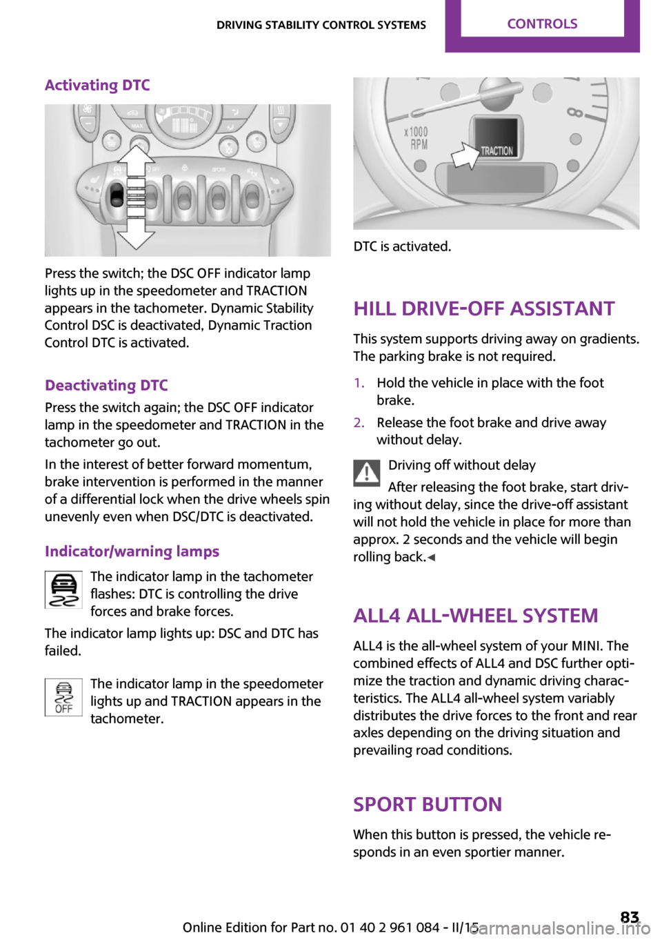
Activating DTC
Press the switch; the DSC OFF indicator lamp
lights up in the speedometer and TRACTION
appears in the tachometer. Dynamic Stability
Control DSC is deactivated, Dynamic Traction
Control DTC is activated.
Deactivating DTC Press the switch again; the DSC OFF indicator
lamp in the speedometer and TRACTION in the
tachometer go out.
In the interest of better forward momentum,
brake intervention is performed in the manner
of a differential lock when the drive wheels spin
unevenly even when DSC/DTC is deactivated.
Indicator/warning lamps The indicator lamp in the tachometer
flashes: DTC is controlling the drive
forces and brake forces.
The indicator lamp lights up: DSC and DTC has
failed.
The indicator lamp in the speedometer
lights up and TRACTION appears in the
tachometer.
DTC is activated.
Hill drive-off assistant This system supports driving away on gradients.
The parking brake is not required.
1.Hold the vehicle in place with the foot
brake.2.Release the foot brake and drive away
without delay.
Driving off without delay
After releasing the foot brake, start driv‐
ing without delay, since the drive-off assistant
will not hold the vehicle in place for more than
approx. 2 seconds and the vehicle will begin
rolling back. ◀
ALL4 all-wheel system
ALL4 is the all-wheel system of your MINI. The
combined effects of ALL4 and DSC further opti‐
mize the traction and dynamic driving charac‐
teristics. The ALL4 all-wheel system variably
distributes the drive forces to the front and rear
axles depending on the driving situation and
prevailing road conditions.
Sport button When this button is pressed, the vehicle re‐
sponds in an even sportier manner.
Seite 83Driving stability control systemsCONTROLS83
Online Edition for Part no. 01 40 2 961 084 - II/15
Page 88 of 223
▷The transmission position D is disengaged.▷DSC intervenes.
Maintaining, storing the current speedPress button 1 or button 3.
The current speed is maintained and stored. It
is displayed briefly in the tachometer.
On downhill gradients, it may prove impossible
to maintain the set speed if the engine braking
power is insufficient. On uphill gradients, it may
prove impossible to maintain the set speed if
the engine power output is insufficient.
Increasing speed
▷Press button 1 repeatedly until the desired
speed is reached.
Each time the button is pressed, the speed
increases by approx. 1 mph/1 km/h.▷Press and hold button 1 until the desired
speed is reached.
The vehicle accelerates without pressure on
the accelerator pedal. After the button is
released, the achieved speed is maintained
and stored.
Decreasing speed
Press button 3 repeatedly or hold it until the
desired speed is reached.
The functions are the same those when the
speed is increased, only that the speed is re‐
duced.
Resuming a speed stored beforehand Press button 4.
The last stored speed is resumed and main‐
tained.
The stored speed is cleared when the ignition is
switched off.
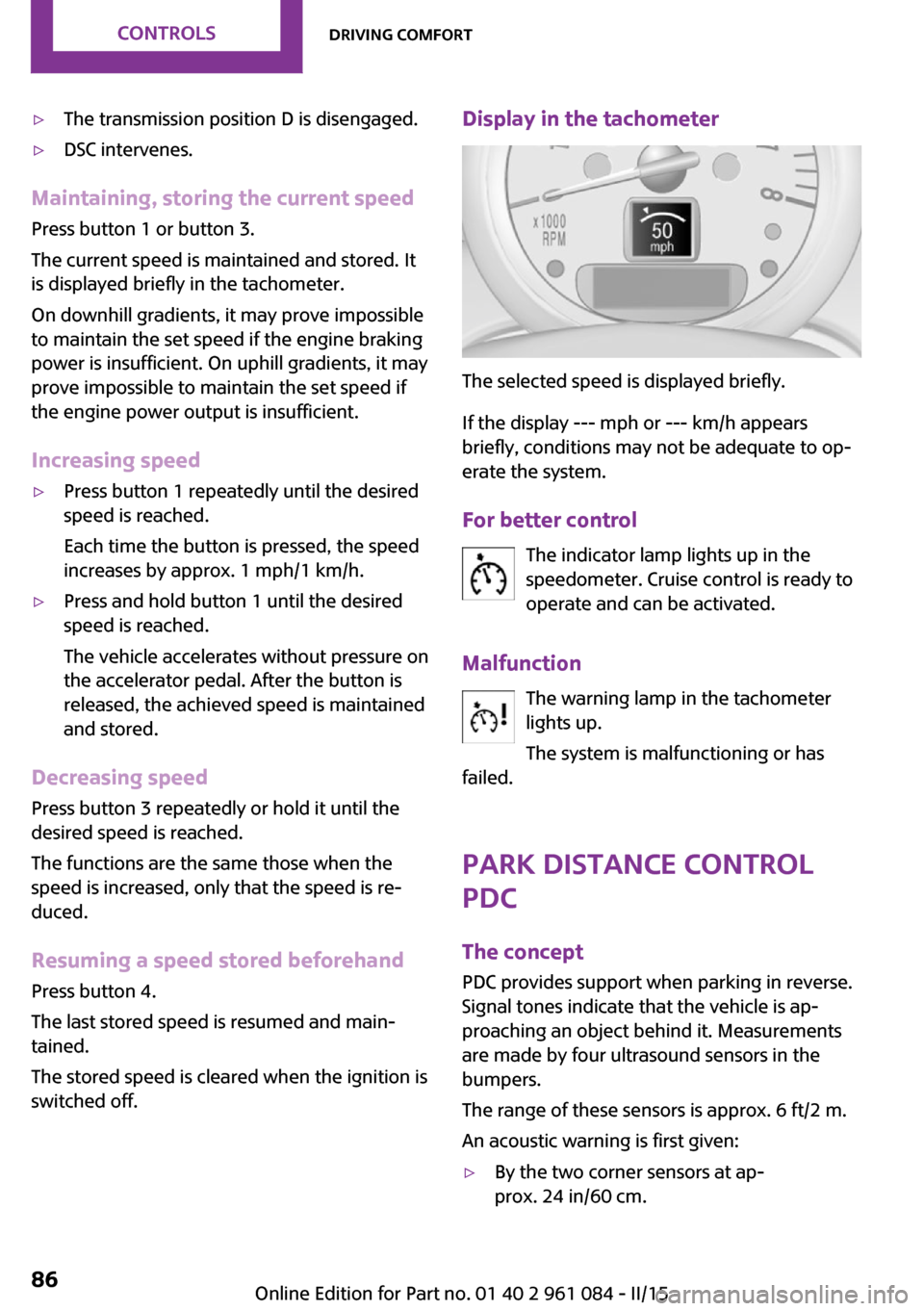
Display in the tachometer
The selected speed is displayed briefly.
If the display --- mph or --- km/h appears
briefly, conditions may not be adequate to op‐
erate the system.
For better control The indicator lamp lights up in the
speedometer. Cruise control is ready to
operate and can be activated.
Malfunction The warning lamp in the tachometer
lights up.
The system is malfunctioning or has
failed.
Park Distance Control
PDC
The concept
PDC provides support when parking in reverse.
Signal tones indicate that the vehicle is ap‐
proaching an object behind it. Measurements
are made by four ultrasound sensors in the
bumpers.
The range of these sensors is approx. 6 ft/2 m.
An acoustic warning is first given:
▷By the two corner sensors at ap‐
prox. 24 in/60 cm.Seite 86CONTROLSDriving comfort86
Online Edition for Part no. 01 40 2 961 084 - II/15
Page 89 of 223
▷By the rear middle sensors at approx.
5 ft/1.50 m.
Avoid driving quickly with PDC
PDC is a parking aid that can display ob‐
jects when the vehicle approaches them slowly,
as is the case during parking maneuvers. Avoid
driving toward an object quickly as the system
may then be too late in issuing a warning for
technical reasons. ◀
Automatic operation
The system is activated after approx. one sec‐ ond when reverse gear or selector lever posi‐
tion R is engaged while the engine is running or
the ignition is switched on. Await this short pe‐
riod before setting the vehicle into motion.
Signal tones
The closer the vehicle is to the object, the
shorter the intervals become. If the distance to
a detected object is less than approx.
12 in/30 cm, a continuous tone is sounded.
If the distance remains constant, for example
when driving parallel to a wall, the signal tone
is stopped after approx. 3 seconds.
Volume
The signal tone volume can be adjusted.
Radio MINI Boost CD, refer to page 124.
System limits Check the traffic situation as well
PDC cannot serve as a substitute for the
driver's personal judgment of the traffic situa‐
tion. Check the traffic situation around the ve‐
hicle with your own eyes. Otherwise, an acci‐
dent could result from road users or objects
located outside of the PDC detection range.
Loud noises from outside and inside the vehicle
may prevent you from hearing the PDC's signal
tone. ◀
Malfunction
The warning light lights up. PDC is mal‐functioning or has failed. Have the sys‐
tem checked.
To ensure full functionality of the sensors, keep
the sensors clean and free of ice. When using
high-pressure washers, do not spray the sen‐
sors for long periods and maintain a distance of
at least 12 in/30 cm.Seite 87Driving comfortCONTROLS87
Online Edition for Part no. 01 40 2 961 084 - II/15
Page 170 of 223
CoolantVehicle equipment
This chapter describes all series equipment as
well as country-specific and special equipment
offered for this model series. Therefore, it also
describes equipment that may not be found in
your vehicle, for instance due to the selected
special equipment or the country version. This
also applies to safety-related functions and sys‐
tems.
When using the features and systems described
here, adhere to local regulations.
General information Danger of burns from hot engine
Do not open the cooling system while the
engine is hot; otherwise, escaping coolant may
cause burns. ◀
Suitable additives
Only use suitable additives; otherwise,
engine damage may occur. The additives are
harmful to your health. ◀
Coolant consists of water and additives.
Not all commercially available additives are
suitable for your MINI vehicle. Ask your service
center for suitable additives.
Coolant temperature
If the coolant and therefore the engine over‐
heat, a warning lamp lights up, refer to
page 191.Coolant level
Checking1.Do not open the hood until the engine has
cooled down.2.Turn the expansion tank cap counterclock‐
wise slightly to allow any accumulated
pressure to escape; then continue turning
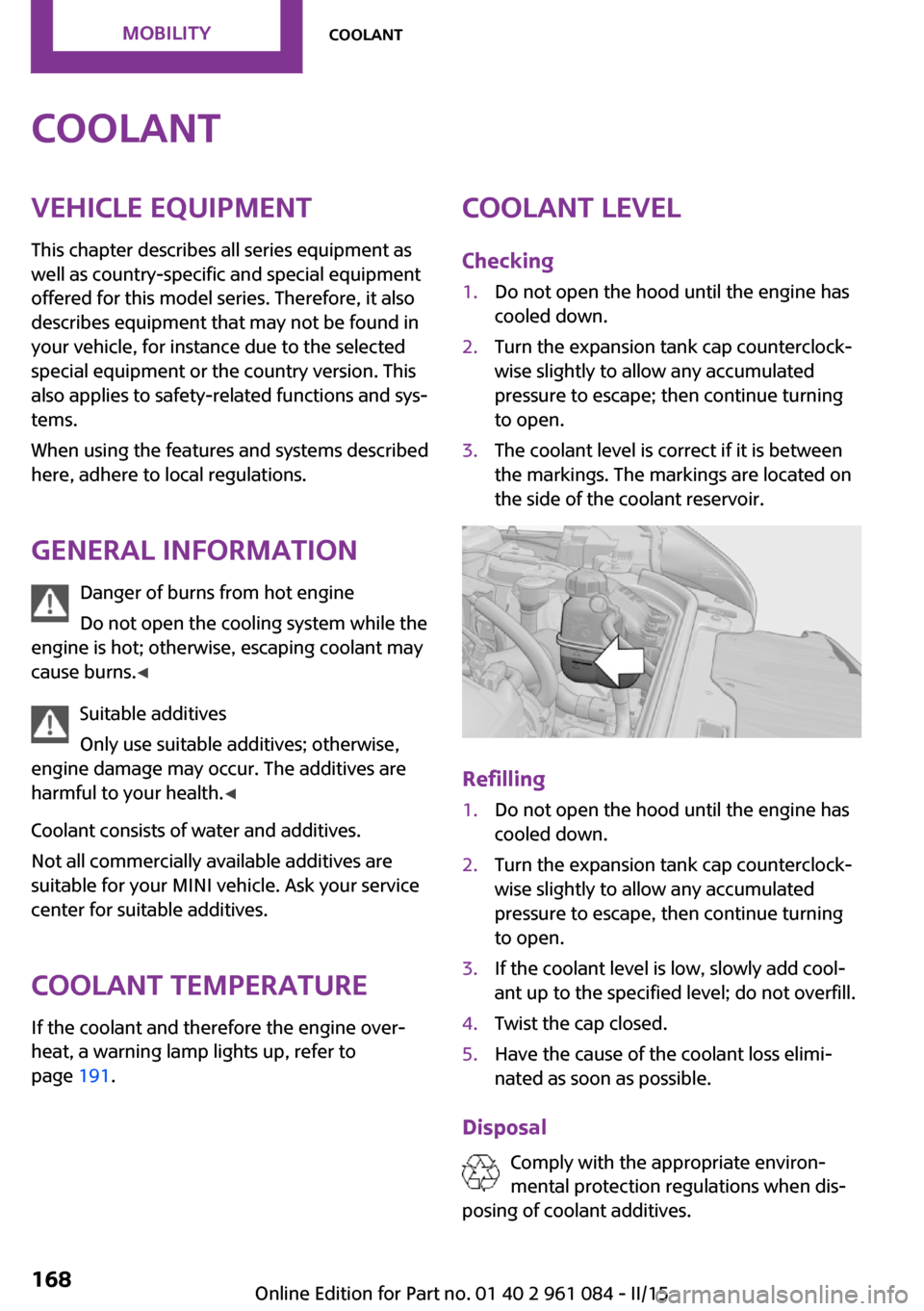
to open.3.The coolant level is correct if it is between
the markings. The markings are located on
the side of the coolant reservoir.
Refilling
1.Do not open the hood until the engine has
cooled down.2.Turn the expansion tank cap counterclock‐
wise slightly to allow any accumulated
pressure to escape, then continue turning
to open.3.If the coolant level is low, slowly add cool‐
ant up to the specified level; do not overfill.4.Twist the cap closed.5.Have the cause of the coolant loss elimi‐
nated as soon as possible.
Disposal
Comply with the appropriate environ‐mental protection regulations when dis‐
posing of coolant additives.
Seite 168MOBILITYCoolant168
Online Edition for Part no. 01 40 2 961 084 - II/15
Page 172 of 223
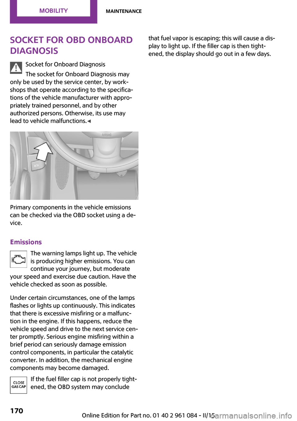
Socket for OBD Onboard
Diagnosis
Socket for Onboard Diagnosis
The socket for Onboard Diagnosis may
only be used by the service center, by work‐
shops that operate according to the specifica‐
tions of the vehicle manufacturer with appro‐
priately trained personnel, and by other
authorized persons. Otherwise, its use may
lead to vehicle malfunctions. ◀
Primary components in the vehicle emissions
can be checked via the OBD socket using a de‐
vice.
Emissions The warning lamps light up. The vehicle
is producing higher emissions. You can
continue your journey, but moderate
your speed and exercise due caution. Have the
vehicle checked as soon as possible.
Under certain circumstances, one of the lamps
flashes or lights up continuously. This indicates
that there is excessive misfiring or a malfunc‐
tion in the engine. If this happens, reduce the
vehicle speed and drive to the next service cen‐
ter promptly. Serious engine misfiring within a
brief period can seriously damage emission
control components, in particular the catalytic
converter. In addition, the mechanical engine
components may become damaged.
If the fuel filler cap is not properly tight‐
ened, the OBD system may conclude
that fuel vapor is escaping; this will cause a dis‐
play to light up. If the filler cap is then tight‐
ened, the display should go out in a few days.Seite 170MOBILITYMaintenance170
Online Edition for Part no. 01 40 2 961 084 - II/15
Page 186 of 223
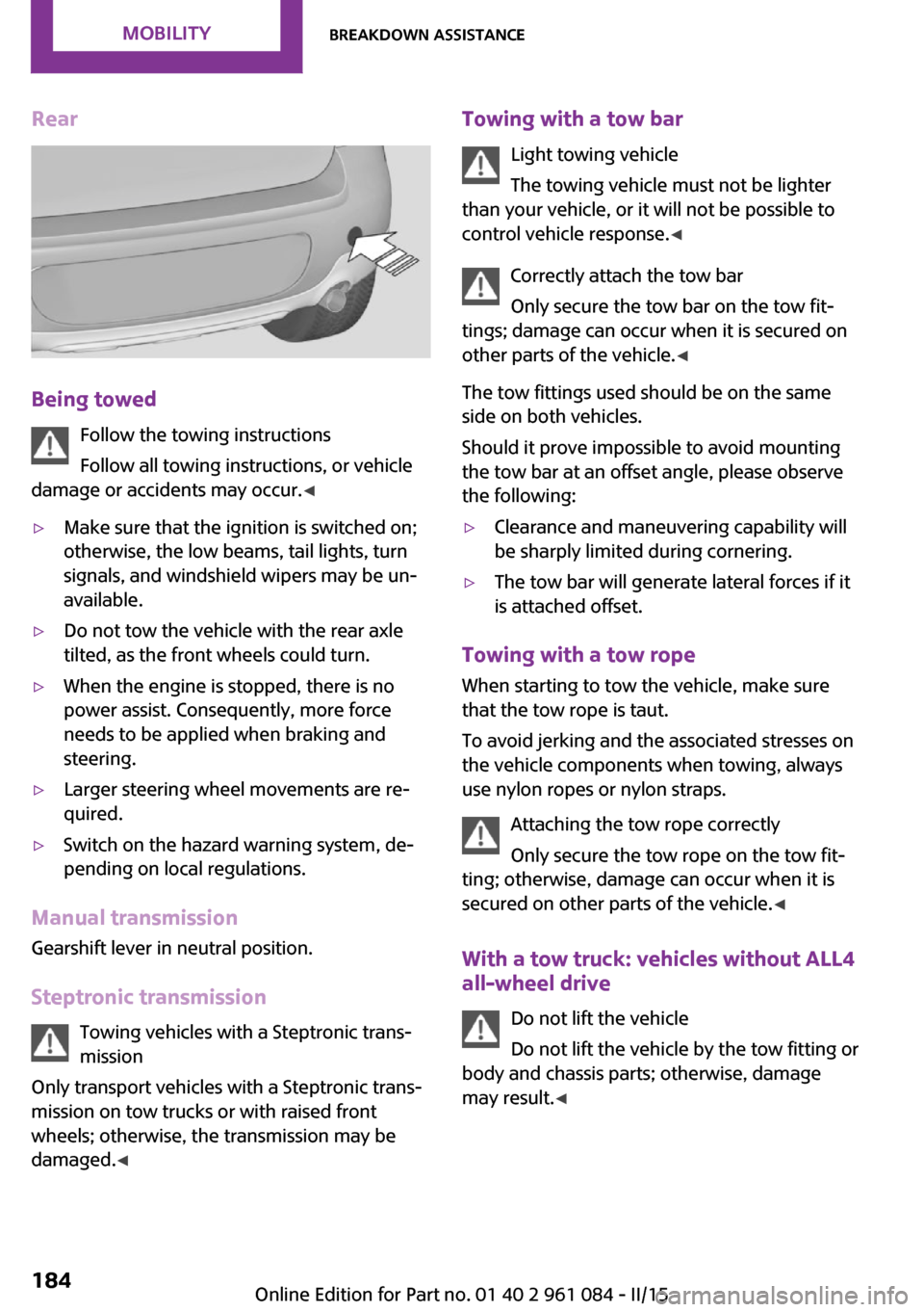
Rear
Being towedFollow the towing instructions
Follow all towing instructions, or vehicle
damage or accidents may occur. ◀
▷Make sure that the ignition is switched on;
otherwise, the low beams, tail lights, turn
signals, and windshield wipers may be un‐
available.▷Do not tow the vehicle with the rear axle
tilted, as the front wheels could turn.▷When the engine is stopped, there is no
power assist. Consequently, more force
needs to be applied when braking and
steering.▷Larger steering wheel movements are re‐
quired.▷Switch on the hazard warning system, de‐
pending on local regulations.
Manual transmission
Gearshift lever in neutral position.
Steptronic transmission Towing vehicles with a Steptronic trans‐
mission
Only transport vehicles with a Steptronic trans‐
mission on tow trucks or with raised front
wheels; otherwise, the transmission may be
damaged. ◀
Towing with a tow bar
Light towing vehicle
The towing vehicle must not be lighter
than your vehicle, or it will not be possible to
control vehicle response. ◀
Correctly attach the tow bar
Only secure the tow bar on the tow fit‐
tings; damage can occur when it is secured on
other parts of the vehicle. ◀
The tow fittings used should be on the same
side on both vehicles.
Should it prove impossible to avoid mounting
the tow bar at an offset angle, please observe
the following:▷Clearance and maneuvering capability will
be sharply limited during cornering.▷The tow bar will generate lateral forces if it
is attached offset.
Towing with a tow rope
When starting to tow the vehicle, make sure
that the tow rope is taut.
To avoid jerking and the associated stresses on
the vehicle components when towing, always
use nylon ropes or nylon straps.
Attaching the tow rope correctly
Only secure the tow rope on the tow fit‐
ting; otherwise, damage can occur when it is
secured on other parts of the vehicle. ◀
With a tow truck: vehicles without ALL4
all-wheel drive
Do not lift the vehicle
Do not lift the vehicle by the tow fitting or
body and chassis parts; otherwise, damage
may result. ◀
Seite 184MOBILITYBreakdown assistance184
Online Edition for Part no. 01 40 2 961 084 - II/15