check engine MINI Paceman 2016 (Mini Connected) User Guide
[x] Cancel search | Manufacturer: MINI, Model Year: 2016, Model line: Paceman, Model: MINI Paceman 2016Pages: 223, PDF Size: 5.52 MB
Page 115 of 223
CAUTION
Objects in unpaved areas, e.g. stones or
branches, can damage the vehicle. There is risk
of property damage. Do not drive on unpaved
terrain. ◀
For your own safety and the safety of passen‐
gers and the vehicle, adhere to the following
points:▷Familiarize yourself with the vehicle before
driving; never take risks.▷Adjust speeds according to road conditions.
The steeper and rougher the road surface
is, the lower the speed should be.▷When driving on steep uphill and downhill
grades: the engine oil and coolant should
be filled nearly to the MAX mark.▷Watch for stones, holes, and other obsta‐
cles and drive around these where possible.▷On bumps and rough roads, avoid contact
between the vehicle body and the ground.
The maximum ground clearance is 6 in‐
ches/15 cm and may vary with the loaded
cargo.▷When driving through water, do not exceed
the maximum water height of 12 in‐
ches/30 cm and drive at walking speed.▷After driving through water, press on the
brake pedal several times at low speeds to
dry the brakes.▷Depending on the prevailing terrain, acti‐
vate Dynamic Traction Control DTC briefly,
refer to page 85.▷When the wheels spin, accelerate to enable
the driving stability control systems to dis‐
tribute the drive force to the individual
wheels.
After driving on poor roads
Adhere to the following points to ensure vehi‐
cle safety:
▷Remove excessive accumulations of dirt
and mud from the vehicle body.▷Clear mud, snow, ice, etc., from the wheels
and tires and check for damage.Seite 115Things to remember when drivingDRIVING TIPS115
Online Edition for Part no. 01 40 2 964 433 - VI/15
Page 120 of 223

Saving fuelVehicle features and op‐tions
This chapter describes all standard, country-
specific and optional features offered with the
series. It also describes features that are not necessarily available in your car, e. g., due to
the selected options or country versions. This
also applies to safety-related functions and sys‐
tems.
When using the features and systems described
here, adhere to local regulations.
General information
Your vehicle contains advanced technology for
the reduction of fuel consumption and emis‐
sions.
Fuel consumption depends on a number of dif‐
ferent factors. The implementation of certain
measures, driving style and regular mainte‐
nance can have an influence on fuel consump‐
tion and on the environmental impact.
Remove unnecessary
cargo
Additional weight increases fuel consumption.
Remove attached partsfollowing use
Remove unneeded auxiliary mirrors, roof or
rear luggage racks after use.
Attached parts on the vehicle impair the aero‐
dynamics and increase the fuel consumption.Close both windows
Open windows causes higher air resistance and
thus increases fuel consumption.
Check the tire inflation
pressure regularly
Check and, if necessary, correct the tire infla‐
tion pressure, refer to page 154, at least twice
a month and before starting on a long trip.
Low tire inflation pressure increases rolling re‐
sistance and thus raises fuel consumption and
tire wear.
Drive away without de‐lay
Do not wait for the engine to warm-up while
the vehicle remains stationary. Start driving right away, but at moderate engine speeds.
This is the fastest way for the cold engine to
reach its operating temperature.
Look well ahead when
driving
Avoid unnecessary acceleration and braking. To
achieve this, maintain a suitable distance to the
vehicle driving ahead of you.
Driving smoothly and looking ahead reduces
fuel consumption.
Avoid high engine speeds
Use 1st gear to get the vehicle in motion. Be‐
ginning with 2nd gear, accelerate rapidly. WhenSeite 120DRIVING TIPSSaving fuel120
Online Edition for Part no. 01 40 2 964 433 - VI/15
Page 164 of 223
Switch on the compressor and let it run for
approx. 3 to 8 minutes to fill sealant into
the tire and achieve a tire inflation pressure
of approx. 1.8 bar/26 psi.
While sealant is being filled, the inflation
pressure may intermittently rise to approx.
5 bar/73 psi. Do not switch off the com‐
pressor in this phase.8.Switch off the compressor.
CAUTION
The compressor can overheat during ex‐
tended operation. There is risk of property
damage. Do not run the compressor for more
than 10 min. ◀
If an air pressure of 1.8 bar/26 psi is not
reached:
1.Unscrew the filling hose 2 from the wheel
and drive forward and back approx.
33 ft/10 m to evenly distribute the sealant
in the tire.2.Inflate the tire again using the compressor.
If the inflation pressure of 1.8 bar/26 psi is still
not reached, the tire is too heavily damaged.
Contact a dealer’s service center or another
qualified service center or repair shop.
Stowing the Mobility System
1.Unscrew the filling hose 2 of the sealant
bottle from the wheel.2.Unscrew the compressor connection hose 6
from the sealant bottle.3.Connect the filling hose 2 of the sealant
bottle with the free connector on the seal‐
ant bottle.
This prevents left-over sealant from escap‐
ing from the bottle.4.Wrap the empty sealant bottle in suitable
material to avoid dirtying the cargo area.5.Stow the Mobility System back in the vehi‐
cle.Distributing the sealant
Drive approx. 3.1 miles/5 km to evenly distrib‐
ute the sealant.
Do not exceed a speed of 50 mph/80 km/h. If
possible, do not drop below a speed of
10 mph/20 km/h.
Correcting the tire inflation pressure1.After driving approx. 3.1 miles/5 km, or
about 10 minutes, stop in a suitable loca‐
tion.2.Screw the connection hose 6 of the com‐
pressor directly onto the tire valve.3.Insert the connector 5 into the power
socket in the passenger compartment.4.Correct the tire inflation pressure to
1.8 bar/26 psi. When the engine is running:▷To increase the inflation pressure:
switch on the compressor. To check the
currently set inflation pressure, switch
off the compressor.▷To reduce the inflation pressure: press
the release button 9.
CAUTION
The compressor can overheat during ex‐
tended operation. There is risk of property
damage. Do not run the compressor for more
than 10 min. ◀
If the inflation pressure is not maintained, take
the vehicle on another drive, distributing the
sealant, refer to page 164. Then repeat steps
1 to 4 once.
If the inflation pressure of 1.8 bar/26 psi is still
not reached, the tire is too heavily damaged.
Contact a dealer’s service center or another
qualified service center or repair shop.
Continuing the trip Do not exceed the maximum permissible speed
of 50 mph/80 km/h.
Replace the not working tire as soon as possi‐
ble and have the wheel balanced.
Seite 164MOBILITYWheels and tires164
Online Edition for Part no. 01 40 2 964 433 - VI/15
Page 168 of 223
Engine oilEngine oil
Vehicle features and options This chapter describes all standard, country-
specific and optional features offered with the series. It also describes features that are notnecessarily available in your car, e. g., due to
the selected options or country versions. This
also applies to safety-related functions and sys‐
tems.
When using the features and systems described
here, adhere to local regulations.
General information
Engine oil consumption depends on the driving
style and the conditions of use. A highly sporty
driving style, for example, results in considera‐
bly higher engine oil consumption.
Therefore, regularly check the engine oil level
after refueling.
Checking the oil level with a dip stick1.Park the vehicle on level ground when the
engine is at operating temperature, i.e., af‐
ter driving continuously for at least
6 2 miles/10 km.2.Switch the engine off.3.After approx. 5 minutes, pull out the dip
stick and wipe it off with a lint-free cloth,
paper towel, etc.4.Carefully insert the dip stick all the way into
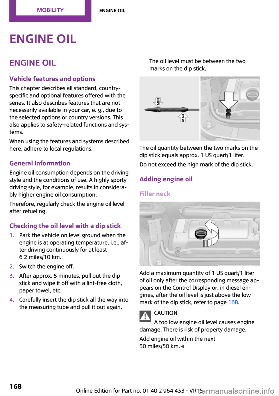
the measuring tube and pull it out again.The oil level must be between the two
marks on the dip stick.
The oil quantity between the two marks on the
dip stick equals approx. 1 US quart/1 liter.
Do not exceed the high mark of the dip stick.
Adding engine oil
Filler neck
Add a maximum quantity of 1 US quart/1 liter
of oil only after the corresponding message ap‐
pears on the Control Display or, in diesel en‐
gines, after the oil level is just above the low
mark of the dip stick, refer to page 168.
CAUTION
A too low engine oil level causes engine
damage. There is risk of property damage.
Add engine oil within the next
30 miles/50 km. ◀
Seite 168MOBILITYEngine oil168
Online Edition for Part no. 01 40 2 964 433 - VI/15
Page 170 of 223
CoolantVehicle features and op‐
tions
This chapter describes all standard, country-
specific and optional features offered with the
series. It also describes features that are not
necessarily available in your car, e. g., due to
the selected options or country versions. This
also applies to safety-related functions and sys‐
tems.
When using the features and systems described
here, adhere to local regulations.
General information WARNING
With the engine hot and the cooling sys‐
tem open, coolant can escape and lead to
burns. There is risk of injuries. Only open the
cooling system with the engine cooled down. ◀
WARNING
Additives are harmful and incorrect addi‐
tives can damage the engine. There is risk of in‐
juries and risk of property damage. Avoid the
contact of articles of clothing, skin or eyes with
additives. Do not swallow any additives. Use
suitable additives only. ◀
Coolant consists of water and additives. Not all commercially available additives are
suitable for the vehicle. Information regarding
suitable additives is available from a dealer’s
service center or another qualified service cen‐
ter or repair shop.Coolant temperature
If the coolant and therefore the engine over‐
heat, a warning lamp lights up, refer to
page 194.
Coolant level Checking1.Do not open the hood until the engine has
cooled down.2.Turn the expansion tank cap counterclock‐
wise slightly to allow any accumulated
pressure to escape; then continue turning
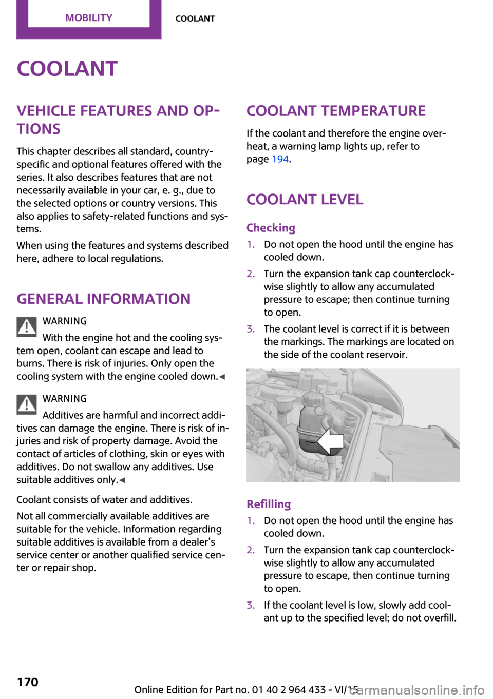
to open.3.The coolant level is correct if it is between
the markings. The markings are located on
the side of the coolant reservoir.
Refilling
1.Do not open the hood until the engine has
cooled down.2.Turn the expansion tank cap counterclock‐
wise slightly to allow any accumulated
pressure to escape, then continue turning
to open.3.If the coolant level is low, slowly add cool‐
ant up to the specified level; do not overfill.Seite 170MOBILITYCoolant170
Online Edition for Part no. 01 40 2 964 433 - VI/15
Page 172 of 223
MaintenanceVehicle features and op‐
tions
This chapter describes all standard, country-
specific and optional features offered with the
series. It also describes features that are not
necessarily available in your car, e. g., due to
the selected options or country versions. This
also applies to safety-related functions and sys‐
tems.
When using the features and systems described
here, adhere to local regulations.
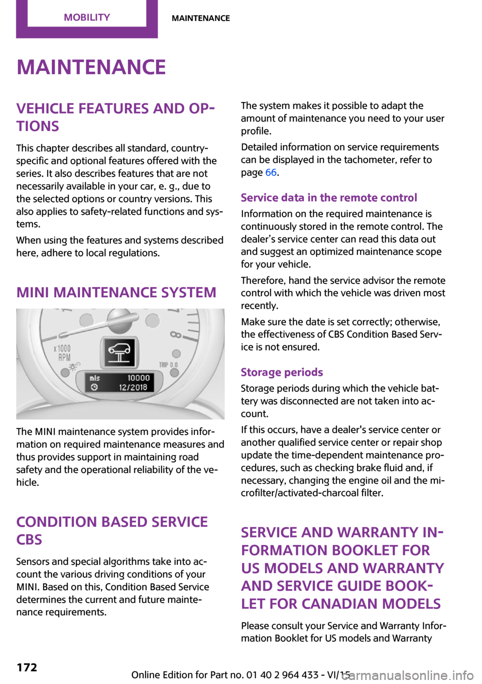
MINI maintenance system
The MINI maintenance system provides infor‐
mation on required maintenance measures and
thus provides support in maintaining road
safety and the operational reliability of the ve‐
hicle.
Condition Based Service
CBS
Sensors and special algorithms take into ac‐
count the various driving conditions of your
MINI. Based on this, Condition Based Service
determines the current and future mainte‐
nance requirements.
The system makes it possible to adapt the
amount of maintenance you need to your user
profile.
Detailed information on service requirements
can be displayed in the tachometer, refer to
page 66.
Service data in the remote control Information on the required maintenance is
continuously stored in the remote control. The
dealer’s service center can read this data out
and suggest an optimized maintenance scope
for your vehicle.
Therefore, hand the service advisor the remote
control with which the vehicle was driven most
recently.
Make sure the date is set correctly; otherwise,
the effectiveness of CBS Condition Based Serv‐
ice is not ensured.
Storage periods
Storage periods during which the vehicle bat‐
tery was disconnected are not taken into ac‐
count.
If this occurs, have a dealer's service center or
another qualified service center or repair shop
update the time-dependent maintenance pro‐
cedures, such as checking brake fluid and, if
necessary, changing the engine oil and the mi‐ crofilter/activated-charcoal filter.
Service and Warranty In‐formation Booklet for
US models and Warranty
and Service Guide Book‐
let for Canadian models
Please consult your Service and Warranty Infor‐
mation Booklet for US models and WarrantySeite 172MOBILITYMaintenance172
Online Edition for Part no. 01 40 2 964 433 - VI/15
Page 173 of 223

and Service Guide Booklet for Canadian models
for additional information on service require‐
ments.
The manufacturer of your vehicle recommends
that maintenance and repair be performed by a
dealer’s service center or another qualified
service center or repair shop. Records of regu‐
lar maintenance and repair work should be re‐
tained.
Socket for OBD Onboard
Diagnosis
CAUTION
The socket for Onboard Diagnosis is an
intricate component intended to be used in
conjunction with specialized equipment to
check the vehicle’s primary emissions system.
Improper use of the socket for Onboard Diag‐
nosis, or contact with the socket for Onboard
Diagnosis for other than its intended purpose,
can cause vehicle malfunctions and creates
risks of personal and property damage. Given
the foregoing, the manufacture of your vehicle
strongly recommends that access to the socket
for Onboard Diagnosis be limited to a dealer's
service center or another qualified service cen‐
ter or repair shop or other persons that have
the specialized training and equipment for pur‐
poses of properly utilizing the socket for On‐
board Diagnosis. ◀
Primary components in the vehicle emissions
can be checked via the OBD socket using a de‐
vice.
Emissions
The warning lamps light up. The vehicle
is producing higher emissions. Further
driving at a moderate pace is possible.
Have the vehicle checked as soon as possible.
Under certain circumstances, one of the lamps
flashes or lights up continuously. This indicates
that there is excessive misfiring or a malfunc‐
tion in the engine. In this situation, decrease
the vehicle speed and immediately drive to a
dealer’s service center or another qualified
service center or repair shop. Serious engine
misfiring within a brief period can seriously
damage emission control components, in par‐
ticular the catalytic converter. In addition, the
mechanical engine components may become
damaged.
If the fuel filler cap is not properly tight‐
ened, the OBD system may conclude
that fuel vapor is escaping; this will
cause a display to light up. If the filler cap is
then tightened, the display should go out in a
few days.Seite 173MaintenanceMOBILITY173
Online Edition for Part no. 01 40 2 964 433 - VI/15
Page 182 of 223
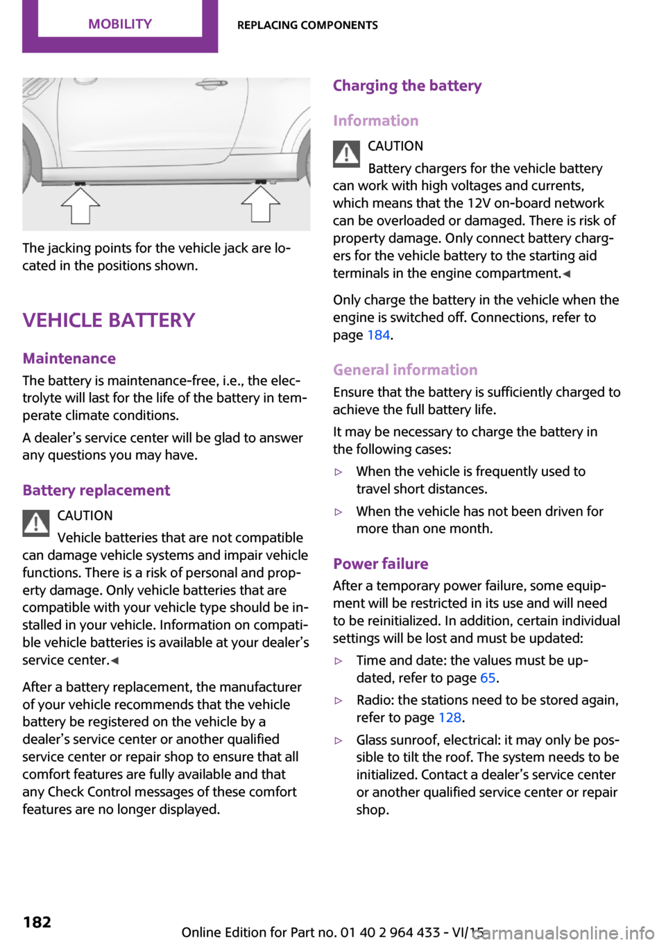
The jacking points for the vehicle jack are lo‐
cated in the positions shown.
Vehicle battery Maintenance
The battery is maintenance-free, i.e., the elec‐
trolyte will last for the life of the battery in tem‐
perate climate conditions.
A dealer’s service center will be glad to answer
any questions you may have.
Battery replacement CAUTION
Vehicle batteries that are not compatible
can damage vehicle systems and impair vehicle
functions. There is a risk of personal and prop‐
erty damage. Only vehicle batteries that are
compatible with your vehicle type should be in‐
stalled in your vehicle. Information on compati‐
ble vehicle batteries is available at your dealer’s
service center. ◀
After a battery replacement, the manufacturer
of your vehicle recommends that the vehicle
battery be registered on the vehicle by a
dealer’s service center or another qualified
service center or repair shop to ensure that all
comfort features are fully available and that
any Check Control messages of these comfort
features are no longer displayed.
Charging the battery
Information CAUTION
Battery chargers for the vehicle battery
can work with high voltages and currents, which means that the 12V on-board network
can be overloaded or damaged. There is risk of
property damage. Only connect battery charg‐
ers for the vehicle battery to the starting aid
terminals in the engine compartment. ◀
Only charge the battery in the vehicle when the
engine is switched off. Connections, refer to
page 184.
General information
Ensure that the battery is sufficiently charged to
achieve the full battery life.
It may be necessary to charge the battery in
the following cases:▷When the vehicle is frequently used to
travel short distances.▷When the vehicle has not been driven for
more than one month.
Power failure
After a temporary power failure, some equip‐
ment will be restricted in its use and will need
to be reinitialized. In addition, certain individual
settings will be lost and must be updated:
▷Time and date: the values must be up‐
dated, refer to page 65.▷Radio: the stations need to be stored again,
refer to page 128.▷Glass sunroof, electrical: it may only be pos‐
sible to tilt the roof. The system needs to be
initialized. Contact a dealer’s service center
or another qualified service center or repair
shop.Seite 182MOBILITYReplacing components182
Online Edition for Part no. 01 40 2 964 433 - VI/15
Page 184 of 223

Breakdown assistanceVehicle features and op‐
tions
This chapter describes all standard, country-
specific and optional features offered with the
series. It also describes features that are not
necessarily available in your car, e. g., due to
the selected options or country versions. This
also applies to safety-related functions and sys‐
tems.
When using the features and systems described
here, adhere to local regulations.
Hazard warning flash‐
ers
The button is located on the speedometer.
Warning triangle
Under the loading edge in the cargo area.
To remove, open the two fasteners.
First aid kit Some of the articles contained in the first aid kit
have a limited service life. Therefore, check the
use-by dates of the contents regularly and re‐
place the items before they expire.
The first aid kit is located in the left side trim on
the cargo area floor or under the loading floor.
Roadside Assistance Service availability
Roadside Assistance can be reached around the
clock in many countries. You can obtain assis‐
tance there in the event of a vehicle break‐
down.
Roadside Assistance A phone number for Roadside Assistance can
be displayed, refer to page 144, via the radio.
Jump-starting InformationIf the battery is discharged, the engine can be
started using the battery of another vehicle and
Seite 184MOBILITYBreakdown assistance184
Online Edition for Part no. 01 40 2 964 433 - VI/15
Page 185 of 223
two jumper cables. In the same way, you can
help jump-start another vehicle. Only use
jumper cables with fully insulated clamp han‐
dles.
To prevent personal injury or damage to both
vehicles, adhere strictly to the following proce‐
dure.
DANGER
Contact with live components can lead to
an electric shock. There is risk of injuries or
danger to life. Do not touch any components
that are under voltage. ◀
Preparation1.Check whether the battery of the other ve‐
hicle has a voltage of 12 volts and approxi‐
mately the same capacitance in Ah. This in‐
formation can be found on the battery.2.Switch off the engine of the assisting vehi‐
cle.3.Switch off any electronic systems/power
consumers in both vehicles.
CAUTION
In the case of body contact between the
two vehicles, a short circuit can occur during
jump-starting. There is risk of property damage.
Make sure that no body contact occurs. ◀
Connecting jumper cables
WARNING
If the jumper cables are connected in the
incorrect order, sparks formation can occur.
There is risk of injuries. Pay attention to the cor‐
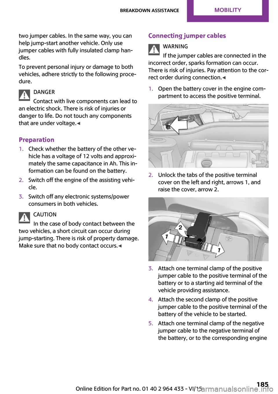
rect order during connection. ◀1.Open the battery cover in the engine com‐
partment to access the positive terminal.2.Unlock the tabs of the positive terminal
cover on the left and right, arrows 1, and
raise the cover, arrow 2.3.Attach one terminal clamp of the positive
jumper cable to the positive terminal of the
battery or to a starting aid terminal of the
vehicle providing assistance.4.Attach the second clamp of the positive
jumper cable to the positive terminal of the
battery of the vehicle to be started.5.Attach one terminal clamp of the negative
jumper cable to the negative terminal of
the battery, or to the corresponding engineSeite 185Breakdown assistanceMOBILITY185
Online Edition for Part no. 01 40 2 964 433 - VI/15