steering MINI Paceman 2016 (Mini Connected) User Guide
[x] Cancel search | Manufacturer: MINI, Model Year: 2016, Model line: Paceman, Model: MINI Paceman 2016Pages: 223, PDF Size: 5.52 MB
Page 81 of 223
of an accident. Do not continue driving if the
vehicle is not equipped with run-flat tires. Fol‐
low the information on run-flat tires and con‐
tinued driving with these tires. ◀
When a low inflation pressure is indicated, DSC
Dynamic Stability Control is switched on if nec‐
essary.
Actions in the event of a flat tire Normal tires1.Identify the damaged tire.
Do this by checking the air pressure in all
four tires. The tire pressure gauge of the
Mobility System, refer to page 162, can be
used for this purpose.
If the tire inflation pressure in all four tires is
correct, the Tire Pressure Monitor may not
have been reset. Reset the system.
If identification of flat tire damage is not
possible, please contact a dealer’s service
center or another qualified service center or
repair shop.2.Rectify the flat tire using the Mobility Sys‐
tem, refer to page 162.
Use of tire sealant, e.g., the Mobility Sys‐
tem, may damage the TPM wheel electron‐
ics. In this case, have the electronics
checked at the next opportunity and have
them replaced if necessary.
Run-flat tires
You can continue driving with a damaged tire
at speeds up to 50 mph/80 km/h.
WARNING
A damaged regular tire with low or miss‐
ing tire inflation pressure impacts handling,
such as steering and braking response. Run-flat
tires can maintain limited stability. There is risk
of an accident. Do not continue driving if the
vehicle is not equipped with run-flat tires. Fol‐
low the information on run-flat tires and con‐
tinued driving with these tires. ◀
Continued driving with a flat tire
If continuing to drive with a damaged tire:1.Avoid sudden braking and steering maneu‐
vers.2.Do not exceed a speed of 50 mph/80 km/h.3.Check the air pressure in all four tires at the
next opportunity.
If the tire inflation pressure in all four tires is
correct, the Tire Pressure Monitor may not
have been reset. Reset the system.
Possible driving distance with complete loss of
tire inflation pressure:
The possible driving distance after a loss of tire
inflation pressure depends on the cargo load
and the driving style and conditions.
For a vehicle containing an average load, the
possible driving distance is ap‐
prox. 50 miles/80 km.
When the vehicle is driven with a damaged tire,
its handling characteristics change, e.g., re‐
duced lane stability during braking, a longer
braking distance, and altered self-steering
properties. Adjust your driving style accord‐
ingly. Avoid abrupt steering maneuvers or driv‐
ing over obstacles, e. g., curbs, potholes, etc.
Because the possible driving distance depends
on how the vehicle is used during the trip, the
actual distance may be smaller or greater de‐
pending on the driving speed, road conditions,
external temperature, cargo load, etc.
WARNING
Your vehicle handles differently when a
run-flat tire is damaged and has low or missing
tire inflation pressure, e.g., your lane stability is
reduced when braking, braking distances are
longer and the self-steering properties will
change. There is risk of an accident.
Drive moderately and do not exceed a speed of
50 mph/80 km/h. ◀
Seite 81SafetyCONTROLS81
Online Edition for Part no. 01 40 2 964 433 - VI/15
Page 84 of 223
Driving stability control systemsVehicle features and op‐
tions
This chapter describes all standard, country-
specific and optional features offered with the
series. It also describes features that are not
necessarily available in your car, e. g., due to
the selected options or country versions. This
also applies to safety-related functions and sys‐
tems.
When using the features and systems described
here, adhere to local regulations.
Antilock Brake System
ABS
ABS prevents locking of the wheels during braking.
Steerability is maintained even during full brak‐ ing. This increases active driving safety.
ABS is operational every time you start the en‐
gine.
Electronic brake-force distribution EBVThe system controls the brake pressure in the
rear wheels to ensure stable braking behavior.
CBC Cornering Brake Control When braking in curves or during a lane
change, driving stability and steering response
are improved further.
Brake assistant
When the brakes are applied rapidly, this sys‐
tem automatically produces the maximum
braking force boost. In this way, the system
helps keep the braking distance as short aspossible. This system utilizes all of the benefits
provided by ABS.
Do not reduce the pressure on the brake pedal
for the duration of full braking.
Dynamic Stability Con‐
trol DSC
The concept
DSC prevents traction loss in the driving wheels
when driving away and accelerating.
DSC also recognizes unstable vehicle condi‐
tions, such as fishtailing or nose-diving. Subject
to physical limits, DSC helps to keep the vehicle
on a steady course by reducing engine speed
and by applying brakes to the individual
wheels.
Adapt your driving style to the situation, for an
appropriate driving style is always the responsi‐
bility of the driver.
DSC is operational every time you start the en‐
gine.
WARNING
When driving with roof load, e.g. with
roof-mounted luggage rack, driving safety may
not be ensured in driving-critical situations due
to the elevated center of gravity. There is risk of
accidents or risk of property damage. Do not
deactivate Dynamic Stability Control DSC when
driving with roof load. ◀Seite 84CONTROLSDriving stability control systems84
Online Edition for Part no. 01 40 2 964 433 - VI/15
Page 86 of 223
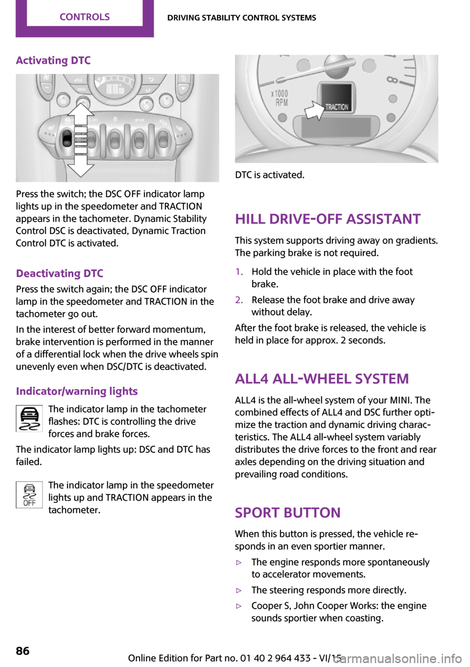
Activating DTC
Press the switch; the DSC OFF indicator lamp
lights up in the speedometer and TRACTION
appears in the tachometer. Dynamic Stability
Control DSC is deactivated, Dynamic Traction
Control DTC is activated.
Deactivating DTC Press the switch again; the DSC OFF indicator
lamp in the speedometer and TRACTION in the
tachometer go out.
In the interest of better forward momentum,
brake intervention is performed in the manner
of a differential lock when the drive wheels spin
unevenly even when DSC/DTC is deactivated.
Indicator/warning lights The indicator lamp in the tachometer
flashes: DTC is controlling the drive
forces and brake forces.
The indicator lamp lights up: DSC and DTC has
failed.
The indicator lamp in the speedometer
lights up and TRACTION appears in the
tachometer.
DTC is activated.
Hill drive-off assistant This system supports driving away on gradients.
The parking brake is not required.
1.Hold the vehicle in place with the foot
brake.2.Release the foot brake and drive away
without delay.
After the foot brake is released, the vehicle is
held in place for approx. 2 seconds.
ALL4 all-wheel system ALL4 is the all-wheel system of your MINI. The
combined effects of ALL4 and DSC further opti‐
mize the traction and dynamic driving charac‐
teristics. The ALL4 all-wheel system variably
distributes the drive forces to the front and rear
axles depending on the driving situation and
prevailing road conditions.
Sport button When this button is pressed, the vehicle re‐
sponds in an even sportier manner.
▷The engine responds more spontaneously
to accelerator movements.▷The steering responds more directly.▷Cooper S, John Cooper Works: the engine
sounds sportier when coasting.Seite 86CONTROLSDriving stability control systems86
Online Edition for Part no. 01 40 2 964 433 - VI/15
Page 88 of 223

Driving comfortVehicle features and op‐
tions
This chapter describes all standard, country-
specific and optional features offered with the
series. It also describes features that are not
necessarily available in your car, e. g., due to
the selected options or country versions. This
also applies to safety-related functions and sys‐
tems.
When using the features and systems described
here, adhere to local regulations.
Cruise control
The concept
The system is functional at speeds beginning at
approx. 20 mph/30 km/h.
The vehicle stores and maintains the speed
specified using the controls on the steering
wheel.
WARNING
The use of the system can lead to an in‐
creased risk of accidents in the following situa‐
tions:▷On winding roads.▷In heavy traffic.▷On slippery roads, in fog, snow or rain, or
on a loose road surface.
There is risk of accidents or risk of property
damage. Only use the system if driving at con‐
stant speed is possible. ◀
Controls
Overview1Maintaining, storing, and increasing the
speed2Activating/deactivating cruise control3Maintaining, storing, and reducing the
speed4Resuming cruise control
Switching on
Press button 2.
The indicator lamp lights up in thespeedometer. Cruise control is ready to
operate and can be activated.
Switch off WARNING
The system does not relieve from the per‐
sonal responsibility to correctly assess the traf‐
fic situation. Based on the limits of the system,
it cannot independently react to all traffic situa‐
tions. There is risk of an accident. Adjust the
driving style to the traffic conditions. Watch
traffic closely and actively interfere in the re‐
spective situations. ◀
Press button 2.
▷When activated: press twice.▷When interrupted: press once.Seite 88CONTROLSDriving comfort88
Online Edition for Part no. 01 40 2 964 433 - VI/15
Page 99 of 223
pending on how long the adjustment button is
pressed:▷Press briefly: switch the display on/off.▷3 to 6 seconds: set the compass zone.▷6 to 9 seconds: calibrate the compass.▷9 to 12 seconds: set left-hand/right hand
steering.▷12 to 15 seconds: set the language.
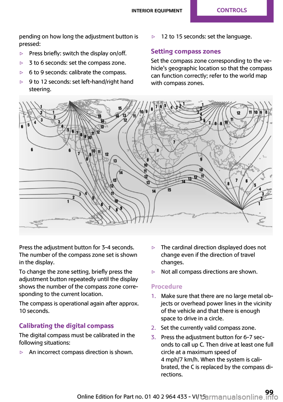
Setting compass zones
Set the compass zone corresponding to the ve‐
hicle's geographic location so that the compass
can function correctly; refer to the world map
with compass zones.
Press the adjustment button for 3‑4 seconds.
The number of the compass zone set is shown
in the display.
To change the zone setting, briefly press the
adjustment button repeatedly until the display
shows the number of the compass zone corre‐
sponding to the current location.
The compass is operational again after approx.
10 seconds.
Calibrating the digital compass The digital compass must be calibrated in the
following situations:▷An incorrect compass direction is shown.▷The cardinal direction displayed does not
change even if the direction of travel
changes.▷Not all compass directions are shown.
Procedure
1.Make sure that there are no large metal ob‐
jects or overhead power lines in the vicinity
of the vehicle and that there is enough
space to drive in a circle.2.Set the currently valid compass zone.3.Press the adjustment button for 6‑7 sec‐
onds to call up C. Then drive at least one full
circle at a maximum speed of
4 mph/7 km/h. When the system is cali‐
brated, the C is replaced by the compass di‐
rections.Seite 99Interior equipmentCONTROLS99
Online Edition for Part no. 01 40 2 964 433 - VI/15
Page 100 of 223

Right-hand/left-hand steering
The digital compass is set for right-hand or left-
hand steering at the factory.
Setting the language
Press the adjustment button for 12‑13 seconds.
Briefly press the adjustment button again to
switch between English "E" and German "O".
The setting is automatically saved after approx.
10 seconds.
Cupholders and ashtray/
lighter
Cupholders
Two cupholders are located in the center con‐
sole in the front.
MINI Countryman: two additional cupholders
are located at the end of the center console in
the rear. Additional cupholders can be installed
on the center rail.
MINI Paceman: additional cupholders are lo‐
cated in the console between the rear seats.
Depending on the equipment, additional cu‐
pholders can be installed on the center rail.
WARNING
Unsuitable containers in the cup holder
and hot beverages can damage the cup holder
and increase the risk of injuries in the event of
an accident. There is risk of injuries or risk of
property damage. Use light-weight, unbreaka‐
ble, and sealable containers. Do not transport
hot beverages. Do not force objects into the
cup holder. ◀
Ashtray
The ashtray is located in one of the cupholders
in the center console at the front.
EmptyingTake out the entire ashtray, arrow.
When installing, ensure that the ashtray is in‐
serted in the cupholder with the adapter.
Lighter
With the engine running or the ignition
switched on, press in the cigarette lighter.
Seite 100CONTROLSInterior equipment100
Online Edition for Part no. 01 40 2 964 433 - VI/15
Page 113 of 223
Closing the tailgateWARNING
An open tailgate protrudes from the vehi‐
cle and can endanger occupants and other traf‐
fic participants or damage the vehicle in the
event of an accident, braking or evasive ma‐
neuvers. In addition, exhaust fumes may enter
the vehicle interior. There is risk of injuries or
risk of property damage. Do not drive with the
tailgate open. ◀
If, despite this, the vehicle must be driven with
the tailgate open:▷Drive moderately.▷Close all windows and the glass sunroof.▷Switch off recirculated air mode and greatly
increase the blower speed.
Hot exhaust system
WARNING
During driving operation, high tempera‐
tures can occur underneath the body, e.g.
caused by the exhaust gas system. If combusti‐
ble materials, such as leaves or grass, come in
contact with hot parts of the exhaust gas sys‐
tem, these materials can ignite. There is risk of
injuries or risk of property damage.
Do not remove the heat shields installed and
never apply undercoating to them. Make sure
that no combustible materials can come in con‐
tact with hot vehicle parts in driving operation,
idle or during parking. Do not touch the hot ex‐
haust system. ◀
Mobile communication devices in the vehicle
WARNING
The vehicle's performance may be af‐
fected by interference from high frequency
radio signals. These signals are emitted by a
series of transmission systems, such as from air
traffic beacons or relay stations for mobile tele‐
communications.
If you have problems of this nature, we recom‐
mend that you consult your dealer’s service
center or another qualified service center or re‐
pair shop. ◀
Hydroplaning On wet or slushy roads, a wedge of water can
form between the tires and road surface.
This phenomenon is referred to as hydroplan‐
ing. It is characterized by a partial or complete
loss of contact between the tires and the road
surface, ultimately undermining your ability to
steer and brake the vehicle.
The risk of hydroplaning increases as the tire
tread depth decreases. Minimum tread depth,
refer to page 160.
Driving through water Drive though calm water only if it is not deeper
than 12 inches/30 cm and at this height, no
faster than walking speed, up to
6 mph/10 km/h.
Using the parking brake on inclines On inclines, do not hold the vehicle stationary
with a slipping clutch for extended period; use
the parking brake instead. Otherwise, the
clutch will be subject to increased wear.
Support from the hill drive-off assistant, refer to
page 86.
Braking safely The vehicle is equipped with ABS as a standardfeature.
Applying the brakes fully is the most effective
way of braking in situations when this is neces‐
sary.
The vehicle maintains steering responsiveness.
You can still avoid any obstacles with a mini‐
mum of steering effort.
Pulsation of the brake pedal and sounds from
the hydraulic circuits indicate that ABS is in its
active mode.Seite 113Things to remember when drivingDRIVING TIPS113
Online Edition for Part no. 01 40 2 964 433 - VI/15
Page 114 of 223

Objects in the area around the pedalsWARNING
Objects in the driver's floor area can limit
the pedal distance or block a depressed pedal.
There is risk of an accident. Stow objects in the
vehicle such that they are secured and cannot
enter into the driver's floor area. Use floor mats
that are suitable for the vehicle and can be
safely attached to the floor. Do not use loose
floor mats and do not layer several floor mats.
Make sure that there is sufficient clearance for
the pedals. Ensure that the floor mats are se‐
curely fastened again after they were removed,
e.g. for cleaning. ◀
Driving in wet conditions When roads are wet or there is heavy rain,
briefly exert gentle pressure on the brake pedal
every few miles.
Ensure that this action does not endanger other
road users.
The heat generated in this process helps dry
the brake discs and pads.
In this way braking efficiency will be available
when you need it.
Hills
Drive long or steep downhill gradients in the
gear in which the least braking is required. Oth‐
erwise, the brake system may overheat, result‐
ing in a reduction in the brake system effi‐
ciency.
You can increase the engine's braking effect by
shifting down, going all the way to first gear, if
necessary.
Downshifting in manual mode of the Steptronic
transmission, refer to page 58.
WARNING
Light but consistent brake pressure can
lead to high temperatures, brakes wearing out
and possibly even brake failure. There is risk ofan accident. Avoid placing excessive load on
the brake system. ◀
WARNING
In idle or with the engine switched off,
safety-relevant functions are restricted or not
available anymore, e.g. braking effect of the
engine or braking force and steering support.
There is risk of an accident. Do not drive in idle
or with the engine switched off. ◀
Brake disc corrosion Corrosion on the brake discs and contamina‐
tion on the brake pads are furthered by:▷Low mileage.▷Extended periods when the vehicle is not
used at all.▷Infrequent use of the brakes.
Corrosion occurs when the minimum pressure
that must be exerted by the pads during brake
applications to clean the discs is not reached.
Should corrosion form on the brake discs, the
brakes will tend to respond with a pulsating ef‐
fect that generally cannot be corrected.
When the vehicle is parked
When using the automatic climate control, con‐
densation water develops that exits under‐
neath the vehicle.
Therefore, traces of condensed water under the
vehicle are normal.
After the engine is switched off, the coolant
pump may continue running for some time in
the MINI Cooper S. This causes noises in the en‐
gine compartment.
Driving on poor roadsYour MINI with ALL4 all-wheel drive feels com‐
fortable on all streets and roads. It combines an
all-wheel drive system with the advantages of a
normal passenger car.
Seite 114DRIVING TIPSThings to remember when driving114
Online Edition for Part no. 01 40 2 964 433 - VI/15
Page 118 of 223

Securing cargoLashing eyes in the cargo area
MINI Countryman
MINI Paceman
Securing cargo
▷Secure smaller and lighter pieces with tight‐
ening belts or straps.▷Secure larger and heavier pieces with cargo
straps.
Adhere to the information included with
the cargo straps.▷Eight mounting eyes are available for fas‐
tening the cargo straps.
Two of them are located on the side wall of
the cargo area, arrows 1, and two are lo‐
cated on the rear wall of the cargo area, ar‐
rows 2.
WARNING
Improperly stowed objects can shift and
be thrown into the car's interior, e.g. in the
event of an accident or during braking and eva‐
sive maneuvers. Vehicle occupants can be hit
and injured. There is risk of injuries. Stow and
secure objects and cargo properly.
Do not secure cargo using the upper LATCH
mounting points, refer to page 48; otherwise,
these may become damaged. ◀
Roof-mounted luggage
rack
InformationA special rack system is available as an optional
accessory.
Securing
Follow the installation instructions of the roof
rack.
Ensure that adequate clearance is available for
the movement of the glass sunroof.
Loading Because roof racks raise the vehicle's center ofgravity when loaded, they have a major effect
on vehicle handling and steering response.
Therefore, note the following when loading and driving:▷Do not exceed the approved roof/axle
loads and the approved gross vehicle
weight.▷Distribute the roof load uniformly.▷The roof load should not extend past the
loading area.▷Always load the heaviest pieces on the bot‐
tom.▷Secure the roof luggage firmly, e.g., tie with
ratchet straps.▷Do not let objects project into the opening
path of the tailgate.▷Drive smoothly. Avoid sudden acceleration
and braking maneuvers. Take corners gen‐
tly.Seite 118DRIVING TIPSLoading118
Online Edition for Part no. 01 40 2 964 433 - VI/15
Page 142 of 223

If all points in this list have been checked and
the required function is still not available, con‐
tact the hotline or a dealer’s service center or
another qualified service center or repair shop.
Controls▷Accept/reject a call.▷Dial a phone number.▷Dial a phone number from the phone book.▷Dial a stored phone number, such as from
the list of accepted calls.▷End the call.
When the ignition and the radio ready state are
switched off, such as after the remote control is
removed, an existing call can be continued for
up to 25 minutes on the hands-free system.
Adjusting the volume
Turn the knob until the desired volume is se‐
lected. Settings are stored for the remote con‐
trol currently in use.
The ringer volume of incoming calls and the call
volume can be adjusted independently.
When a call is placed using the hands-free sys‐
tem, the audio sources are muted.
Switching the microphone to mute
When a call is active, the microphone can be
muted.
"MUTE"
A microphone that has been switched to mute
is automatically reactivated when a new con‐
nection is established.
Incoming call
Receiving calls If the number of the caller is stored in the
phone book and is transmitted by the network,
the name of the contact is displayed. Other‐
wise, only the phone number is displayed.
Accepting a call Briefly press the button on the steering
wheel or radio.
or
"YES"
Rejecting a call
"NO"
Ending a call Briefly press the button on the steering
wheel or radio.
or
"END"
Entering a phone number
Dialing a number1.Switch on the radio ready state or the igni‐
tion.2. Press the button.3."PHONE"4."#"5.Enter the desired phone number on the
buttons 0–9.Seite 142COMMUNICATIONTelephone142
Online Edition for Part no. 01 40 2 964 433 - VI/15