wheel MINI Paceman 2016 (Mini Connected) User Guide
[x] Cancel search | Manufacturer: MINI, Model Year: 2016, Model line: Paceman, Model: MINI Paceman 2016Pages: 223, PDF Size: 5.52 MB
Page 52 of 223

Steptronic transmissionRemote control in the ignition lock or, with
Comfort Access, inside the vehicle, refer to
page 28.1.Depress the brake pedal.2.Move the selector lever to position P or N.3.Press the Start/Stop button.
The ignition is activated automatically for a cer‐
tain time and is stopped as soon as the engine
starts.
Engine stop
General information WARNING
Unattended children or animals can move
the vehicle and endanger themselves and traf‐
fic, e.g. with the following actions:
▷Pressing the Start/Stop button.▷Releasing the parking brake.▷Opening and closing of doors or windows.▷Shifting the selector lever into neutral.▷Using vehicle equipment.
There is risk of accidents or injuries. Do not
leave children or animals unattended in the ve‐
hicle. Carry remote control along when exiting
and lock the vehicle. ◀
WARNING
An unsecured vehicle can put itself into
motion and roll away. There is risk of an acci‐
dent. Before exiting, secure the vehicle against
rolling.
In order to ensure that the vehicle is secured
against rolling away, observe the following:
▷Set the parking brake.▷On uphill grades or on a slope, turn the
front wheels in the direction of the curb.▷On uphill grades or on a slope, additionally
secure the vehicle, e.g. with a wheel
chock. ◀
Before driving into a car wash
To make it possible for the vehicle to roll in an
automatic car wash, follow the information on
Washing in automatic car washes, refer to
page 190.
Switching off the engine
Manual transmission
1.With the vehicle at a standstill, press the
Start/Stop button.2.Shift into first gear or reverse.3.Set the parking brake firmly.4.Remove the remote control from the igni‐
tion lock.
Steptronic transmission
1.Engage transmission position P with the ve‐
hicle stopped.2.Press the Start/Stop button.3.Set the parking brake firmly.4.Remove the remote control from the igni‐
tion lock.
Parking brake
The concept
The parking brake is primarily intended to pre‐
vent the vehicle from rolling while parked; it
brakes the rear wheels.
Also follow the instructions under Switching off
the engine, refer to page 52.
Setting The lever engages automatically.
Seite 52CONTROLSDriving52
Online Edition for Part no. 01 40 2 964 433 - VI/15
Page 58 of 223

Displays in the tachometer
The selector lever position is displayed and the
engaged gear, such as M4, is displayed in
manual mode.
Changing selector lever positions
▷To prevent the vehicle from creeping after
you select a gear, maintain pressure on the
brake pedal until you are ready to start.▷With the ignition switched on or the engine
running, the selector lever can be moved
out of position P.▷When the vehicle is stationary, step on the
brake before shifting out of P or N; other‐
wise, the selector lever is locked: shiftlock.
A lock prevents accidental shifting into selector
lever positions R and P.
To override the lock, press the button on the
front of the selector lever, see arrow.
P Park
Select only when the vehicle is stationary. The
front wheels are blocked.
R is Reverse
Select only when the vehicle is stationary.
N is NeutralFor example, engage this position in a car
wash. The vehicle can roll.
D Drive Position for normal vehicle operation. All for‐
ward gears are selected automatically.
Under normal operating conditions, fuel con‐
sumption is lowest when you are driving in po‐
sition D.
Kickdown
Kickdown is used to achieve maximum driving
performance. Press on the accelerator beyond
the resistance point at the full throttle position.
Sport program and manual mode M/SActivating the Sport program
Move the selector lever from position D toward
the left into the M/S shifting slot.
The Sport program is activated and DS is dis‐
played. This position is recommended for a per‐
formance-oriented driving style.
To deactivate the Sport program or manual
mode M/S, move the selector lever to the right
into position D.
Activating the M/S manual mode Move the selector lever from position D towardthe left into the M/S shifting slot.
Seite 58CONTROLSDriving58
Online Edition for Part no. 01 40 2 964 433 - VI/15
Page 59 of 223

Push the selector lever forward or backward.
Manual mode becomes active and the gear is
changed.
The tachometer displays the engaged gear,
e. g. M1.▷To shift up: press the selector lever back‐
ward.▷To shift down: press the selector lever for‐
ward.
The vehicle only shifts up or down at suitable
engine and road speeds, e.g., it does not shift
down if the engine speed is too high. The se‐
lected gear is briefly displayed in the instru‐
ment panel, followed by the current gear.
Shifting gears using the shift paddleson the steering wheel
The shift paddles on the steering wheel allow
you to shift gears quickly while keeping both hands on the steering wheel.
▷When the shift paddles on the steering
wheel are used to shift gears while in auto‐
matic mode, the transmission switches to
manual mode.▷If the shift paddles are not used to acceler‐
ate or shift gears for a certain amount of
time, the transmission switches back to au‐
tomatic mode.
If the selector lever is in the M/S gear plane,
manual mode remains active.
▷Pull one of the two shift paddles:
The transmission shifts up.▷Press one of the two shift paddles:The transmission shifts down.
The vehicle only shifts up or down at suitable
engine and road speeds, e.g., it does not shift
down if the engine speed is too high. The se‐
lected gear is briefly displayed in the instru‐
ment panel, followed by the current gear.
Manually unlocking the selector leverlock
If the selector lever is locked in position P al‐
though the ignition is switched on, the brake is
depressed, and the button on the selector lever
is pressed, the selector lever lock can be over‐
ridden:
1.Switch off the ignition.2.Unclip the sleeve of the selector lever.3.Pull the sleeve up over the selector lever
until the sleeve is inside out.
Pull off the plug-in cable connector if nec‐
essary.4.Insert the pulling hook 1 into the loop on
the passenger side.
The pulling hook is found in the vehicle
document portfolio or in the pouch of the
wheel change set, refer to page 181.5.Pull the loop upward.6.Move the selector lever into the desired po‐
sition, pressing the button on the front of
the selector lever.Seite 59DrivingCONTROLS59
Online Edition for Part no. 01 40 2 964 433 - VI/15
Page 75 of 223
Knee airbagThe knee airbag supports the legs in a frontal
impact.
Protective action Airbags are not triggered in every impact situa‐
tion, e.g., in less severe accidents or rear-end
collisions.
Information for optimum effect of the
airbags
WARNING
If the seat position is incorrect or the de‐
ployment area of the airbags is impacted, the
airbag system cannot protect as intended or
cause additional injuries due to triggering.
There is risk of injuries or danger to life. Follow
the information on optimum protective effect
of the airbag system. ◀▷Keep at a distance from the airbags.▷Always grasp the steering wheel on the
steering wheel rim, holding your hands at
the 3 o'clock and 9 o'clock positions, to
keep the danger of injury to your hands or
arms as low as possible if the airbag is trig‐
gered.▷There should be no people, animals, or ob‐
jects between an airbag and a person.▷Do not use the cover of the front airbag on
the front passenger side as a storage area.▷Keep the dashboard and window on the
front passenger side clear, i.e., do not cover
with adhesive labels or coverings, and do
not attach holders or cables such as for
navigation instruments and mobile phones.▷Make sure that the front passenger is sitting
correctly, i.e., keeps his or her feet and legs
in the footwell; otherwise, leg injuries can
occur if the front airbag is triggered.▷Do not attach covers, cushions, ball mats or
other items to the front passenger seat un‐less they are specifically determined to be
safe for use on the front passenger seat.▷Do not hang pieces of clothing, such as
jackets, over the backrests.▷Make sure that occupants keep their heads
away from the side airbag and do not rest
against the head airbag; otherwise, injuries
can occur if the airbags are triggered.▷Do not remove the airbag restraint system.▷Do not remove the steering wheel.▷Do not apply adhesive materials to the air‐
bag cover panels, cover them or modify
them in any way.▷Never modify either the individual compo‐
nents or the wiring in the airbag system.
This also applies to steering wheel covers,
the dashboard, the seats, the roof pillars
and the sides of the headliner.
Even when all instructions are followed closely,
injury from contact with the airbags cannot be
ruled out in certain situations.
The ignition and inflation noise may lead to
short-term and, in most cases, temporary hear‐
ing impairment in sensitive individuals.
Warning notices and information about the air‐
bags can also be found on the sun visors.
Automatic deactivation of the front
passenger airbags
The system determines whether the front pas‐
senger seat is occupied by measuring the elec‐
trical resistance of the human body.
The front, side, and knee airbags on the front
passenger side are activated or deactivated ac‐
cordingly by the system.
The indicator lamp above the interior rearview
mirror, refer to page 76, shows the current
status of the front passenger airbags, deacti‐
vated or activated.
Before transporting a child on the front passen‐
ger seat, read the safety and operating instruc‐
tions under Transporting children safely, refer
to page 45.
Seite 75SafetyCONTROLS75
Online Edition for Part no. 01 40 2 964 433 - VI/15
Page 77 of 223
Operational readiness of airbag system
Information WARNING
Individual components can be hot after
triggering of the airbag system. There is risk of
injuries. Do not touch individual components. ◀
WARNING
Improperly executed work can lead to
failure, malfunction or unintentional triggering of the airbag system. In the case of a malfunc‐
tion, the airbag system could not trigger as in‐ tended in the event of an accident despite re‐
spective accident severity. There is risk of
injuries or danger to life. Have the airbag sys‐
tem checked, repaired, dismantled and scrap‐
ped by a dealer’s service center or another
qualified service center or repair shop. ◀
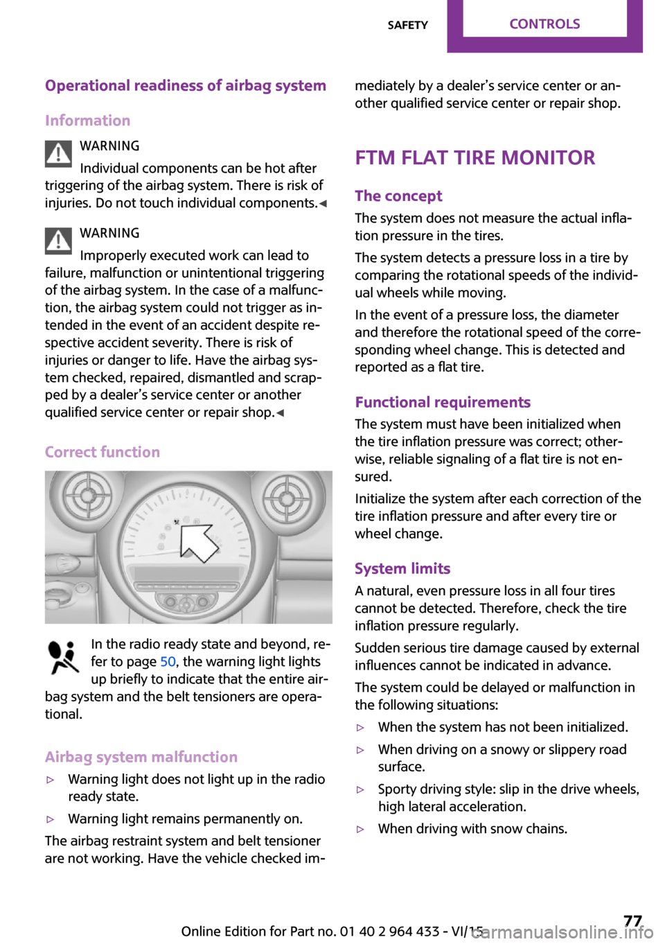
Correct function
In the radio ready state and beyond, re‐
fer to page 50, the warning light lights
up briefly to indicate that the entire air‐
bag system and the belt tensioners are opera‐
tional.
Airbag system malfunction
▷Warning light does not light up in the radio
ready state.▷Warning light remains permanently on.
The airbag restraint system and belt tensioner
are not working. Have the vehicle checked im‐
mediately by a dealer’s service center or an‐
other qualified service center or repair shop.
FTM Flat Tire Monitor
The concept
The system does not measure the actual infla‐
tion pressure in the tires.
The system detects a pressure loss in a tire by
comparing the rotational speeds of the individ‐
ual wheels while moving.
In the event of a pressure loss, the diameter
and therefore the rotational speed of the corre‐
sponding wheel change. This is detected and
reported as a flat tire.
Functional requirements
The system must have been initialized when
the tire inflation pressure was correct; other‐ wise, reliable signaling of a flat tire is not en‐
sured.
Initialize the system after each correction of the
tire inflation pressure and after every tire or
wheel change.
System limits
A natural, even pressure loss in all four tires
cannot be detected. Therefore, check the tire
inflation pressure regularly.
Sudden serious tire damage caused by external
influences cannot be indicated in advance.
The system could be delayed or malfunction in
the following situations:▷When the system has not been initialized.▷When driving on a snowy or slippery road
surface.▷Sporty driving style: slip in the drive wheels,
high lateral acceleration.▷When driving with snow chains.Seite 77SafetyCONTROLS77
Online Edition for Part no. 01 40 2 964 433 - VI/15
Page 79 of 223
center or another qualified service center or
repair shop.2.Rectify the flat tire using the Mobility Sys‐
tem, refer to page 162.
Run-flat tires
You can continue driving with a damaged tire
at speeds up to 50 mph/80 km/h.
Continued driving with a flat tire
If continuing to drive with a damaged tire:
1.Avoid sudden braking and steering maneu‐
vers.2.Do not exceed a speed of 50 mph/80 km/h.3.At the next opportunity, check the inflation
pressure in all four tires.
If the tire inflation pressure in all four tires is
correct, the Flat Tire Monitor may not have
been initialized. In this case, initialize the
system.
Possible driving distance with complete loss of
tire inflation pressure:
The possible driving distance after a loss of tire
inflation pressure depends on the cargo load
and the driving style and conditions.
For a vehicle containing an average load, the
possible driving distance is ap‐
prox. 50 miles/80 km.
When the vehicle is driven with a damaged tire,
its handling characteristics change, e.g., re‐
duced lane stability during braking, a longer
braking distance, and altered self-steering
properties. Adjust your driving style accord‐
ingly. Avoid abrupt steering maneuvers or driv‐
ing over obstacles, e. g., curbs, potholes, etc.
Because the possible driving distance depends
on how the vehicle is used during the trip, the
actual distance may be smaller or greater de‐
pending on the driving speed, road conditions,
external temperature, cargo load, etc.
WARNING
Your vehicle handles differently when a
run-flat tire is damaged and has low or missing
tire inflation pressure, e.g., your lane stability is
reduced when braking, braking distances are
longer and the self-steering properties will
change. There is risk of an accident.
Drive moderately and do not exceed a speed of
50 mph/80 km/h. ◀
Final tire failure
Vibrations or loud noises while driving can indi‐
cate the final failure of a tire. Reduce speed and
stop, otherwise, pieces of the tire could come
loose and cause an accident. Do not continue
driving. Contact a dealer’s service center or an‐
other qualified service center or repair shop.
Tire Pressure Monitor
TPM
The concept
The system monitors the tire pressure in the
four mounted tires. The system notifies you if
there is a significant loss of pressure in one or
more tires. Sensors in the tire valves measure
the tire pressure.
Information
To operate the system, also note the additional
information and instructions contained under
Tire inflation pressure, refer to page 154.
Functional requirements
The system must have been reset while the in‐
flation pressure was correct; otherwise, it may
not reliably signal a loss in pressure.
Perform a system reset after adjusting the tire
inflation pressure to a new value and after
changing a tire or wheel
Always use wheels with TPM electronics to en‐
sure that the system will operate properly.Seite 79SafetyCONTROLS79
Online Edition for Part no. 01 40 2 964 433 - VI/15
Page 80 of 223
Performing a reset
Perform a system reset after adjusting the tire
inflation pressure to a new value and after
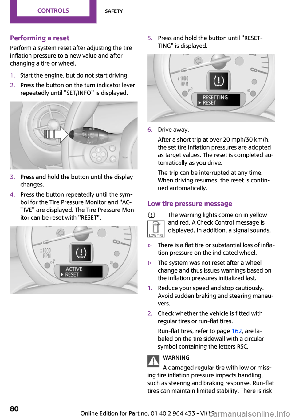
changing a tire or wheel.1.Start the engine, but do not start driving.2.Press the button on the turn indicator lever
repeatedly until "SET/INFO" is displayed.3.Press and hold the button until the display
changes.4.Press the button repeatedly until the sym‐
bol for the Tire Pressure Monitor and "AC‐
TIVE" are displayed. The Tire Pressure Mon‐
itor can be reset with "RESET".5.Press and hold the button until "RESET‐
TING" is displayed.6.Drive away.
After a short trip at over 20 mph/30 km/h,
the set tire inflation pressures are adopted
as target values. The reset is completed au‐
tomatically as you drive.
The trip can be interrupted at any time.
When driving resumes, the reset is contin‐
ued automatically.
Low tire pressure message
The warning lights come on in yellow
and red. A Check Control message is
displayed. In addition, a signal sounds.
▷There is a flat tire or substantial loss of infla‐
tion pressure on the indicated wheel.▷The system was not reset after a wheel
change and thus issues warnings based on
the inflation pressures initialized last.1.Reduce your speed and stop cautiously.
Avoid sudden braking and steering maneu‐
vers.2.Check whether the vehicle is fitted with
regular tires or run-flat tires.
Run-flat tires, refer to page 162, are la‐
beled on the tire sidewall with a circular
symbol containing the letters RSC.
WARNING
A damaged regular tire with low or miss‐
ing tire inflation pressure impacts handling,
such as steering and braking response. Run-flat
tires can maintain limited stability. There is risk
Seite 80CONTROLSSafety80
Online Edition for Part no. 01 40 2 964 433 - VI/15
Page 81 of 223
of an accident. Do not continue driving if the
vehicle is not equipped with run-flat tires. Fol‐
low the information on run-flat tires and con‐
tinued driving with these tires. ◀
When a low inflation pressure is indicated, DSC
Dynamic Stability Control is switched on if nec‐
essary.
Actions in the event of a flat tire Normal tires1.Identify the damaged tire.
Do this by checking the air pressure in all
four tires. The tire pressure gauge of the
Mobility System, refer to page 162, can be
used for this purpose.
If the tire inflation pressure in all four tires is
correct, the Tire Pressure Monitor may not
have been reset. Reset the system.
If identification of flat tire damage is not
possible, please contact a dealer’s service
center or another qualified service center or
repair shop.2.Rectify the flat tire using the Mobility Sys‐
tem, refer to page 162.
Use of tire sealant, e.g., the Mobility Sys‐
tem, may damage the TPM wheel electron‐
ics. In this case, have the electronics
checked at the next opportunity and have
them replaced if necessary.
Run-flat tires
You can continue driving with a damaged tire
at speeds up to 50 mph/80 km/h.
WARNING
A damaged regular tire with low or miss‐
ing tire inflation pressure impacts handling,
such as steering and braking response. Run-flat
tires can maintain limited stability. There is risk
of an accident. Do not continue driving if the
vehicle is not equipped with run-flat tires. Fol‐
low the information on run-flat tires and con‐
tinued driving with these tires. ◀
Continued driving with a flat tire
If continuing to drive with a damaged tire:1.Avoid sudden braking and steering maneu‐
vers.2.Do not exceed a speed of 50 mph/80 km/h.3.Check the air pressure in all four tires at the
next opportunity.
If the tire inflation pressure in all four tires is
correct, the Tire Pressure Monitor may not
have been reset. Reset the system.
Possible driving distance with complete loss of
tire inflation pressure:
The possible driving distance after a loss of tire
inflation pressure depends on the cargo load
and the driving style and conditions.
For a vehicle containing an average load, the
possible driving distance is ap‐
prox. 50 miles/80 km.
When the vehicle is driven with a damaged tire,
its handling characteristics change, e.g., re‐
duced lane stability during braking, a longer
braking distance, and altered self-steering
properties. Adjust your driving style accord‐
ingly. Avoid abrupt steering maneuvers or driv‐
ing over obstacles, e. g., curbs, potholes, etc.
Because the possible driving distance depends
on how the vehicle is used during the trip, the
actual distance may be smaller or greater de‐
pending on the driving speed, road conditions,
external temperature, cargo load, etc.
WARNING
Your vehicle handles differently when a
run-flat tire is damaged and has low or missing
tire inflation pressure, e.g., your lane stability is
reduced when braking, braking distances are
longer and the self-steering properties will
change. There is risk of an accident.
Drive moderately and do not exceed a speed of
50 mph/80 km/h. ◀
Seite 81SafetyCONTROLS81
Online Edition for Part no. 01 40 2 964 433 - VI/15
Page 82 of 223
Final tire failure
Vibrations or loud noises while driving can indi‐
cate the final failure of the tire.
Reduce your speed and stop. Parts of tires can
peel away, which could cause an accident.
Do not continue driving. Contact a dealer’s
service center or another qualified service cen‐
ter or repair shop.
Message indicating that the inflation
pressure needs to be checked
The yellow warning light lights up.
A Check Control message is displayed.▷The system has detected that a wheel was
changed but a reset was not performed.▷The tire was not inflated according to speci‐
fications.▷The tire pressure has dropped since the last
confirmation.
In this case:
▷Check the tire inflation pressure and correct
it if necessary.▷After changing a wheel, reset the system.
System limits
The system will not function properly if a reset
was not performed, e.g., it may identify a tire as
flat although the tire is filled to the correct infla‐
tion pressure.
The tire pressure depends on the temperature
of the tire. An increase in the tire temperature,
e.g., while driving or due to sunlight, increases
the tire inflation pressure. The tire pressure de‐
creases when the tire temperature drops. In
case of severe temperature drops, this behavior
may lead to a warning on account of the de‐
fined warning limits.
The system cannot indicate sudden serious tire
damage caused by external circumstances.
Malfunction
The yellow warning light flashes yellow
and then lights up continuously.
A Check Control message is displayed.
A flat tire or tire inflation pressure loss cannot
be detected.
Examples and recommendations in the follow‐
ing situations:▷A wheel without TPM electronics is
mounted.
Have it checked by a dealer’s service center
or another qualified service center or repair
shop as needed.▷Malfunction:
Have system checked by a dealer’s service
center or another qualified service center or
repair shop.
The yellow warning light flashes and
then lights up continuously.
A Check Control message is displayed.
A flat tire or tire inflation pressure loss cannot
be detected.
Display in the following situation:
▷Disturbance by other systems or devices
with the same radio frequency:
After leaving the area of the disturbance,
the system automatically becomes active
again.
Declaration according to NHTSA/FMVSS
138 Tire Pressure Monitoring Systems
Each tire, including the spare (if provided)
should be checked monthly when cold and in‐
flated to the inflation pressure recommended
by the vehicle manufacturer on the vehicle
placard or tire inflation pressure label (If your
vehicle has tires of a different size than the size indicated on the vehicle placard or tire inflation
pressure label, you should determine the
proper tire inflation pressure for those tires.).
Seite 82CONTROLSSafety82
Online Edition for Part no. 01 40 2 964 433 - VI/15
Page 83 of 223
As an added safety feature, your vehicle has
been equipped with a tire pressure monitoring
system (TPMS) that illuminates a low tire pres‐
sure telltale when one or more of your tires is
significantly under-inflated. Accordingly, when
the low tire pressure telltale illuminates, you
should stop and check your tires as soon as
possible, and inflate them to the proper pres‐
sure. Driving on a significantly under-inflated
tire causes the tire to overheat and can lead to
tire failure. Under-inflation also reduces fuel ef‐
ficiency and tire tread life, and may affect the
vehicle's handling and stopping ability.
Please note that the TPMS is not a substitute for
proper tire maintenance, and it is the driver's
responsibility to maintain correct tire pressure,
even if under-inflation has not reached the
level to trigger illumination of the TPMS low tire
pressure telltale.
Your vehicle has also been equipped with a
TPMS malfunction indicator to indicate when
the system is not operating properly. The TPMS
malfunction indicator is combined with the low
tire pressure telltale. When the system detects
a malfunction, the telltale will flash for approxi‐
mately one minute and then remain continu‐
ously illuminated. This sequence will continue
upon subsequent vehicle startups as long as
the malfunction exists. When the malfunction
indicator is illuminated, the system may not be
able to detect or signal low tire pressure as in‐
tended. TPMS malfunctions may occur for a va‐
riety of reasons, including the installation of re‐
placement or alternate tires or wheels on the
vehicle that prevent the TPMS from functioning
properly. Always check the TPMS malfunction
telltale after replacing one or more tires or
wheels on your vehicle to ensure that the re‐
placement or alternate tires and wheels allow
the TPMS to continue to function properly.Seite 83SafetyCONTROLS83
Online Edition for Part no. 01 40 2 964 433 - VI/15