warning lights MINI Paceman 2016 (Mini Connected) Owner's Guide
[x] Cancel search | Manufacturer: MINI, Model Year: 2016, Model line: Paceman, Model: MINI Paceman 2016Pages: 223, PDF Size: 5.52 MB
Page 88 of 223

Driving comfortVehicle features and op‐
tions
This chapter describes all standard, country-
specific and optional features offered with the
series. It also describes features that are not
necessarily available in your car, e. g., due to
the selected options or country versions. This
also applies to safety-related functions and sys‐
tems.
When using the features and systems described
here, adhere to local regulations.
Cruise control
The concept
The system is functional at speeds beginning at
approx. 20 mph/30 km/h.
The vehicle stores and maintains the speed
specified using the controls on the steering
wheel.
WARNING
The use of the system can lead to an in‐
creased risk of accidents in the following situa‐
tions:▷On winding roads.▷In heavy traffic.▷On slippery roads, in fog, snow or rain, or
on a loose road surface.
There is risk of accidents or risk of property
damage. Only use the system if driving at con‐
stant speed is possible. ◀
Controls
Overview1Maintaining, storing, and increasing the
speed2Activating/deactivating cruise control3Maintaining, storing, and reducing the
speed4Resuming cruise control
Switching on
Press button 2.
The indicator lamp lights up in thespeedometer. Cruise control is ready to
operate and can be activated.
Switch off WARNING
The system does not relieve from the per‐
sonal responsibility to correctly assess the traf‐
fic situation. Based on the limits of the system,
it cannot independently react to all traffic situa‐
tions. There is risk of an accident. Adjust the
driving style to the traffic conditions. Watch
traffic closely and actively interfere in the re‐
spective situations. ◀
Press button 2.
▷When activated: press twice.▷When interrupted: press once.Seite 88CONTROLSDriving comfort88
Online Edition for Part no. 01 40 2 964 433 - VI/15
Page 89 of 223
The displays go out. The stored target speed is
cleared.
Interrupting Press button 2.
The system is interrupted automatically if▷The brakes are applied.▷The clutch pedal is depressed.▷The transmission position D is disengaged.▷DSC intervenes.
Maintaining, storing the current speed
WARNING
The desired speed can be incorrectly ad‐
justed or called up by mistake. There is risk of
an accident. Adjust the desired speed to the
traffic conditions. Watch traffic closely and ac‐
tively interfere in the respective situations. ◀
Press button 1 or button 3.
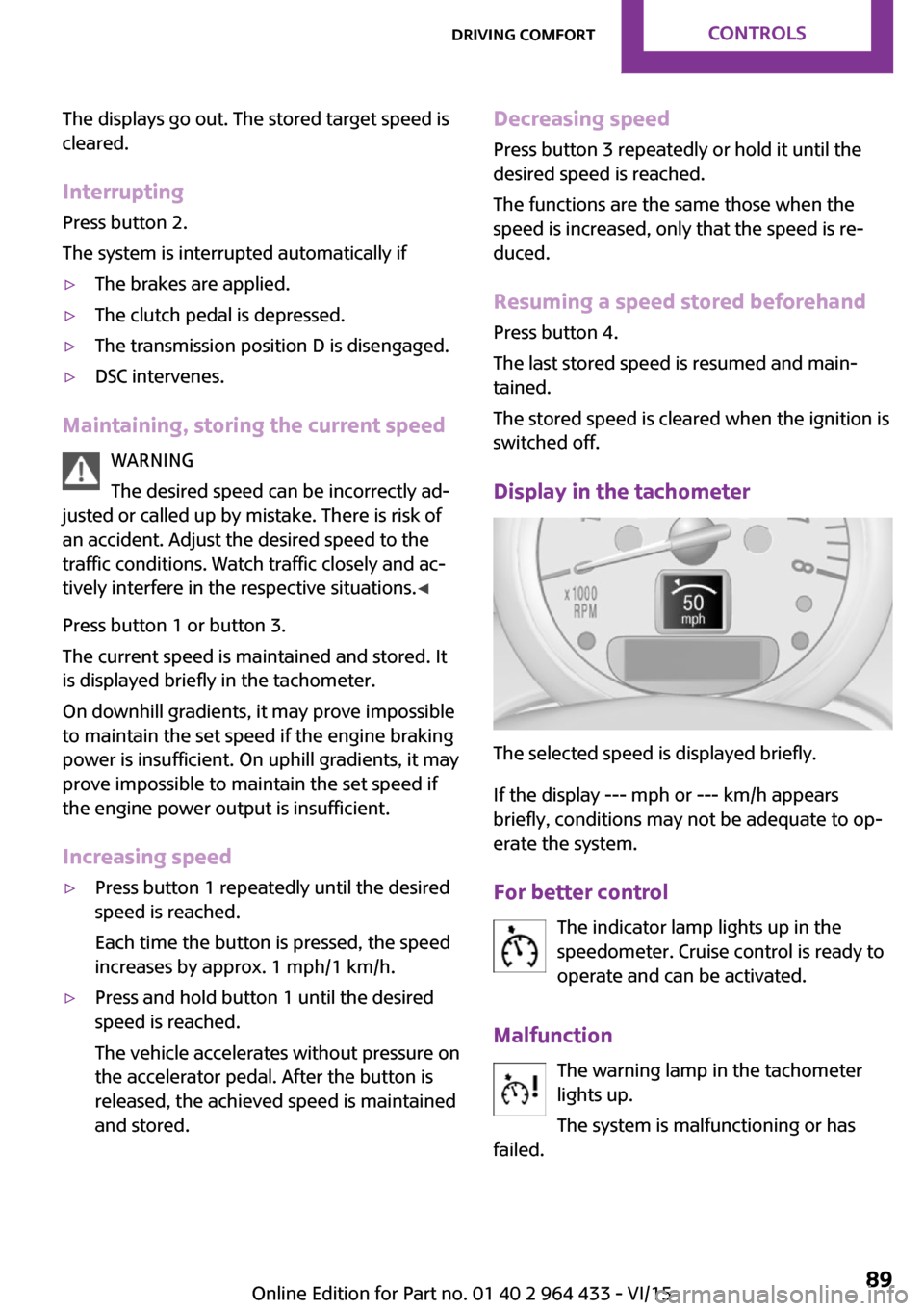
The current speed is maintained and stored. It
is displayed briefly in the tachometer.
On downhill gradients, it may prove impossible
to maintain the set speed if the engine braking
power is insufficient. On uphill gradients, it may
prove impossible to maintain the set speed if
the engine power output is insufficient.
Increasing speed
▷Press button 1 repeatedly until the desired
speed is reached.
Each time the button is pressed, the speed
increases by approx. 1 mph/1 km/h.▷Press and hold button 1 until the desired
speed is reached.
The vehicle accelerates without pressure on
the accelerator pedal. After the button is
released, the achieved speed is maintained
and stored.Decreasing speed
Press button 3 repeatedly or hold it until the
desired speed is reached.
The functions are the same those when the
speed is increased, only that the speed is re‐
duced.
Resuming a speed stored beforehand Press button 4.
The last stored speed is resumed and main‐
tained.
The stored speed is cleared when the ignition is
switched off.
Display in the tachometer
The selected speed is displayed briefly.
If the display --- mph or --- km/h appears
briefly, conditions may not be adequate to op‐
erate the system.
For better control The indicator lamp lights up in the
speedometer. Cruise control is ready to
operate and can be activated.
Malfunction The warning lamp in the tachometer
lights up.
The system is malfunctioning or has
failed.
Seite 89Driving comfortCONTROLS89
Online Edition for Part no. 01 40 2 964 433 - VI/15
Page 90 of 223

Park Distance Control
PDC
The concept
PDC provides support when parking in reverse.
Signal tones indicate that the vehicle is ap‐
proaching an object behind it. Measurements
are made by four ultrasound sensors in the
bumpers.
The range of these sensors is approx. 6 ft/2 m.
An acoustic warning is first given:▷By the two corner sensors at ap‐
prox. 24 in/60 cm.▷By the rear middle sensors at approx.
5 ft/1.50 m.
WARNING
Due to high speeds when PDC is acti‐
vated, the warning can be delayed due to phys‐
ical circumstances. There is risk of injuries or
risk of property damage. Avoid approaching an
object quickly. Avoid driving away quickly while
PDC is not yet active. ◀
Automatic operation
The system is activated after approx. one sec‐
ond when reverse gear or selector lever posi‐
tion R is engaged while the engine is running or
the ignition is switched on. Await this short pe‐
riod before setting the vehicle into motion.
Signal tones
The closer the vehicle is to the object, the
shorter the intervals become. If the distance to
a detected object is less than approx.
12 in/30 cm, a continuous tone is sounded.
If the distance remains constant, for example
when driving parallel to a wall, the signal tone
is stopped after approx. 3 seconds.
Volume
The signal tone volume can be adjusted.
Radio MINI Boost CD, refer to page 126.
System limits
WARNING
The system does not relieve from the per‐
sonal responsibility to correctly assess the traf‐
fic situation. There is risk of an accident. Adjust
the driving style to the traffic conditions. Watch
traffic and vehicle surroundings closely and ac‐
tively interfere in the respective situations. ◀
Malfunction The warning light lights up. PDC is mal‐
functioning or has failed. Have the sys‐
tem checked.
To ensure full functionality of the sensors, keep
the sensors clean and free of ice. When using
high-pressure washers, do not spray the sen‐
sors for long periods and maintain a distance of
at least 12 in/30 cm.Seite 90CONTROLSDriving comfort90
Online Edition for Part no. 01 40 2 964 433 - VI/15
Page 98 of 223
Canada: if the LED does not flash rapidly af‐
ter approx. 60 seconds, change the dis‐
tance and repeat the step. If programming
was aborted by the hand-held transmitter,
hold down the memory button and press
and release the button on the hand-held
transmitter several times for 2 seconds.
Controls
WARNING
Body parts can be jammed when operat‐
ing remote-controlled systems, e.g. the garage
door, using the universal garage door opener.
There is risk of injuries or risk of property dam‐
age. Make sure that the area of movement of
the respective system is clear during program‐
ming and operation. Also follow the safety in‐
structions of the hand-held transmitter. ◀
The system, such as the garage door, can be
operated using the button on the interior rear‐
view mirror with the engine running or the igni‐
tion switched on. When you are within the re‐
ception range of the system, press and hold the
button until the function is initiated. The LED on
the interior rearview mirror lights up continu‐
ously while the radio signal is being transmit‐
ted.
Deleting stored functions
Press the right and left buttons on the interior
rearview mirror simultaneously for approx.
20 seconds until the LED flashes rapidly. All
stored functions are deleted. The functions can‐
not be deleted individually.
Sun visor Glare protection
Folding down
Fold the sun visor down.
Folding up
Fold the sun visor up.
Glare protection from the side
Folding down1.Fold the sun visor down.2.Detach from the holder and pivot sideways
to the side window.
Folding up
To close the sun visor, proceed in reverse order.
Vanity mirror A vanity mirror is located behind a cover on
each sun visor.
To open, fold the cover up.
Depending on the vehicle equipment, mirror
lighting comes on when the cover is opened.
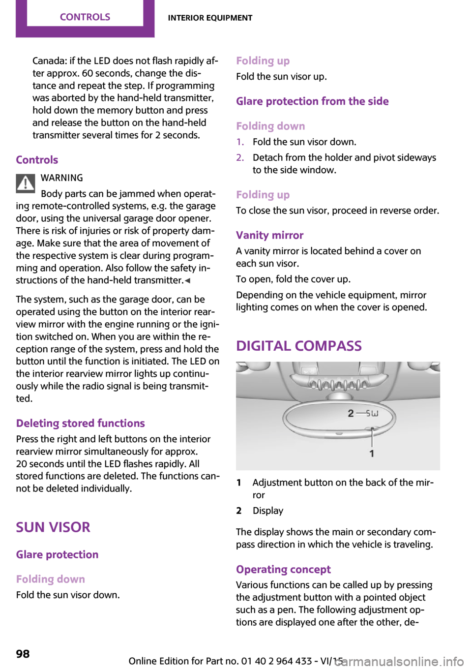
Digital compass
1Adjustment button on the back of the mir‐
ror2Display
The display shows the main or secondary com‐
pass direction in which the vehicle is traveling.
Operating concept
Various functions can be called up by pressing
the adjustment button with a pointed object
such as a pen. The following adjustment op‐
tions are displayed one after the other, de‐
Seite 98CONTROLSInterior equipment98
Online Edition for Part no. 01 40 2 964 433 - VI/15
Page 170 of 223
CoolantVehicle features and op‐
tions
This chapter describes all standard, country-
specific and optional features offered with the
series. It also describes features that are not
necessarily available in your car, e. g., due to
the selected options or country versions. This
also applies to safety-related functions and sys‐
tems.
When using the features and systems described
here, adhere to local regulations.
General information WARNING
With the engine hot and the cooling sys‐
tem open, coolant can escape and lead to
burns. There is risk of injuries. Only open the
cooling system with the engine cooled down. ◀
WARNING
Additives are harmful and incorrect addi‐
tives can damage the engine. There is risk of in‐
juries and risk of property damage. Avoid the
contact of articles of clothing, skin or eyes with
additives. Do not swallow any additives. Use
suitable additives only. ◀
Coolant consists of water and additives. Not all commercially available additives are
suitable for the vehicle. Information regarding
suitable additives is available from a dealer’s
service center or another qualified service cen‐
ter or repair shop.Coolant temperature
If the coolant and therefore the engine over‐
heat, a warning lamp lights up, refer to
page 194.
Coolant level Checking1.Do not open the hood until the engine has
cooled down.2.Turn the expansion tank cap counterclock‐
wise slightly to allow any accumulated
pressure to escape; then continue turning
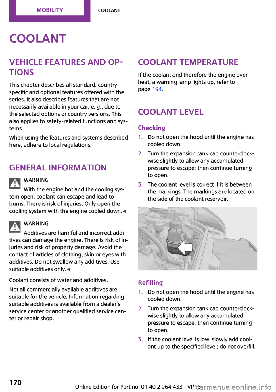
to open.3.The coolant level is correct if it is between
the markings. The markings are located on
the side of the coolant reservoir.
Refilling
1.Do not open the hood until the engine has
cooled down.2.Turn the expansion tank cap counterclock‐
wise slightly to allow any accumulated
pressure to escape, then continue turning
to open.3.If the coolant level is low, slowly add cool‐
ant up to the specified level; do not overfill.Seite 170MOBILITYCoolant170
Online Edition for Part no. 01 40 2 964 433 - VI/15
Page 173 of 223

and Service Guide Booklet for Canadian models
for additional information on service require‐
ments.
The manufacturer of your vehicle recommends
that maintenance and repair be performed by a
dealer’s service center or another qualified
service center or repair shop. Records of regu‐
lar maintenance and repair work should be re‐
tained.
Socket for OBD Onboard
Diagnosis
CAUTION
The socket for Onboard Diagnosis is an
intricate component intended to be used in
conjunction with specialized equipment to
check the vehicle’s primary emissions system.
Improper use of the socket for Onboard Diag‐
nosis, or contact with the socket for Onboard
Diagnosis for other than its intended purpose,
can cause vehicle malfunctions and creates
risks of personal and property damage. Given
the foregoing, the manufacture of your vehicle
strongly recommends that access to the socket
for Onboard Diagnosis be limited to a dealer's
service center or another qualified service cen‐
ter or repair shop or other persons that have
the specialized training and equipment for pur‐
poses of properly utilizing the socket for On‐
board Diagnosis. ◀
Primary components in the vehicle emissions
can be checked via the OBD socket using a de‐
vice.
Emissions
The warning lamps light up. The vehicle
is producing higher emissions. Further
driving at a moderate pace is possible.
Have the vehicle checked as soon as possible.
Under certain circumstances, one of the lamps
flashes or lights up continuously. This indicates
that there is excessive misfiring or a malfunc‐
tion in the engine. In this situation, decrease
the vehicle speed and immediately drive to a
dealer’s service center or another qualified
service center or repair shop. Serious engine
misfiring within a brief period can seriously
damage emission control components, in par‐
ticular the catalytic converter. In addition, the
mechanical engine components may become
damaged.
If the fuel filler cap is not properly tight‐
ened, the OBD system may conclude
that fuel vapor is escaping; this will
cause a display to light up. If the filler cap is
then tightened, the display should go out in a
few days.Seite 173MaintenanceMOBILITY173
Online Edition for Part no. 01 40 2 964 433 - VI/15
Page 175 of 223
3.Press the wiper blade against the stop to
push it out of the fixation.4.Press the new wiper blade into the fixation
until it engages audibly.5.Fold down the wiper arm.
Lamp and bulb replace‐
ment
Information
Lamps and bulbs Lamps and bulbs make an essential contribu‐
tion to vehicle safety. Therefore, exercise cau‐
tion when handling lights and bulbs.
The vehicle manufacturer recommends that
you have the necessary work performed by a
dealer’s service center or another qualified
service center or repair shop if you are unfami‐
liar with it or it is not described here.
A spare lamp box is available from a dealer’s
service center or another qualified service cen‐
ter or repair shop.
WARNING
Bulbs can get hot during operation. Con‐
tact with the bulbs can cause burns. There is
risk of injuries. Only change bulbs after they
have cooled off. ◀
WARNING
Work on switched-on lighting systems
can cause short circuits. There is risk of injuries
or risk of property damage. When working on
the lighting system, switch off the lamps in
question. If necessary, heed the bulb manufac‐
turer's instructions. ◀
CAUTION
Contaminated bulbs reduce their service
life. There is risk of property damage. Do not
hold new bulbs with your bare hands. Use a
clean cloth or something similar, or hold the
bulb by its base. ◀
Caring for the headlights, refer to page 191.
For bulb replacement procedures that are not
described here, contact a dealer’s service cen‐
ter or another qualified service center or repair
shop.
For checking and adjusting headlamp aim, con‐
tact a dealer’s service center or another quali‐
fied service center or repair shop.
Light-emitting diodes LEDs In some equipment, the light source is provided
by light-emitting diodes behind a cover.
These light-emitting diodes, which operate us‐
ing a concept similar to that applied in conven‐
tional lasers, are designated as Class 1 light-
emitting diodes.
WARNING
Too intensive brightness can irritate or
damage the retina of the eye. There is risk of
injuries. Do not look directly into the headlights
or other light sources for an extended period of
time. Do not remove the LED covers. ◀
Headlight glass
Condensation can form on the inside of the ex‐
ternal lights in cool or humid weather. When
you drive with the lights switched on, the con‐
densation evaporates after a short time. The
headlight glass does not need to be changed.
If despite driving with the lights switched on,
increasing humidity forms, e. g. water droplets
in the lamp, the manufacturer of your vehicle
recommends having it checked by a dealer’s
service center or another qualified service cen‐
ter or repair shop.
Bi-xenon headlights
These bulbs have a very long life and the likeli‐
hood of failure is very low, provided that they
are not switched on and off excessively. If a
bulb should nevertheless fail, you can continueSeite 175Replacing componentsMOBILITY175
Online Edition for Part no. 01 40 2 964 433 - VI/15
Page 187 of 223
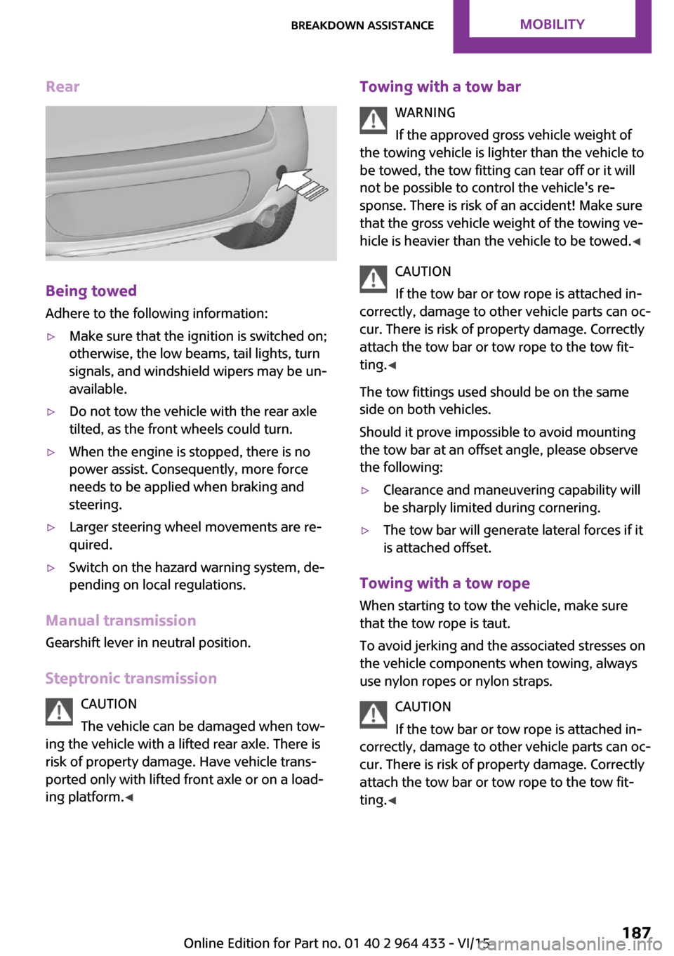
Rear
Being towed
Adhere to the following information:
▷Make sure that the ignition is switched on;
otherwise, the low beams, tail lights, turn
signals, and windshield wipers may be un‐
available.▷Do not tow the vehicle with the rear axle
tilted, as the front wheels could turn.▷When the engine is stopped, there is no
power assist. Consequently, more force
needs to be applied when braking and
steering.▷Larger steering wheel movements are re‐
quired.▷Switch on the hazard warning system, de‐
pending on local regulations.
Manual transmission
Gearshift lever in neutral position.
Steptronic transmission CAUTION
The vehicle can be damaged when tow‐
ing the vehicle with a lifted rear axle. There is
risk of property damage. Have vehicle trans‐
ported only with lifted front axle or on a load‐
ing platform. ◀
Towing with a tow bar
WARNING
If the approved gross vehicle weight of
the towing vehicle is lighter than the vehicle to
be towed, the tow fitting can tear off or it will
not be possible to control the vehicle's re‐
sponse. There is risk of an accident! Make sure
that the gross vehicle weight of the towing ve‐
hicle is heavier than the vehicle to be towed. ◀
CAUTION
If the tow bar or tow rope is attached in‐
correctly, damage to other vehicle parts can oc‐
cur. There is risk of property damage. Correctly
attach the tow bar or tow rope to the tow fit‐
ting. ◀
The tow fittings used should be on the same
side on both vehicles.
Should it prove impossible to avoid mounting
the tow bar at an offset angle, please observe
the following:▷Clearance and maneuvering capability will
be sharply limited during cornering.▷The tow bar will generate lateral forces if it
is attached offset.
Towing with a tow rope
When starting to tow the vehicle, make sure
that the tow rope is taut.
To avoid jerking and the associated stresses on
the vehicle components when towing, always
use nylon ropes or nylon straps.
CAUTION
If the tow bar or tow rope is attached in‐
correctly, damage to other vehicle parts can oc‐ cur. There is risk of property damage. Correctly
attach the tow bar or tow rope to the tow fit‐ ting. ◀
Seite 187Breakdown assistanceMOBILITY187
Online Edition for Part no. 01 40 2 964 433 - VI/15
Page 191 of 223
▷Insert the remote control into the ignition
lock.
Steptronic transmission
Before driving into the car wash, note the fol‐
lowing to ensure that the vehicle can roll:
1.Insert the remote control into the ignition
lock, even with Comfort Access.2.Move the selector lever to position N.3.Release the parking brake.4.Switch the engine off.5.Leave the remote control in the ignition
lock so that the vehicle can roll.
Hand car wash
If washing the vehicle by hand, use copious
quantities of water and car shampoo if neces‐
sary. Clean the vehicle with a sponge or a
washing brush by applying gentle pressure.
Before cleaning the windshield, deactivate the
rain sensor to avoid unintentional wiper activa‐
tion or switch off the ignition.
Adhere to the local regulations regarding
washing cars by hand.
Headlights Do not rub dry and do not use abrasive or caus‐
tic cleansers. Soak areas that have been soiled,
e.g., due to insects, with shampoo and rinse off
with copious quantities of water.
Thaw ice with a window deicer; do not use an
ice scraper.
Windows
Clean the outside and inside surfaces of the
windows and the mirror glasses with window
cleaner.
Do not clean mirror glass with cleaners contain‐
ing quartz.
Wiper blades
Clean with soapy water and replace regularly to
avoid streaking.
Wax and preservative residue and soiling on
the windows cause streaking during window
wiping and lead to premature wear on the
wiper blades and malfunctions of the rain sen‐
sor.
Vehicle care
Car care products
Regular cleaning and care contributes signifi‐
cantly to vehicle value retention.
The manufacturer of your vehicle recommends using car care and cleaning products from
MINI.
WARNING
Cleansers can contain substances that are
dangerous and harmful to your health. There is
risk of injuries. When cleaning the interior, open
the doors or windows. Only use products in‐
tended for cleaning vehicles. Follow the instruc‐
tions on the container. ◀
Vehicle paint Regular care contributes to vehicle value reten‐
tion and protects the paintwork against the
long-term effects of paint-damaging substan‐
ces.
Environmental influences in areas with higher
air pollution or natural contaminants, such as
tree resin or pollen, can have an impact on the
vehicle paint. Therefore, it is important to tailor
the frequency and extent of your car care to
these influences.
Immediately remove especially aggressive sub‐
stances, such as spilled fuel, oil, grease, or bird
droppings, to prevent damage to the paint‐
work.Seite 191CareMOBILITY191
Online Edition for Part no. 01 40 2 964 433 - VI/15
Page 194 of 223

Indicator/warning lampsVehicle features and op‐
tions
This chapter describes all standard, country-
specific and optional features offered with the
series. It also describes features that are notnecessarily available in your car, e. g., due to
the selected options or country versions. This
also applies to safety-related functions and sys‐
tems.
When using the features and systems described
here, adhere to local regulations.
Overview
The indicator and warning lights can light up in
a variety of combinations and colors in display
area 1 or 2. The table contains information on
causes and how to respond. Note whether a
lamp lights up alone or in combination with an‐
other. Some lights can light up in different col‐
ors. Corresponding distinctions are made in the
text. 12CauseHow to respondTurn signalThe high-beams/headlight flasher are
switched on.The front fog lamps are switched on.The rear fog lights are switched on.Fasten safety belts.Fasten safety belt, refer to page 41.External temperature warningDrive conservatively, refer to
page 61.Seite 194MOBILITYIndicator/warning lamps194
Online Edition for Part no. 01 40 2 964 433 - VI/15