buttons MINI Paceman 2016 Owner's Manual (Mini Connected)
[x] Cancel search | Manufacturer: MINI, Model Year: 2016, Model line: Paceman, Model: MINI Paceman 2016Pages: 223, PDF Size: 5.52 MB
Page 13 of 223
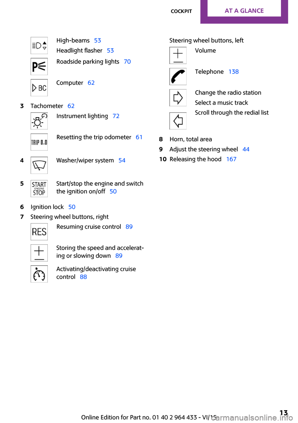
High-beams 53
Headlight flasher 53Roadside parking lights 70Computer 623Tachometer 62Instrument lighting 72Resetting the trip odometer 614Washer/wiper system 545Start/stop the engine and switch
the ignition on/off 506Ignition lock 507Steering wheel buttons, rightResuming cruise control 89Storing the speed and accelerat‐
ing or slowing down 89Activating/deactivating cruise
control 88Steering wheel buttons, leftVolumeTelephone 138Change the radio station
Select a music track
Scroll through the redial list8Horn, total area9Adjust the steering wheel 4410Releasing the hood 167Seite 13CockpitAT A GLANCE13
Online Edition for Part no. 01 40 2 964 433 - VI/15
Page 15 of 223
Indicator/warning lights
The principle
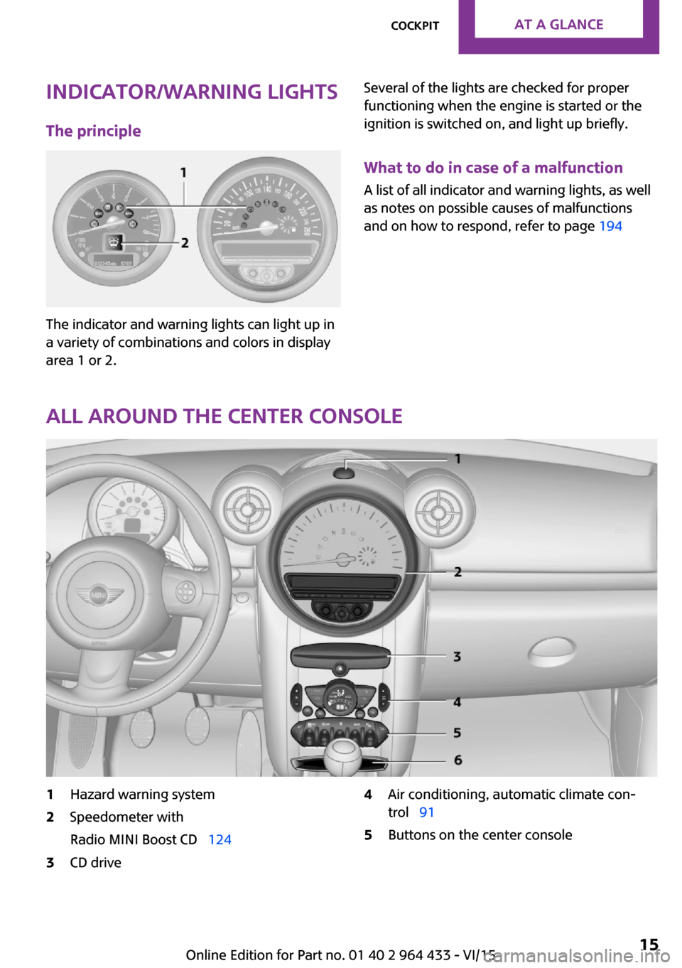
The indicator and warning lights can light up in
a variety of combinations and colors in display
area 1 or 2.
Several of the lights are checked for proper
functioning when the engine is started or the
ignition is switched on, and light up briefly.
What to do in case of a malfunction
A list of all indicator and warning lights, as well
as notes on possible causes of malfunctions
and on how to respond, refer to page 194
All around the center console
1Hazard warning system2Speedometer with
Radio MINI Boost CD 1243CD drive4Air conditioning, automatic climate con‐
trol 915Buttons on the center consoleSeite 15CockpitAT A GLANCE15
Online Edition for Part no. 01 40 2 964 433 - VI/15
Page 20 of 223
Opening and closingVehicle features and op‐
tions
This chapter describes all standard, country-
specific and optional features offered with the
series. It also describes features that are not
necessarily available in your car, e. g., due to
the selected options or country versions. This
also applies to safety-related functions and sys‐
tems.
When using the features and systems described
here, adhere to local regulations.
Remote control/key
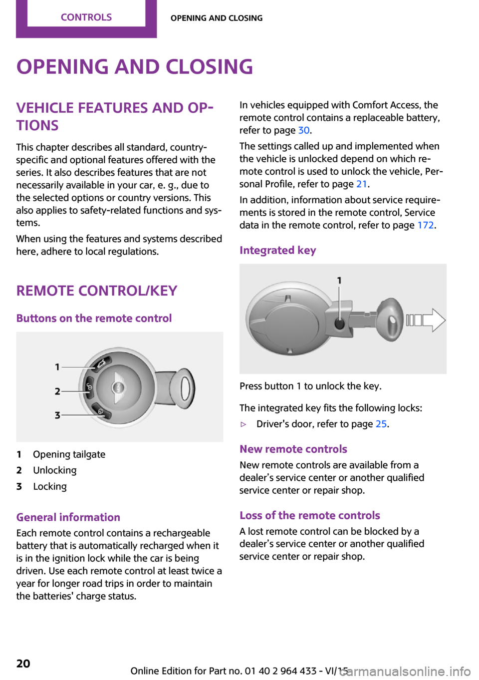
Buttons on the remote control1Opening tailgate2Unlocking3Locking
General information
Each remote control contains a rechargeable
battery that is automatically recharged when it
is in the ignition lock while the car is being
driven. Use each remote control at least twice a
year for longer road trips in order to maintain
the batteries' charge status.
In vehicles equipped with Comfort Access, the
remote control contains a replaceable battery,
refer to page 30.
The settings called up and implemented when
the vehicle is unlocked depend on which re‐
mote control is used to unlock the vehicle, Per‐
sonal Profile, refer to page 21.
In addition, information about service require‐
ments is stored in the remote control, Service
data in the remote control, refer to page 172.
Integrated key
Press button 1 to unlock the key.
The integrated key fits the following locks:
▷Driver's door, refer to page 25.
New remote controls
New remote controls are available from a
dealer’s service center or another qualified
service center or repair shop.
Loss of the remote controls A lost remote control can be blocked by a
dealer’s service center or another qualified
service center or repair shop.
Seite 20CONTROLSOpening and closing20
Online Edition for Part no. 01 40 2 964 433 - VI/15
Page 21 of 223
Personal Profile
The concept
You can set several of your vehicle's functions
to suit your personal needs and preferences.▷Through Personal Profile, most of these set‐
tings are stored for the remote control cur‐
rently in use.▷While the vehicle is being unlocked, the re‐
mote control is recognized and the settings
stored with it are called up and imple‐
mented.▷Your personal settings will be recognized
and called up again even if the vehicle has
been used in the meantime by someone
else with another remote control.▷The individual settings are stored for no
more than three remote controls.
Personal Profile settings
The following functions and settings can be
stored in a profile.
More information on the settings can be found
under:
▷Response of the central locking system
when the car is being unlocked, refer to
page 22.▷Automatic locking of the vehicle, refer to
page 26.▷Triple turn signal activation, refer to
page 53.▷Settings for the displays in the speedometer
and tachometer:▷12h/24h clock format, refer to
page 64.▷Date format, refer to page 64.▷Units of measure for fuel consumption,
distance covered/remaining distances,
and temperature, refer to page 64.▷Light settings:▷Headlight courtesy delay feature, refer
to page 71.▷Daytime running lights, refer to
page 70.▷Automatic climate control, refer to
page 93: AUTO program, activating/deac‐
tivating the cooling function, setting the
temperature, air volume, and air distribu‐
tion.▷Entertainment:▷Last entertainment source.▷Radio MINI Boost CD:
Tone settings, refer to page 126.
Volume, refer to page 126.
Central locking system
The concept
The central locking system becomes active
when the driver's door is closed.
The system simultaneously engages and re‐
leases the locks on the following:
▷Doors.▷Tailgate.▷Fuel filler flap.
Operating from the outside
▷Via the remote control.▷Via the door lock.▷In cars with Comfort Access, via the door
handles on the driver's and front passenger
sides.
The following takes place simultaneously when
locking/unlocking the vehicle via the remote
control:
▷Depending on the vehicle equipment, the
anti-theft protection is switched on and off
as well. The anti-theft protection makes it
impossible to unlock the doors using the
lock buttons or door handles.Seite 21Opening and closingCONTROLS21
Online Edition for Part no. 01 40 2 964 433 - VI/15
Page 26 of 223

The graphic shows the button in the MINI Pace‐
man as an example.
The switch or the buttons can be used to lock
or unlock the doors and tailgate when the
doors are closed, but they are not theft-pro‐
tected. The fuel filler flap remains unlocked.
Unlocking and opening doors
▷Using the switch or the buttons for the cen‐
tral locking system, unlock all of the doors
at once and then pull the door opener
above the armrest, or▷Pull the door handle on each door twice:
the door is unlocked the first time and
opened the second time.
Locking
▷Press the switch/button or▷Push down the lock button of a door. To
avoid locking yourself out by accident, the
driver's door cannot be locked at the lock
button while the door is open.Automatic locking
In addition, it is possible to set the situations in
which the vehicle locks. The setting is stored for
the remote control in use.1.Switch on the ignition, refer to page 50.2.Press the button on the turn indicator lever
repeatedly until "SET/INFO" is displayed.3.Press and hold the button until the display
changes.4.Press the button repeatedly until the sym‐
bol and "SET" are displayed.5.Press and hold the button until the display
changes.6.Press the button repeatedly until the sym‐
bol shown is displayed, arrow.Seite 26CONTROLSOpening and closing26
Online Edition for Part no. 01 40 2 964 433 - VI/15
Page 28 of 223
Press the button on the remote control
for approx. 1 second and release. The tailgate is
unlocked.
Closing WARNING
Body parts can be jammed when operat‐
ing the tailgate. There is risk of injuries. Make
sure that the area of movement of the tailgate
is clear during opening and closing. ◀
Make sure that the cargo cover rests on the
rubber buffers of the securing straps when clos‐
ing the tailgate.
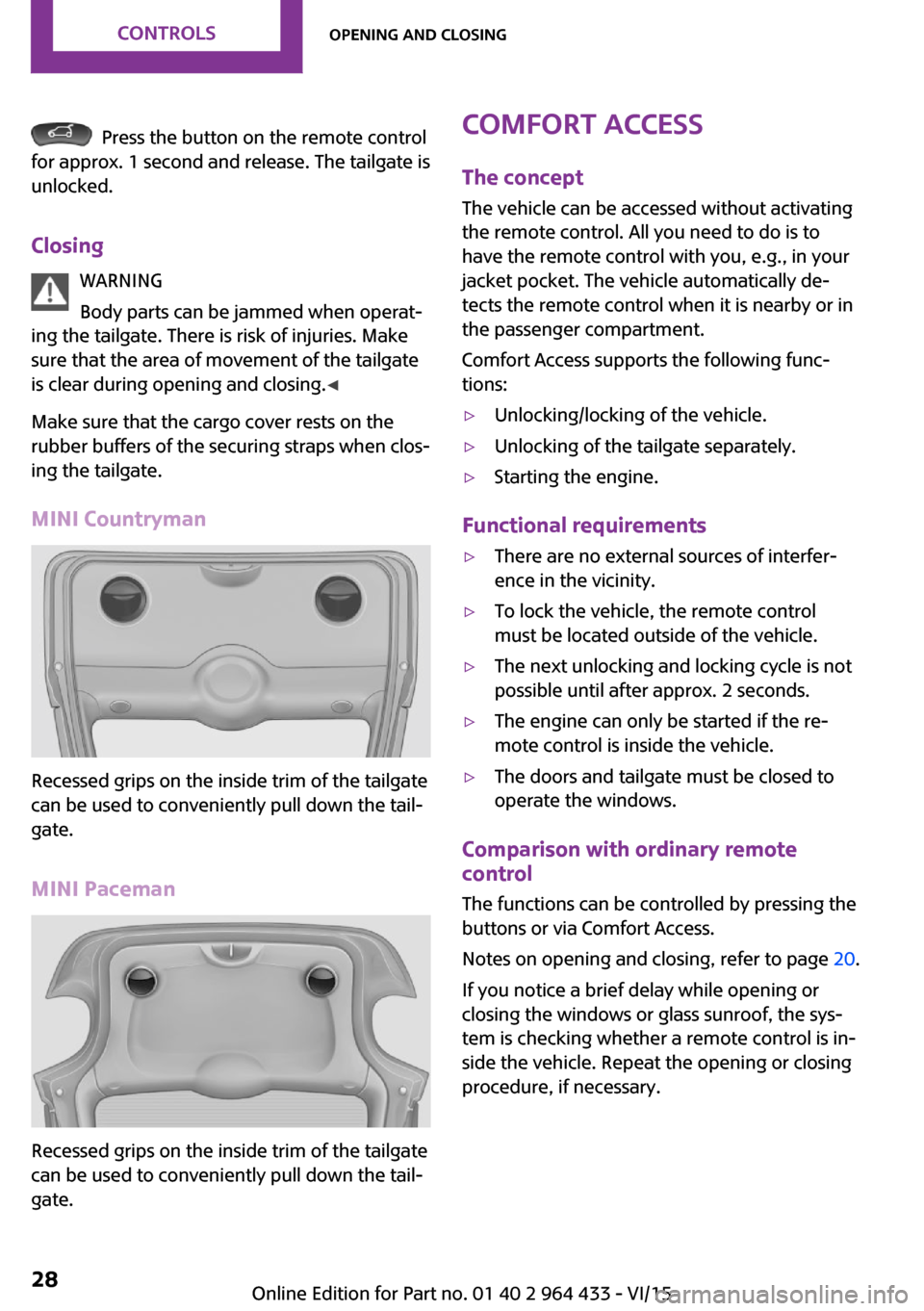
MINI Countryman
Recessed grips on the inside trim of the tailgate
can be used to conveniently pull down the tail‐
gate.
MINI Paceman
Recessed grips on the inside trim of the tailgate
can be used to conveniently pull down the tail‐
gate.
Comfort Access
The concept
The vehicle can be accessed without activating
the remote control. All you need to do is to have the remote control with you, e.g., in your
jacket pocket. The vehicle automatically de‐
tects the remote control when it is nearby or in
the passenger compartment.
Comfort Access supports the following func‐
tions:▷Unlocking/locking of the vehicle.▷Unlocking of the tailgate separately.▷Starting the engine.
Functional requirements
▷There are no external sources of interfer‐
ence in the vicinity.▷To lock the vehicle, the remote control
must be located outside of the vehicle.▷The next unlocking and locking cycle is not
possible until after approx. 2 seconds.▷The engine can only be started if the re‐
mote control is inside the vehicle.▷The doors and tailgate must be closed to
operate the windows.
Comparison with ordinary remote
control
The functions can be controlled by pressing the
buttons or via Comfort Access.
Notes on opening and closing, refer to page 20.
If you notice a brief delay while opening or
closing the windows or glass sunroof, the sys‐
tem is checking whether a remote control is in‐
side the vehicle. Repeat the opening or closing
procedure, if necessary.
Seite 28CONTROLSOpening and closing28
Online Edition for Part no. 01 40 2 964 433 - VI/15
Page 30 of 223
control or when a mobile phone is being
charged in the vehicle.
If this occurs, open or close the vehicle using
the buttons on the remote control or use the
integrated key in the door lock.
To start the engine afterward, insert the remote
control into the ignition switch.
Warning lights The warning light in the instrument
cluster lights up when you attempt to
start the engine: the engine cannot be
started.
The remote control is not in the vehicle or has a
malfunction. Take the remote control with you
inside the vehicle or have it checked. If neces‐
sary, insert another remote control into the ig‐
nition switch.
The warning lamp in the instrument
cluster lights up while the engine is run‐
ning: the remote control is no longer in‐
side the vehicle.
After switching off the engine, the engine can
only be started again within approx. 10 sec‐
onds if no door has been opened.
The indicator lamp lights up: replace
the remote control battery.Replacing the battery
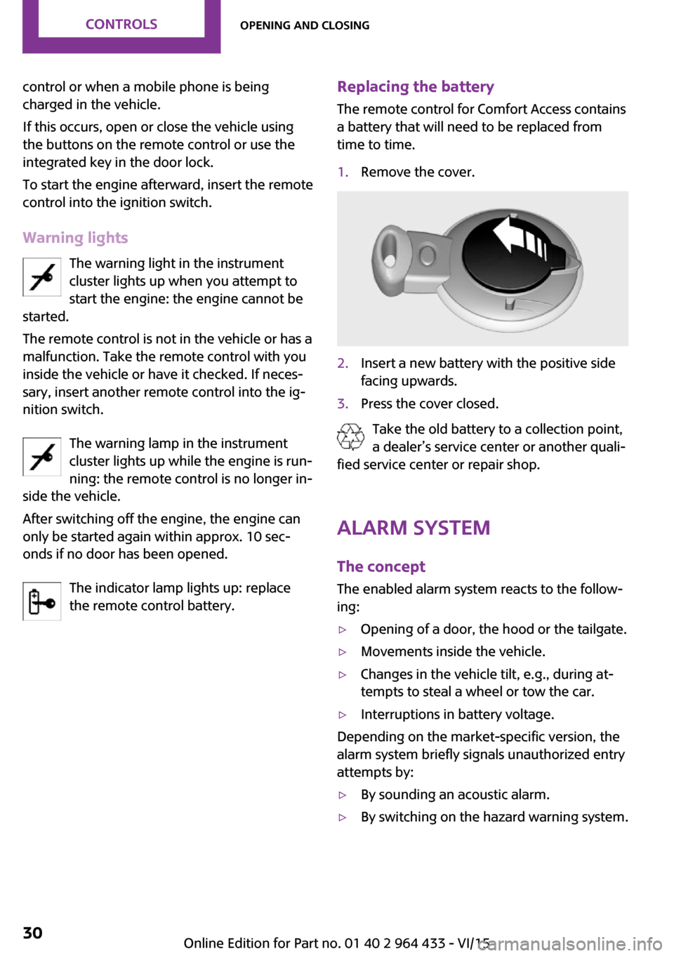
The remote control for Comfort Access contains
a battery that will need to be replaced from
time to time.1.Remove the cover.2.Insert a new battery with the positive side
facing upwards.3.Press the cover closed.
Take the old battery to a collection point,
a dealer’s service center or another quali‐
fied service center or repair shop.
Alarm system
The concept
The enabled alarm system reacts to the follow‐
ing:
▷Opening of a door, the hood or the tailgate.▷Movements inside the vehicle.▷Changes in the vehicle tilt, e.g., during at‐
tempts to steal a wheel or tow the car.▷Interruptions in battery voltage.
Depending on the market-specific version, the
alarm system briefly signals unauthorized entry
attempts by:
▷By sounding an acoustic alarm.▷By switching on the hazard warning system.Seite 30CONTROLSOpening and closing30
Online Edition for Part no. 01 40 2 964 433 - VI/15
Page 96 of 223
Interior equipmentVehicle features and op‐
tions
This chapter describes all standard, country-
specific and optional features offered with the
series. It also describes features that are not
necessarily available in your car, e. g., due to
the selected options or country versions. This
also applies to safety-related functions and sys‐
tems.
When using the features and systems described
here, adhere to local regulations.
Universal garage door
opener
The concept
The universal garage door opener can be used
to operate up to 3 functions in remote-control‐
led systems, such as garage door drives or
lighting systems. The universal garage door
opener replaces up to 3 different hand-held
transmitters. To operate it, the buttons on the
interior rearview mirror must be programmed
for the desired functions. The hand-held trans‐
mitter for the system is needed for the pro‐
gramming procedure.
WARNING
Body parts can be jammed when operat‐
ing remote-controlled systems, e.g. the garage
door, using the universal garage door opener.
There is risk of injuries or risk of property dam‐
age. Make sure that the area of movement of
the respective system is clear during program‐
ming and operation. Also follow the safety in‐
structions of the hand-held transmitter. ◀
Before selling the vehicle, delete the stored
functions for security reasons.Compatibility
If this symbol is printed on the packag‐
ing or in the operating instructions of
the system being operated, the system
is generally compatible with the universal ga‐
rage door opener.
If you have any questions, please contact:▷A dealer’s service center or another quali‐
fied service center or repair shop.▷www.homelink.com on the Internet.
HomeLink is a registered trademark of the
Gentex Corporation.
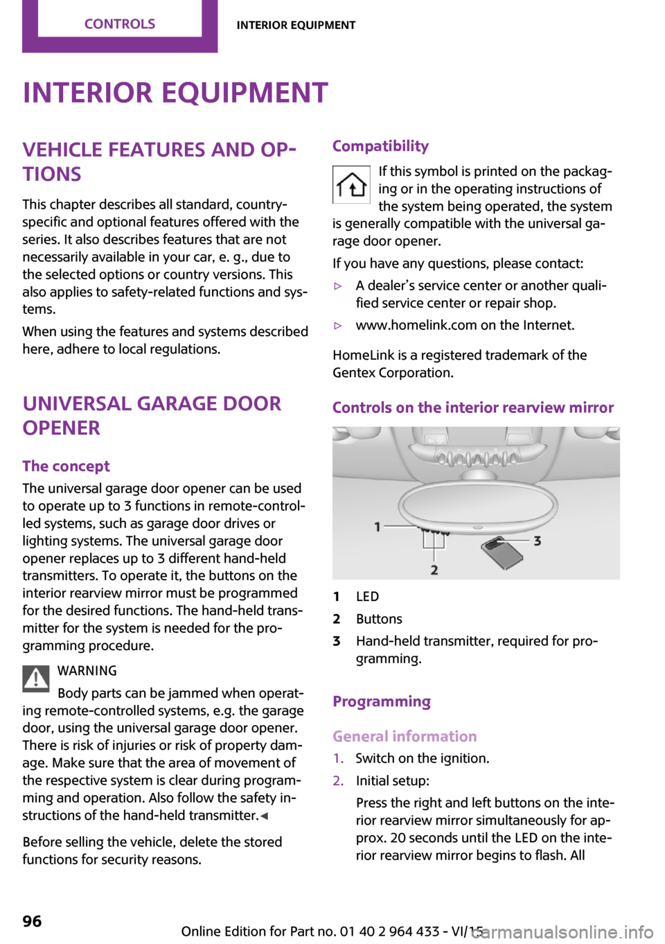
Controls on the interior rearview mirror
1LED2Buttons3Hand-held transmitter, required for pro‐
gramming.
Programming
General information
1.Switch on the ignition.2.Initial setup:
Press the right and left buttons on the inte‐
rior rearview mirror simultaneously for ap‐
prox. 20 seconds until the LED on the inte‐
rior rearview mirror begins to flash. AllSeite 96CONTROLSInterior equipment96
Online Edition for Part no. 01 40 2 964 433 - VI/15
Page 97 of 223
programmed settings of the buttons on the
interior rearview mirror are deleted.3.Hold the hand-held transmitter of the sys‐
tem to be operated a distance of approx. 1
to 3 in/2.5 to 8 cm away from the buttons
on the interior rearview mirror. The re‐
quired distance depends on the particular
hand-held transmitter.4.Press the button of the desired function on
the hand-held transmitter and the button
being programmed on the interior rearview
mirror simultaneously and hold. The LED on
the interior rearview mirror flashes slowly at
first.5.When the LED flashes more rapidly, release
both buttons. Rapid flashing indicates that
the button on the interior rearview mirror
has been programmed.
If the LED does not flash faster after 60 sec‐
onds, change the distance between the in‐
terior rearview mirror and the hand-held
transmitter and repeat the step. Multiple
trials at different distances may be neces‐
sary. Wait at least 15 seconds between tri‐
als.6.To program additional functions on other
buttons, repeat steps 3 to 5.
The systems can be operated with the buttons
on the interior rearview mirror.
Special characteristics of alternating-
code radio systems
If the system cannot be operated after re‐
peated programming, check whether the sys‐
tem to be operated uses an alternating-code
system.
Read the operating instructions of the system
or press and hold the programmed button on
the interior rearview mirror. If the LED on the
interior rearview mirror flashes rapidly at first
and then lights up continuously for 2 seconds,
the system is equipped with an alternating-
code system. This flashing LED pattern repeats
itself for approx. 20 seconds.
In systems with an alternating-code system, the
universal garage door opener and the system
must be additionally synchronized.
Please obtain additional information on syn‐
chronization in the operating instructions of the
system being set up.
The systems will be easier to synchronize with
the aid of a second person.
Synchronization:1.Park the vehicle within range of the re‐
mote-controlled system.2.Program the corresponding button on the
interior rearview mirror as described.3.Identify and press the synchronization but‐
ton on the system being set up. You have
approx. 30 seconds for the next step.4.Press and hold the button on the interior
rearview mirror for approx. 3 seconds and
then release it. Repeat this step up to three
times if necessary to complete the synchro‐
nization procedure. When synchronization
is completed, the programmed function is
executed.
Reprogramming individual buttons
1.Switch on the ignition.2.Hold the hand-held transmitter at a dis‐
tance of approx. 1 to 3 in/2.5 to 8 cm from
the memory buttons.
The required distance depends on the par‐
ticular hand-held transmitter.3.Press the memory button of the universal
garage door opener.4.If the LED flashes slowly after approx.
20 seconds, press the transmit button on
the hand-held transmitter.5.Release both buttons when the LED flashes
rapidly.
If the LED does not flash rapidly after ap‐
prox. 60 seconds, change the distance and
repeat the step.Seite 97Interior equipmentCONTROLS97
Online Edition for Part no. 01 40 2 964 433 - VI/15
Page 98 of 223
Canada: if the LED does not flash rapidly af‐
ter approx. 60 seconds, change the dis‐
tance and repeat the step. If programming
was aborted by the hand-held transmitter,
hold down the memory button and press
and release the button on the hand-held
transmitter several times for 2 seconds.
Controls
WARNING
Body parts can be jammed when operat‐
ing remote-controlled systems, e.g. the garage
door, using the universal garage door opener.
There is risk of injuries or risk of property dam‐
age. Make sure that the area of movement of
the respective system is clear during program‐
ming and operation. Also follow the safety in‐
structions of the hand-held transmitter. ◀
The system, such as the garage door, can be
operated using the button on the interior rear‐
view mirror with the engine running or the igni‐
tion switched on. When you are within the re‐
ception range of the system, press and hold the
button until the function is initiated. The LED on
the interior rearview mirror lights up continu‐
ously while the radio signal is being transmit‐
ted.
Deleting stored functions
Press the right and left buttons on the interior
rearview mirror simultaneously for approx.
20 seconds until the LED flashes rapidly. All
stored functions are deleted. The functions can‐
not be deleted individually.
Sun visor Glare protection
Folding down
Fold the sun visor down.
Folding up
Fold the sun visor up.
Glare protection from the side
Folding down1.Fold the sun visor down.2.Detach from the holder and pivot sideways
to the side window.
Folding up
To close the sun visor, proceed in reverse order.
Vanity mirror A vanity mirror is located behind a cover on
each sun visor.
To open, fold the cover up.
Depending on the vehicle equipment, mirror
lighting comes on when the cover is opened.
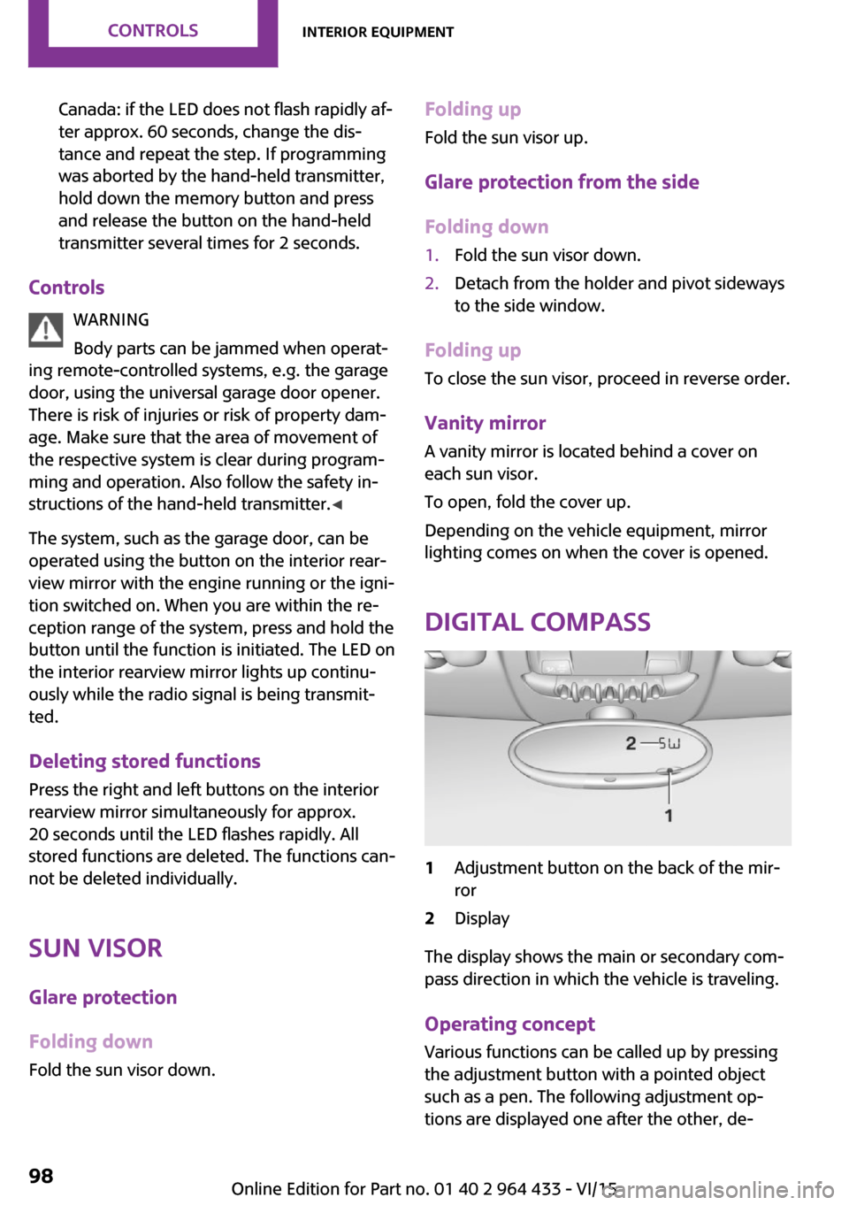
Digital compass
1Adjustment button on the back of the mir‐
ror2Display
The display shows the main or secondary com‐
pass direction in which the vehicle is traveling.
Operating concept
Various functions can be called up by pressing
the adjustment button with a pointed object
such as a pen. The following adjustment op‐
tions are displayed one after the other, de‐
Seite 98CONTROLSInterior equipment98
Online Edition for Part no. 01 40 2 964 433 - VI/15