parking brake MINI Paceman 2016 Owner's Manual (Mini Connected)
[x] Cancel search | Manufacturer: MINI, Model Year: 2016, Model line: Paceman, Model: MINI Paceman 2016Pages: 223, PDF Size: 5.52 MB
Page 32 of 223
Interior motion sensorFor the interior motion sensor to function prop‐
erly, the windows and the glass sunroof must be closed.
Avoiding unintentional alarms
The tilt alarm sensor and interior motion sensor
can be switched off together, such as in the fol‐
lowing situations:▷In duplex garages.▷During transport on car-carrying trains, at
sea or on a trailer.▷When animals are to remain in the vehicle.
Switching off the tilt alarm sensor and
interior motion sensor
▷ Press the button on the remote
control twice in succession.▷Lock the vehicle twice with the integrated
key.
The LEDs flash in short succession for approx.
2 seconds. The tilt alarm sensor and interior
motion sensor remain switched off until the ve‐
hicle is unlocked and locked again.
Glass sunroof, electrical
General information WARNING
Body parts can be jammed on operating
the glass sunroof. There is risk of injuries. Make
sure that the area of movement of the glass
sunroof is clear during opening and closing. ◀
WARNING
Unattended children or animals can move
the vehicle and endanger themselves and traf‐
fic, e.g. with the following actions:
▷Pressing the Start/Stop button.▷Releasing the parking brake.▷Opening and closing of doors or windows.▷Shifting the selector lever into neutral.▷Using vehicle equipment.
There is risk of accidents or injuries. Do not
leave children or animals unattended in the ve‐
hicle. Carry remote control along when exiting
and lock the vehicle. ◀
Convenient operation via:
▷Door lock, refer to page 25▷Comfort Access, refer to page 29
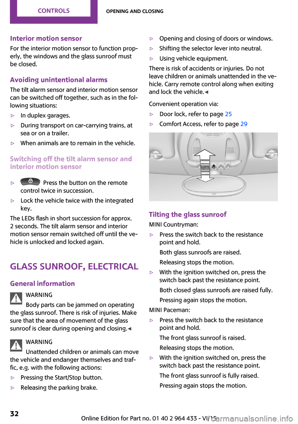
Tilting the glass sunroof
MINI Countryman:
▷Press the switch back to the resistance
point and hold.
Both glass sunroofs are raised.
Releasing stops the motion.▷With the ignition switched on, press the
switch back past the resistance point.
Both closed glass sunroofs are raised fully.
Pressing again stops the motion.
MINI Paceman:
▷Press the switch back to the resistance
point and hold.
The front glass sunroof is raised.
Releasing stops the motion.▷With the ignition switched on, press the
switch back past the resistance point.
The front glass sunroof is fully raised.
Pressing again stops the motion.Seite 32CONTROLSOpening and closing32
Online Edition for Part no. 01 40 2 964 433 - VI/15
Page 33 of 223
Opening, closingMINI Countryman:▷In the raised position with the ignition
switched on, press the switch back and
hold.
The front glass sunroof is opened. The rear
glass sunroof is closed.
Releasing stops the motion.
The same method is used to close the glass
sunroof, in this case by pressing the switch for‐
ward.
The front glass sunroof remains in the raised
position. The rear glass sunroof is raised. Press‐
ing again closes both sunroofs completely.
MINI Paceman:
▷In the raised position with the ignition
switched on, press the switch back and
hold.
The front glass sunroof is opened.
Releasing stops the motion.
The same method is used to close the glass
sunroof, in this case by pressing the switch for‐
ward.
The front glass sunroof remains in the raised
position. Pressing again closes the roof com‐
pletely.
Roller sunblind The roller sunblind can be opened and closed
separately from the glass sunroof.
After a power failure After a power failure, it could happen that the
sunroof can only be raised. In this case, have
the system initialized. The manufacturer of your
MINI recommends that this work be performed
by a dealer’s service center or another qualified
service center or repair shop.
Power windows
General information WARNING
When operating the windows, body parts
and objects can be jammed. There is risk of in‐
juries or risk of property damage. Make sure
that the area of movement of the windows is
clear during opening and closing. ◀
WARNING
Unattended children or animals can move
the vehicle and endanger themselves and traf‐
fic, e.g. with the following actions:▷Pressing the Start/Stop button.▷Releasing the parking brake.▷Opening and closing of doors or windows.▷Shifting the selector lever into neutral.▷Using vehicle equipment.
There is risk of accidents or injuries. Do not
leave children or animals unattended in the ve‐
hicle. Carry remote control along when exiting
and lock the vehicle. ◀
If, after having been opened and closed a num‐
ber of times in close succession, a window can
only be closed, the system is overheated. Let
the system cool down for several minutes with
the ignition switched on or the engine running.
Opening, closing
Front windows
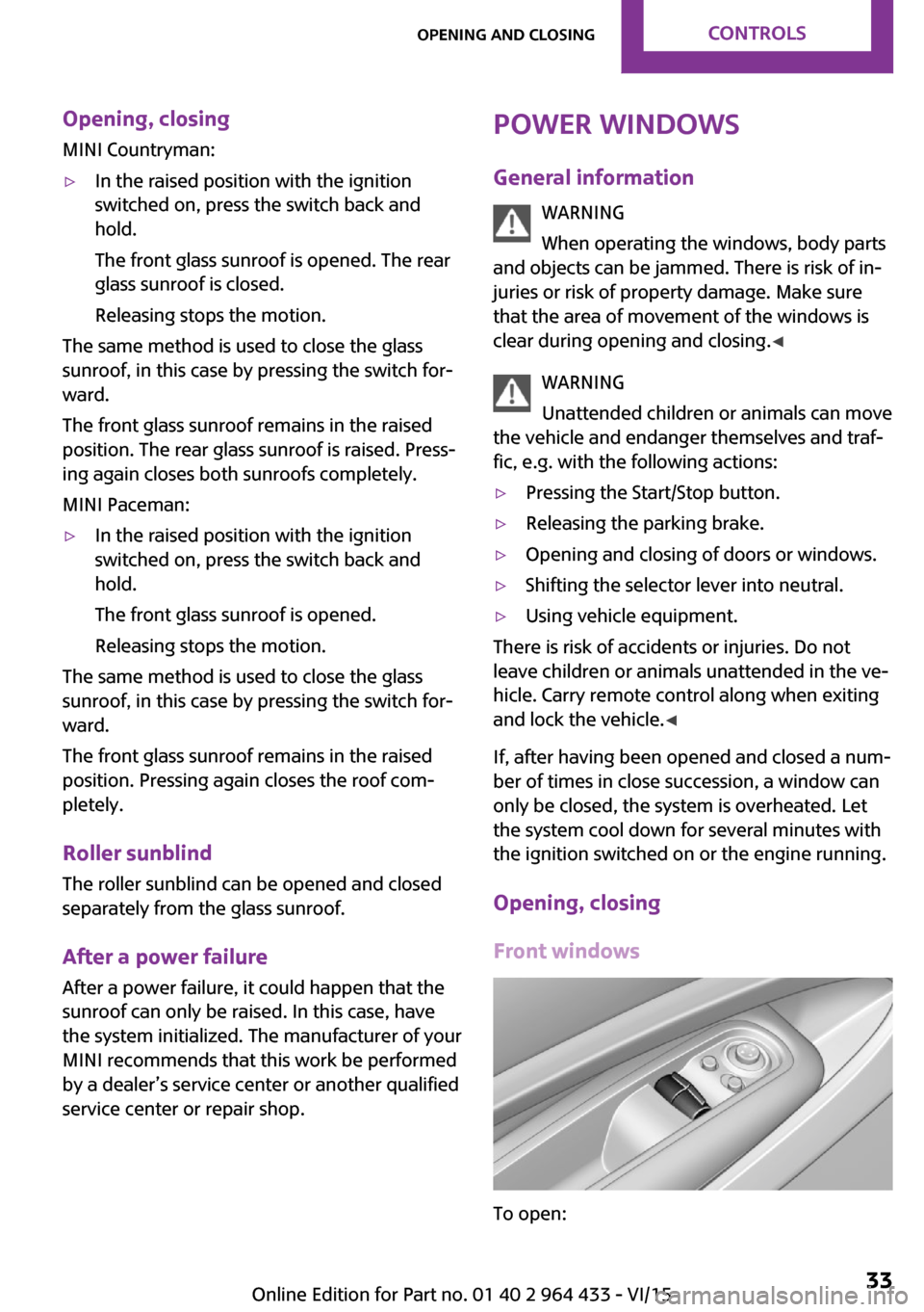
To open:
Seite 33Opening and closingCONTROLS33
Online Edition for Part no. 01 40 2 964 433 - VI/15
Page 45 of 223

Transporting children safelyVehicle features and op‐
tions
This chapter describes all standard, country-
specific and optional features offered with the
series. It also describes features that are not
necessarily available in your car, e. g., due to
the selected options or country versions. This
also applies to safety-related functions and sys‐
tems.
When using the features and systems described
here, adhere to local regulations.
The right place for chil‐
dren
Information WARNING
Unattended children or animals can move
the vehicle and endanger themselves and traf‐
fic, e.g. with the following actions:▷Pressing the Start/Stop button.▷Releasing the parking brake.▷Opening and closing of doors or windows.▷Shifting the selector lever into neutral.▷Using vehicle equipment.
There is risk of accidents or injuries. Do not
leave children or animals unattended in the ve‐
hicle. Carry remote control along when exiting
and lock the vehicle. ◀
Children should always be in the rear WARNING
Persons shorter than 5 ft, 150 cm cannot
correctly fasten the safety belt without suitable
additional restraint systems. The protective ef‐
fect of the safety belts can be limited or lost
when safety belts are fastened incorrectly. An
incorrectly fastened safety belt can cause addi‐
tional injuries, e.g. in the event of an accident
or during braking and evasive maneuvers.
There is risk of injuries or danger to life. Secure
persons shorter than 5 ft, 150 cm using suitable
restraint systems. ◀
Accident research shows that the safest place
for children is on the rear seat.
Only transport children younger than 12 years
of age (13 years of age) or shorter than 5 ft,
150 cm in the rear in child restraint systems
suitable for the age, weight and size of the
child.
Children 13 years of age or older must wear a
safety belt as soon as a suitable child restraint
system can no longer be used due to their age,
weight and size.
Children on the front passenger seat
Should it be necessary to use a child restraint
fixing system on the front passenger seat,
make sure that the front and side airbags on
the front passenger side are deactivated, refer
to page 75.
Information WARNING
Active front-seat passenger airbags can
injure a child in a child restraint system when
the airbags are activated. There is risk of inju‐
ries. Make sure that the front-seat passenger
airbags are deactivated and that the PASSEN‐
GER AIRBAG OFF indicator lamp lights up. ◀
WARNING
The stability of the child restraint system
is limited or compromised with incorrect seat
adjustment or improper installation of the child
seat. There is risk of injuries or danger to life.
Make sure that the child restraint system fitsSeite 45Transporting children safelyCONTROLS45
Online Edition for Part no. 01 40 2 964 433 - VI/15
Page 51 of 223
To save battery power when the engine is off,
switch off the ignition and any unnecessary
electronic systems/power consumers.
Radio ready state and ignition off All indicator and warning lights in the displays
go out.
The ignition switches off automatically when
the driver's door is opened. Pressing the Start/
Stop button again switches the ignition back
on.
For example, the ignition is not switched off in
the following situations:▷Depress the clutch or brake pedal.▷The low beams are switched on.
Starting the engine
General information DANGER
If the exhaust pipe is blocked or ventila‐
tion is insufficient, harmful exhaust gases can
enter into the vehicle. The exhaust gases con‐
tain carbon monoxide, an odorless and color‐
less but highly toxic gas. In enclosed areas, ex‐
haust gases can also accumulate outside of the
vehicle. There is danger to life. Keep the ex‐
haust pipe free and ensure sufficient ventila‐
tion. ◀
WARNING
An unsecured vehicle can put itself into
motion and roll away. There is risk of an acci‐
dent. Before exiting, secure the vehicle against
rolling.
In order to ensure that the vehicle is secured
against rolling away, observe the following:
▷Set the parking brake.▷On uphill grades or on a slope, turn the
front wheels in the direction of the curb.▷On uphill grades or on a slope, additionally
secure the vehicle, e.g. with a wheel
chock. ◀
CAUTION
In the case of repeated starting attempts
or repeated starting in quick succession, the
fuel is not burned or is inadequately burned.
The catalytic converter can overheat. There is
risk of property damage. Avoid repeated start‐
ing in quick succession. ◀
Do not wait for the engine to warm-up while
the vehicle remains stationary; start driving
right away, but at moderate engine speeds.
Do not depress the accelerator when starting
the engine.
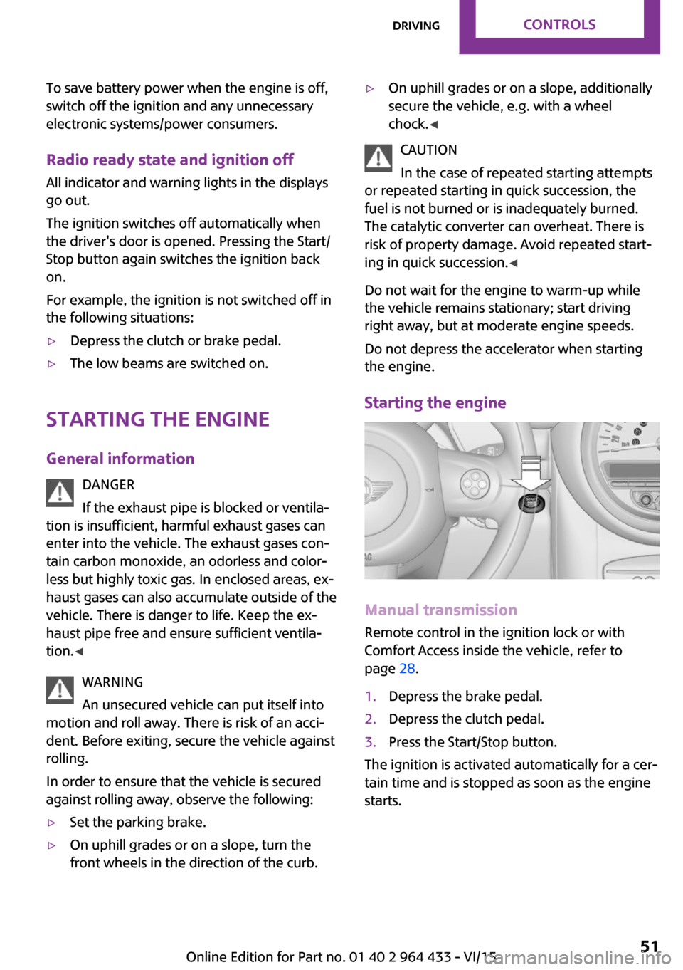
Starting the engine
Manual transmission
Remote control in the ignition lock or with
Comfort Access inside the vehicle, refer to
page 28.
1.Depress the brake pedal.2.Depress the clutch pedal.3.Press the Start/Stop button.
The ignition is activated automatically for a cer‐
tain time and is stopped as soon as the engine
starts.
Seite 51DrivingCONTROLS51
Online Edition for Part no. 01 40 2 964 433 - VI/15
Page 52 of 223

Steptronic transmissionRemote control in the ignition lock or, with
Comfort Access, inside the vehicle, refer to
page 28.1.Depress the brake pedal.2.Move the selector lever to position P or N.3.Press the Start/Stop button.
The ignition is activated automatically for a cer‐
tain time and is stopped as soon as the engine
starts.
Engine stop
General information WARNING
Unattended children or animals can move
the vehicle and endanger themselves and traf‐
fic, e.g. with the following actions:
▷Pressing the Start/Stop button.▷Releasing the parking brake.▷Opening and closing of doors or windows.▷Shifting the selector lever into neutral.▷Using vehicle equipment.
There is risk of accidents or injuries. Do not
leave children or animals unattended in the ve‐
hicle. Carry remote control along when exiting
and lock the vehicle. ◀
WARNING
An unsecured vehicle can put itself into
motion and roll away. There is risk of an acci‐
dent. Before exiting, secure the vehicle against
rolling.
In order to ensure that the vehicle is secured
against rolling away, observe the following:
▷Set the parking brake.▷On uphill grades or on a slope, turn the
front wheels in the direction of the curb.▷On uphill grades or on a slope, additionally
secure the vehicle, e.g. with a wheel
chock. ◀
Before driving into a car wash
To make it possible for the vehicle to roll in an
automatic car wash, follow the information on
Washing in automatic car washes, refer to
page 190.
Switching off the engine
Manual transmission
1.With the vehicle at a standstill, press the
Start/Stop button.2.Shift into first gear or reverse.3.Set the parking brake firmly.4.Remove the remote control from the igni‐
tion lock.
Steptronic transmission
1.Engage transmission position P with the ve‐
hicle stopped.2.Press the Start/Stop button.3.Set the parking brake firmly.4.Remove the remote control from the igni‐
tion lock.
Parking brake
The concept
The parking brake is primarily intended to pre‐
vent the vehicle from rolling while parked; it
brakes the rear wheels.
Also follow the instructions under Switching off
the engine, refer to page 52.
Setting The lever engages automatically.
Seite 52CONTROLSDriving52
Online Edition for Part no. 01 40 2 964 433 - VI/15
Page 53 of 223

Releasing
Pull up slightly, press the button, and lower the
lever.
Information If for once use during driving is required, en‐
gage the parking brake slightly and hold the
button down.
The brake lights do not light up when the park‐
ing brake is pulled.
Turn signal, high-beams,
headlight flasher
1Turn signal2Switching on the high-beams3Switching off the high-beams/headlight
flasher
Turn signal
Press the lever beyond the resistance point.
To switch off manually, press the lever to the
resistance point.
Unusually rapid flashing of the indicator lamp
indicates that a turn signal bulb has failed.
Signaling a turn briefly Press the lever to the resistance point and hold
it there for as long as you want the turn signal
to flash.
Triple turn signal activation Press the lever to the resistance point.
The turn signal flashes three times.
This function can be activated or deactivated:1.Switch on the ignition, refer to page 50.2.Press the button on the turn indicator lever
repeatedly until "SET/INFO" is displayed.3.Press and hold the button until the display
changes.4.Press the button repeatedly until the sym‐
bol and "SET" are displayed.5.Press and hold the button until the display
changes.Seite 53DrivingCONTROLS53
Online Edition for Part no. 01 40 2 964 433 - VI/15
Page 60 of 223

WARNING
If the transmission lock is released man‐
ually, the vehicle may begin to roll. There is risk
of an accident. Before manually unlocking the
transmission lock, set the parking brake to pre‐
vent the vehicle from rolling away. ◀Seite 60CONTROLSDriving60
Online Edition for Part no. 01 40 2 964 433 - VI/15
Page 86 of 223
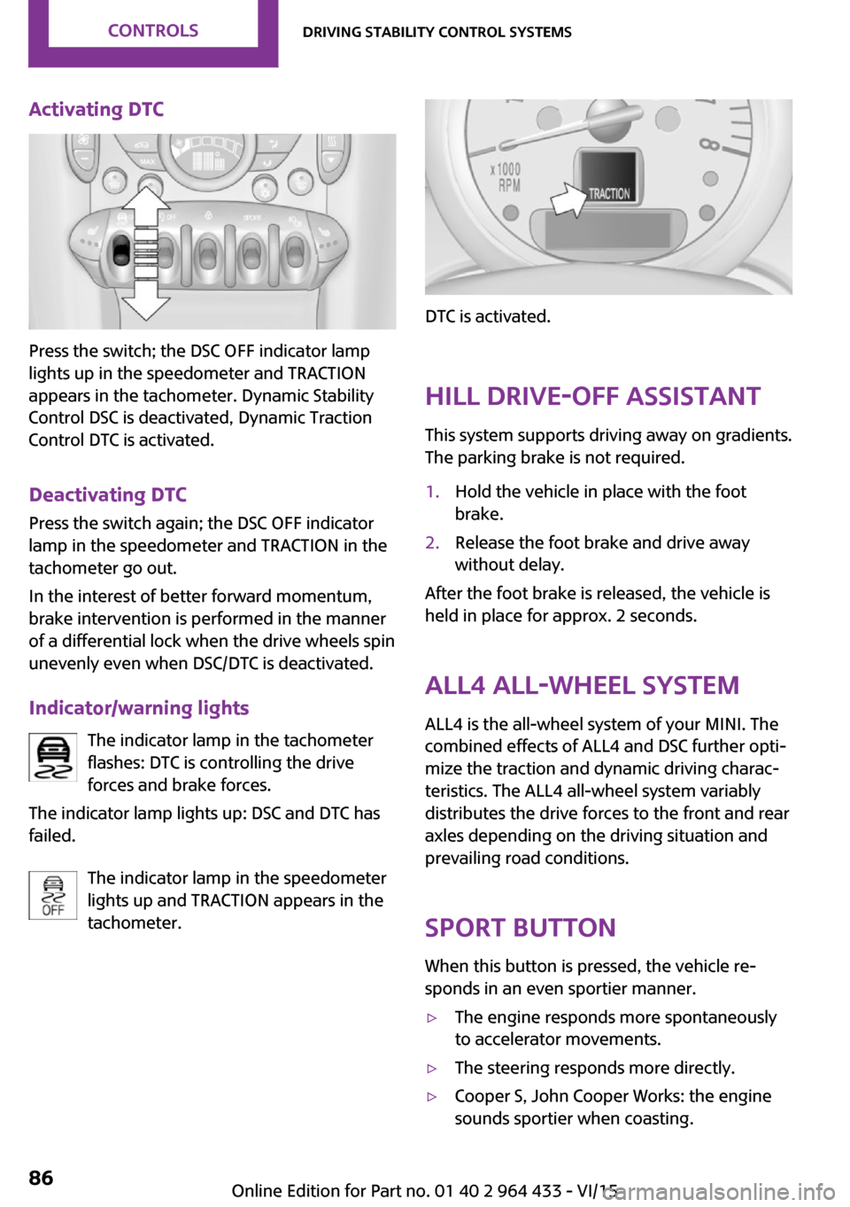
Activating DTC
Press the switch; the DSC OFF indicator lamp
lights up in the speedometer and TRACTION
appears in the tachometer. Dynamic Stability
Control DSC is deactivated, Dynamic Traction
Control DTC is activated.
Deactivating DTC Press the switch again; the DSC OFF indicator
lamp in the speedometer and TRACTION in the
tachometer go out.
In the interest of better forward momentum,
brake intervention is performed in the manner
of a differential lock when the drive wheels spin
unevenly even when DSC/DTC is deactivated.
Indicator/warning lights The indicator lamp in the tachometer
flashes: DTC is controlling the drive
forces and brake forces.
The indicator lamp lights up: DSC and DTC has
failed.
The indicator lamp in the speedometer
lights up and TRACTION appears in the
tachometer.
DTC is activated.
Hill drive-off assistant This system supports driving away on gradients.
The parking brake is not required.
1.Hold the vehicle in place with the foot
brake.2.Release the foot brake and drive away
without delay.
After the foot brake is released, the vehicle is
held in place for approx. 2 seconds.
ALL4 all-wheel system ALL4 is the all-wheel system of your MINI. The
combined effects of ALL4 and DSC further opti‐
mize the traction and dynamic driving charac‐
teristics. The ALL4 all-wheel system variably
distributes the drive forces to the front and rear
axles depending on the driving situation and
prevailing road conditions.
Sport button When this button is pressed, the vehicle re‐
sponds in an even sportier manner.
▷The engine responds more spontaneously
to accelerator movements.▷The steering responds more directly.▷Cooper S, John Cooper Works: the engine
sounds sportier when coasting.Seite 86CONTROLSDriving stability control systems86
Online Edition for Part no. 01 40 2 964 433 - VI/15
Page 112 of 223
Things to remember when drivingVehicle features and op‐tions
This chapter describes all standard, country-
specific and optional features offered with the
series. It also describes features that are not
necessarily available in your car, e. g., due to
the selected options or country versions. This
also applies to safety-related functions and sys‐
tems.
When using the features and systems described
here, adhere to local regulations.
Breaking-in period
General information Moving parts need to be broken in to adjust to
each other.
The following instructions will help achieve a
long vehicle life and good economy.
Engine and differential
Always obey all official speed limits.
Up to 1,200 miles/2,000 kmDrive at various engine and vehicle speeds, but
do not exceed:▷For a gasoline engine, 4,500 rpm and
100 mph/160 km/h.
Avoid full-throttle operation and use of the
transmission's kickdown mode for the initial
miles.
From 1,200 miles/2,000 km
The engine and vehicle speed can gradually be
increased.
Tires
Due to technical factors associated with their
manufacture, tires do not achieve their full trac‐
tion potential until after an initial breaking-in
period.
Drive conservatively for the first
200 miles/300 km.
Brake system Brakes require an initial break-in period of ap‐
prox. 300 miles/500 km to achieve optimized
contact and wear patterns between brake pads
and discs. Drive cautiously during this break-in
period.
Clutch
The clutch requires an initial break-in period of
approx. 300 miles/500 km to function at an op‐
timal level.
During this break-in period, engage the clutch
gently.
Following part replacement
The same breaking in procedures should be ob‐
served if any of the components mentioned
above have to be renewed in the course of the
vehicle's operating life.
General driving notes
Ground clearance CAUTION
If ground clearance is insufficient, there
might be contact with the front or rear spoiler
e.g. when driving over curbs or entering into
underground car parking garages. There is risk
of property damage. Ensure that there is suffi‐
cient ground clearance available. ◀Seite 112DRIVING TIPSThings to remember when driving112
Online Edition for Part no. 01 40 2 964 433 - VI/15
Page 113 of 223
Closing the tailgateWARNING
An open tailgate protrudes from the vehi‐
cle and can endanger occupants and other traf‐
fic participants or damage the vehicle in the
event of an accident, braking or evasive ma‐
neuvers. In addition, exhaust fumes may enter
the vehicle interior. There is risk of injuries or
risk of property damage. Do not drive with the
tailgate open. ◀
If, despite this, the vehicle must be driven with
the tailgate open:▷Drive moderately.▷Close all windows and the glass sunroof.▷Switch off recirculated air mode and greatly
increase the blower speed.
Hot exhaust system
WARNING
During driving operation, high tempera‐
tures can occur underneath the body, e.g.
caused by the exhaust gas system. If combusti‐
ble materials, such as leaves or grass, come in
contact with hot parts of the exhaust gas sys‐
tem, these materials can ignite. There is risk of
injuries or risk of property damage.
Do not remove the heat shields installed and
never apply undercoating to them. Make sure
that no combustible materials can come in con‐
tact with hot vehicle parts in driving operation,
idle or during parking. Do not touch the hot ex‐
haust system. ◀
Mobile communication devices in the vehicle
WARNING
The vehicle's performance may be af‐
fected by interference from high frequency
radio signals. These signals are emitted by a
series of transmission systems, such as from air
traffic beacons or relay stations for mobile tele‐
communications.
If you have problems of this nature, we recom‐
mend that you consult your dealer’s service
center or another qualified service center or re‐
pair shop. ◀
Hydroplaning On wet or slushy roads, a wedge of water can
form between the tires and road surface.
This phenomenon is referred to as hydroplan‐
ing. It is characterized by a partial or complete
loss of contact between the tires and the road
surface, ultimately undermining your ability to
steer and brake the vehicle.
The risk of hydroplaning increases as the tire
tread depth decreases. Minimum tread depth,
refer to page 160.
Driving through water Drive though calm water only if it is not deeper
than 12 inches/30 cm and at this height, no
faster than walking speed, up to
6 mph/10 km/h.
Using the parking brake on inclines On inclines, do not hold the vehicle stationary
with a slipping clutch for extended period; use
the parking brake instead. Otherwise, the
clutch will be subject to increased wear.
Support from the hill drive-off assistant, refer to
page 86.
Braking safely The vehicle is equipped with ABS as a standardfeature.
Applying the brakes fully is the most effective
way of braking in situations when this is neces‐
sary.
The vehicle maintains steering responsiveness.
You can still avoid any obstacles with a mini‐
mum of steering effort.
Pulsation of the brake pedal and sounds from
the hydraulic circuits indicate that ABS is in its
active mode.Seite 113Things to remember when drivingDRIVING TIPS113
Online Edition for Part no. 01 40 2 964 433 - VI/15