ECU MINI Paceman 2016 Owner's Guide
[x] Cancel search | Manufacturer: MINI, Model Year: 2016, Model line: Paceman, Model: MINI Paceman 2016Pages: 223, PDF Size: 5.52 MB
Page 116 of 223
LoadingVehicle features and op‐tions
This chapter describes all standard, country-
specific and optional features offered with the
series. It also describes features that are not
necessarily available in your car, e. g., due to
the selected options or country versions. This
also applies to safety-related functions and sys‐
tems.
When using the features and systems described
here, adhere to local regulations.
General information WARNING
High gross weight can overheat the tires,
damage them internally, and cause a sudden drop in tire inflation pressure. There is risk of an
accident. Pay attention to the permitted load
capacity of the tires and never exceed the per‐
mitted gross weight. ◀
CAUTION
Fluids in the cargo area can cause dam‐
age. There is risk of property damage. Make sure that no fluids leak in the cargo area. ◀
WARNING Loose objects in the car's interior can be
thrown into the car's interior while driving, e.g.
in the event of an accident or during braking
and evasive maneuvers. There is risk of injuries.
Secure loose objects in the car's interior. ◀Determining the load
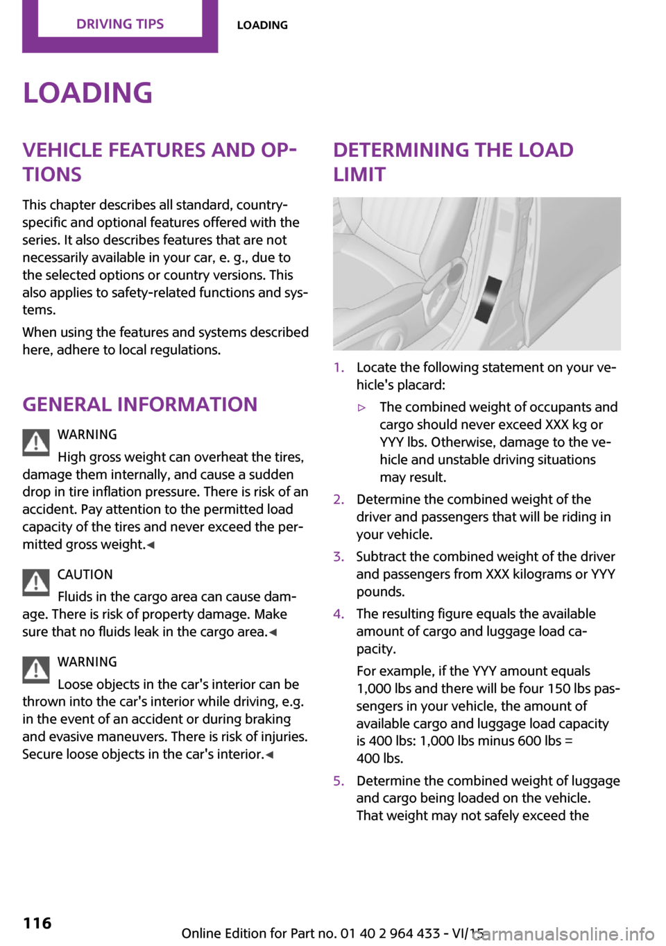
limit1.Locate the following statement on your ve‐
hicle's placard:▷The combined weight of occupants and
cargo should never exceed XXX kg or
YYY lbs. Otherwise, damage to the ve‐
hicle and unstable driving situations
may result.2.Determine the combined weight of the
driver and passengers that will be riding in
your vehicle.3.Subtract the combined weight of the driver
and passengers from XXX kilograms or YYY
pounds.4.The resulting figure equals the available
amount of cargo and luggage load ca‐
pacity.
For example, if the YYY amount equals
1,000 lbs and there will be four 150 lbs pas‐
sengers in your vehicle, the amount of
available cargo and luggage load capacity
is 400 lbs: 1,000 lbs minus 600 lbs =
400 lbs.5.Determine the combined weight of luggage
and cargo being loaded on the vehicle.
That weight may not safely exceed theSeite 116DRIVING TIPSLoading116
Online Edition for Part no. 01 40 2 964 433 - VI/15
Page 117 of 223
available cargo and luggage load capacity
calculated in Step 4.6.If your vehicle will be towing a trailer, load
from your trailer will be transfered to your
vehicle. Consult the manual for transporting
a trailer to determine how this may reduce
the available cargo and luggage load ca‐
pacity of your vehicle.
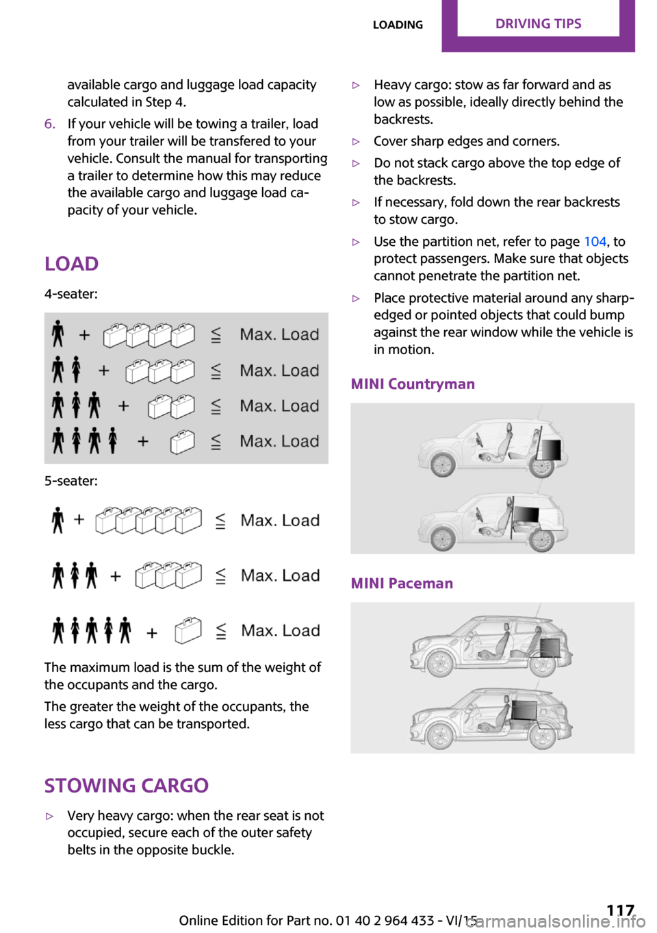
Load
4-seater:
5-seater:
The maximum load is the sum of the weight of
the occupants and the cargo.
The greater the weight of the occupants, the
less cargo that can be transported.
Stowing cargo
▷Very heavy cargo: when the rear seat is not
occupied, secure each of the outer safety
belts in the opposite buckle.▷Heavy cargo: stow as far forward and as
low as possible, ideally directly behind the
backrests.▷Cover sharp edges and corners.▷Do not stack cargo above the top edge of
the backrests.▷If necessary, fold down the rear backrests
to stow cargo.▷Use the partition net, refer to page 104, to
protect passengers. Make sure that objects
cannot penetrate the partition net.▷Place protective material around any sharp-
edged or pointed objects that could bump
against the rear window while the vehicle is
in motion.
MINI Countryman
MINI Paceman
Seite 117LoadingDRIVING TIPS117
Online Edition for Part no. 01 40 2 964 433 - VI/15
Page 118 of 223
Securing cargoLashing eyes in the cargo area
MINI Countryman
MINI Paceman
Securing cargo
▷Secure smaller and lighter pieces with tight‐
ening belts or straps.▷Secure larger and heavier pieces with cargo
straps.
Adhere to the information included with
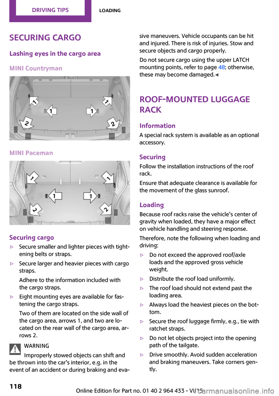
the cargo straps.▷Eight mounting eyes are available for fas‐
tening the cargo straps.
Two of them are located on the side wall of
the cargo area, arrows 1, and two are lo‐
cated on the rear wall of the cargo area, ar‐
rows 2.
WARNING
Improperly stowed objects can shift and
be thrown into the car's interior, e.g. in the
event of an accident or during braking and eva‐
sive maneuvers. Vehicle occupants can be hit
and injured. There is risk of injuries. Stow and
secure objects and cargo properly.
Do not secure cargo using the upper LATCH
mounting points, refer to page 48; otherwise,
these may become damaged. ◀
Roof-mounted luggage
rack
InformationA special rack system is available as an optional
accessory.
Securing
Follow the installation instructions of the roof
rack.
Ensure that adequate clearance is available for
the movement of the glass sunroof.
Loading Because roof racks raise the vehicle's center ofgravity when loaded, they have a major effect
on vehicle handling and steering response.
Therefore, note the following when loading and driving:▷Do not exceed the approved roof/axle
loads and the approved gross vehicle
weight.▷Distribute the roof load uniformly.▷The roof load should not extend past the
loading area.▷Always load the heaviest pieces on the bot‐
tom.▷Secure the roof luggage firmly, e.g., tie with
ratchet straps.▷Do not let objects project into the opening
path of the tailgate.▷Drive smoothly. Avoid sudden acceleration
and braking maneuvers. Take corners gen‐
tly.Seite 118DRIVING TIPSLoading118
Online Edition for Part no. 01 40 2 964 433 - VI/15
Page 138 of 223
TelephoneVehicle features and op‐
tions
This chapter describes all standard, country-
specific and optional features offered with the
series. It also describes features that are not
necessarily available in your car, e. g., due to
the selected options or country versions. This
also applies to safety-related functions and sys‐
tems.
When using the features and systems described
here, adhere to local regulations.
Overview
The concept
Mobile phones can be connected with the vehi‐
cle via Bluetooth.
After a compatible mobile phone is paired with
the vehicle once, you can operate the mobile phone via the radio, the buttons on the steer‐
ing wheel, and via voice activation.
Bluetooth® is a registered trademark of Blue‐
tooth® SIG, Inc.
Certain functions may need to be enabled by
the mobile phone provider or service provider.
WARNING
Operating the integrated information sys‐
tems and communication devices while driving can distract from traffic. It is possible to lose
control of the vehicle. There is risk of an acci‐
dent. Only use the systems or devices when the
traffic situation allows. If necessary stop and
use the systems and devices while the vehicle is
stationary. ◀
Snap-in adapter
The snap-in adapter is used to:▷Hold the mobile phone.▷Recharge the battery.▷Connect the mobile phone to an outside
antenna of the vehicle.
This provides for better network reception
and consistent sound quality.
Do not operate a mobile phone that is con‐
nected to the vehicle on the mobile phone key‐
pad, as this may lead to a malfunction.
Compatible mobile phones
Details on which mobile phones with a Blue‐
tooth interface are supported by the mobile
phone preparation package can be obtained at
www.mini.com/connectivity.
InformationAt high temperatures, the charging function of
the mobile phone may be limited and functions
may not be executed.
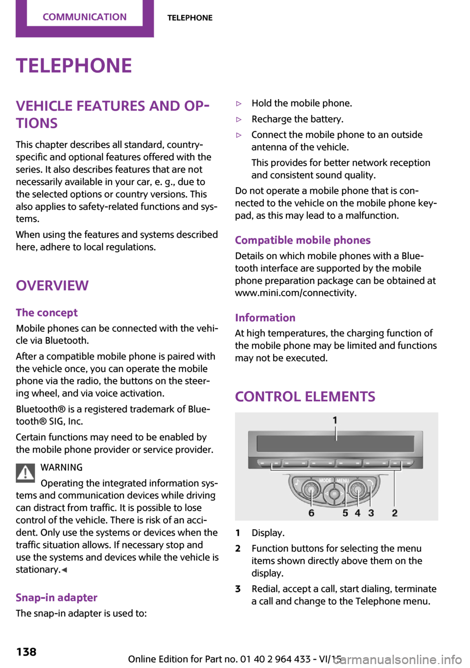
Control elements
1Display.2Function buttons for selecting the menu
items shown directly above them on the
display.3Redial, accept a call, start dialing, terminate
a call and change to the Telephone menu.Seite 138COMMUNICATIONTelephone138
Online Edition for Part no. 01 40 2 964 433 - VI/15
Page 145 of 223

▷"Road Assist": Roadside Assistance, if help
is required in the event of a breakdown.▷"Serv. Appt.": MINI service center, if a serv‐
ice appointment needs to be arranged.▷"Cust Relat": Customer Relations, for infor‐
mation on all aspects of your vehicle.
Displaying the phone numbers
1.Switch on the radio ready state or the igni‐
tion.2. Press the button.3."MINI"4.Turn the right knob until the desired phone
number is displayed.
Snap-in adapter
General information For more information about snap-in adapters
that support the functions of the mobile phone
in a compatible way, contact a dealer's service
center or another qualified service center or re‐
pair shop.
Information At high temperatures, the charging function of
the mobile phone may be limited and functions
may not be executed.
When using the mobile phone via the vehicle,
note the operating instructions of the mobile
phone.
Installation position
In the center armrest.
Inserting/removing the snap-in adapter1.Press the button, arrow 1, and remove the
cover, arrow 2.2.Insert the snap-in adapter at the front, ar‐
row 1, and press down, arrow 2, until it en‐
gages.
To remove:
To remove the snap-in adapter, press the but‐
ton.
Inserting the mobile phone
1.Depending on the mobile phone, remove
the protective cap from the antenna con‐
nector and from the USB connection of the
mobile phone.2.With the buttons facing up, slide the mobile
phone up toward the electrical contacts, ar‐Seite 145TelephoneCOMMUNICATION145
Online Edition for Part no. 01 40 2 964 433 - VI/15
Page 167 of 223
Hood
Information WARNING
Improperly executed work in the engine
compartment can damage vehicle components
and impair vehicle functions. There is a risk of
personal and property damage. The manufac‐
turer of your vehicle recommends that, in the
effort to avoid such risks, work in the engine
compartment be performed by a dealer’s serv‐
ice center or another qualified service center or
repair shop. ◀
CAUTION
Folded-away wipers can be jammed
when the hood is opened. There is risk of prop‐
erty damage. Make sure that the wipers with
the wiper blades mounted are folded down onto the windshield before opening the
hood. ◀
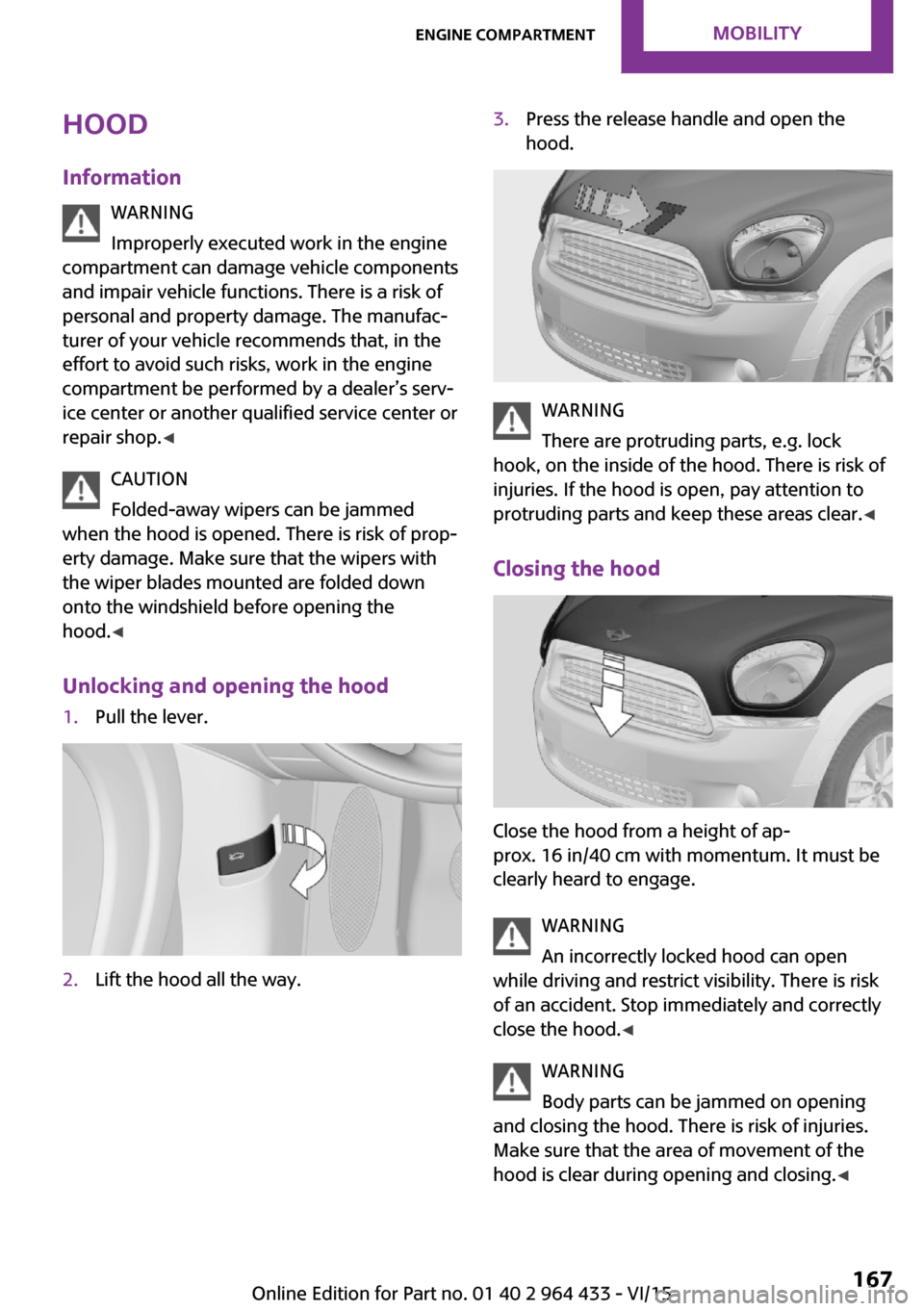
Unlocking and opening the hood1.Pull the lever.2.Lift the hood all the way.3.Press the release handle and open the
hood.
WARNING
There are protruding parts, e.g. lock
hook, on the inside of the hood. There is risk of
injuries. If the hood is open, pay attention to
protruding parts and keep these areas clear. ◀
Closing the hood
Close the hood from a height of ap‐
prox. 16 in/40 cm with momentum. It must be
clearly heard to engage.
WARNING
An incorrectly locked hood can open
while driving and restrict visibility. There is risk
of an accident. Stop immediately and correctly
close the hood. ◀
WARNING
Body parts can be jammed on opening
and closing the hood. There is risk of injuries.
Make sure that the area of movement of the
hood is clear during opening and closing. ◀
Seite 167Engine compartmentMOBILITY167
Online Edition for Part no. 01 40 2 964 433 - VI/15
Page 174 of 223

Replacing componentsVehicle features and op‐
tions
This chapter describes all standard, country-
specific and optional features offered with the
series. It also describes features that are not
necessarily available in your car, e. g., due to
the selected options or country versions. This
also applies to safety-related functions and sys‐
tems.
When using the features and systems described
here, adhere to local regulations.
Wiper blade replacement
General information CAUTION
If the wiper arm falls onto the windshield
without the wiper blades installed, the wind‐
shield can be damaged. There is risk of prop‐
erty damage. Secure the wiper arm when re‐
placing the wiper blades and do not fold down
the wipers without the wiper blades installed. ◀
Replacing the front wiper blades1.Fold up and hold the wiper arm.2.Squeeze the locking spring, arrows 1, and
fold out the wiper blade, arrow 2.3.Take the wiper blade out of the catch
mechanism toward the front.4.Press the new wiper blade into the fixation
until it engages audibly.5.Fold down the wiper arm.
CAUTION
Folded-away wipers can be jammed
when the hood is opened. There is risk of prop‐
erty damage. Make sure that the wipers with
the wiper blades mounted are folded down
onto the windshield before opening the
hood. ◀
Changing the rear wiper blade
MINI Countryman:
MINI Paceman:
1.Fold up and hold the wiper arm.2.Turn the wiper blade all the way back, ar‐
row.Seite 174MOBILITYReplacing components174
Online Edition for Part no. 01 40 2 964 433 - VI/15
Page 183 of 223

Disposing of old batteriesAfter they are replaced, have old bat‐teries disposed of by a dealer’s service
center or another qualified service cen‐
ter or repair shop or take them to a collection
point.
Maintain the battery in an upright position for
transport and storage. Secure the battery so
that it does not tip over during transport.
Fuses WARNING
Incorrect and repaired fuses can overload
electrical lines and components. There is risk of
fire. Never attempt to repair a blown fuse and
do not replace a nonworking fuse with a substi‐ tute of another color or amperage rating. ◀
Have the fuses replaced by a dealer’s service
center or another qualified service center or re‐
pair shop.
Information on the fuses can be found on the
inside of the covers.
In the engine compartment
Opening the cover
Press the snap lock.
In interior
On the right side of the footwell.
Opening the cover
Push out at the recess.
Seite 183Replacing componentsMOBILITY183
Online Edition for Part no. 01 40 2 964 433 - VI/15
Page 193 of 223

Do not use abrasive cleaners or a steam jet hot‐
ter than 140 ℉/60 ℃; otherwise, damage may
result. Adhere to the manufacturer instructions.
Aggressive, acidic, or alkaline cleaners may de‐
stroy the protective coating of neighboring
components such as the brake disc.
Exterior sensors The sensors on the outside of the vehicle, such
as for Park Distance Control, must be kept clean
and free of ice to ensure that they remain fully
functional.
Decorative trim
Clean decorative trims and fine wood compo‐
nents with a moist cloth only. Then dry with a
soft cloth.
Safety belts Dirty belt straps impede the reeling action and
thus have a negative impact on safety.
WARNING
Chemical cleansers can destroy the safety
belt webbing. Missing protective effect of the
safety belts. There is risk of injuries or danger to
life. Use only a mild soapy solution for cleaning
the safety belts. ◀
Carpets/floor mats WARNING
Objects in the driver's floor area can limit
the pedal distance or block a depressed pedal.
There is risk of an accident. Stow objects in the
vehicle such that they are secured and cannot
enter into the driver's floor area. Use floor mats
that are suitable for the vehicle and can be
safely attached to the floor. Do not use loose
floor mats and do not layer several floor mats.
Make sure that there is sufficient clearance for
the pedals. Ensure that the floor mats are se‐
curely fastened again after they were removed,
e.g. for cleaning. ◀
Floor mats can be removed for cleaning.If they are very dirty, clean with a microfiber
cloth and water or an interior cleaner. To pre‐
vent matting of the carpet, rub back and forth
in the direction of travel only.
Displays
To clean the displays, such as the radio or dis‐
play elements, use an antistatic microfiber
cloth.
CAUTION
Chemical cleansers, moisture or fluids of
any kind can damage the surface of displays
and screens. There is risk of property damage.
Clean with a clean, antistatic microfiber cloth. ◀
CD/DVD drives CAUTION
The use of cleaning CDs may damage
parts of the drive. There is risk of property dam‐
age. Do not use cleaning CDs. ◀
Long-term vehicle storage
A dealer's service center or another qualified
service center or repair shop can advise you on
what to consider when storing the vehicle for
longer than three months.Seite 193CareMOBILITY193
Online Edition for Part no. 01 40 2 964 433 - VI/15
Page 197 of 223
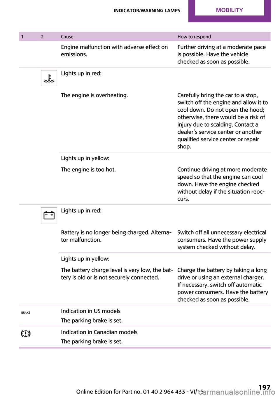
12CauseHow to respondEngine malfunction with adverse effect on
emissions.Further driving at a moderate pace
is possible. Have the vehicle
checked as soon as possible.Lights up in red:The engine is overheating.Carefully bring the car to a stop,
switch off the engine and allow it to
cool down. Do not open the hood;
otherwise, there would be a risk of
injury due to scalding. Contact a
dealer’s service center or another
qualified service center or repair
shop.Lights up in yellow:The engine is too hot.Continue driving at more moderate
speed so that the engine can cool
down. Have the engine checked
without delay if the situation reoc‐
curs.Lights up in red:Battery is no longer being charged. Alterna‐
tor malfunction.Switch off all unnecessary electrical
consumers. Have the power supply
system checked without delay.Lights up in yellow:The battery charge level is very low, the bat‐
tery is old or is not securely connected.Charge the battery by taking a long
drive or using an external charger.
If necessary, switch off automatic
power consumers. Have the battery
checked as soon as possible.Indication in US models
The parking brake is set.Indication in Canadian models
The parking brake is set.Seite 197Indicator/warning lampsMOBILITY197
Online Edition for Part no. 01 40 2 964 433 - VI/15