service indicator MINI Paceman 2016 Owner's Manual
[x] Cancel search | Manufacturer: MINI, Model Year: 2016, Model line: Paceman, Model: MINI Paceman 2016Pages: 223, PDF Size: 5.52 MB
Page 14 of 223
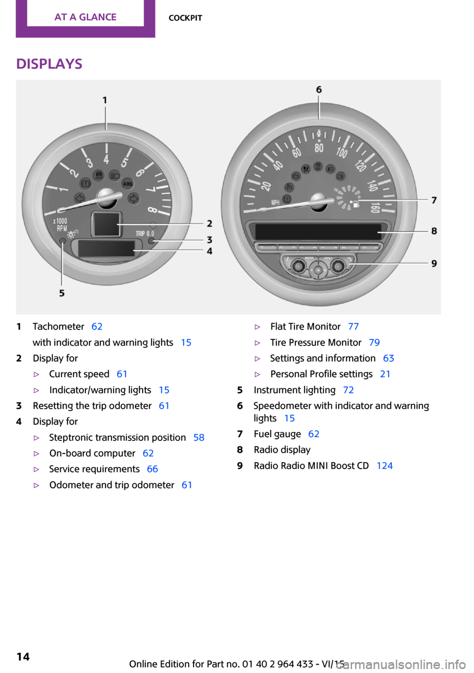
Displays1Tachometer 62
with indicator and warning lights 152Display for▷Current speed 61▷Indicator/warning lights 153Resetting the trip odometer 614Display for▷Steptronic transmission position 58▷On-board computer 62▷Service requirements 66▷Odometer and trip odometer 61▷Flat Tire Monitor 77▷Tire Pressure Monitor 79▷Settings and information 63▷Personal Profile settings 215Instrument lighting 726Speedometer with indicator and warning
lights 157Fuel gauge 628Radio display9Radio Radio MINI Boost CD 124Seite 14AT A GLANCECockpit14
Online Edition for Part no. 01 40 2 964 433 - VI/15
Page 30 of 223
control or when a mobile phone is being
charged in the vehicle.
If this occurs, open or close the vehicle using
the buttons on the remote control or use the
integrated key in the door lock.
To start the engine afterward, insert the remote
control into the ignition switch.
Warning lights The warning light in the instrument
cluster lights up when you attempt to
start the engine: the engine cannot be
started.
The remote control is not in the vehicle or has a
malfunction. Take the remote control with you
inside the vehicle or have it checked. If neces‐
sary, insert another remote control into the ig‐
nition switch.
The warning lamp in the instrument
cluster lights up while the engine is run‐
ning: the remote control is no longer in‐
side the vehicle.
After switching off the engine, the engine can
only be started again within approx. 10 sec‐
onds if no door has been opened.
The indicator lamp lights up: replace
the remote control battery.Replacing the battery
The remote control for Comfort Access contains
a battery that will need to be replaced from
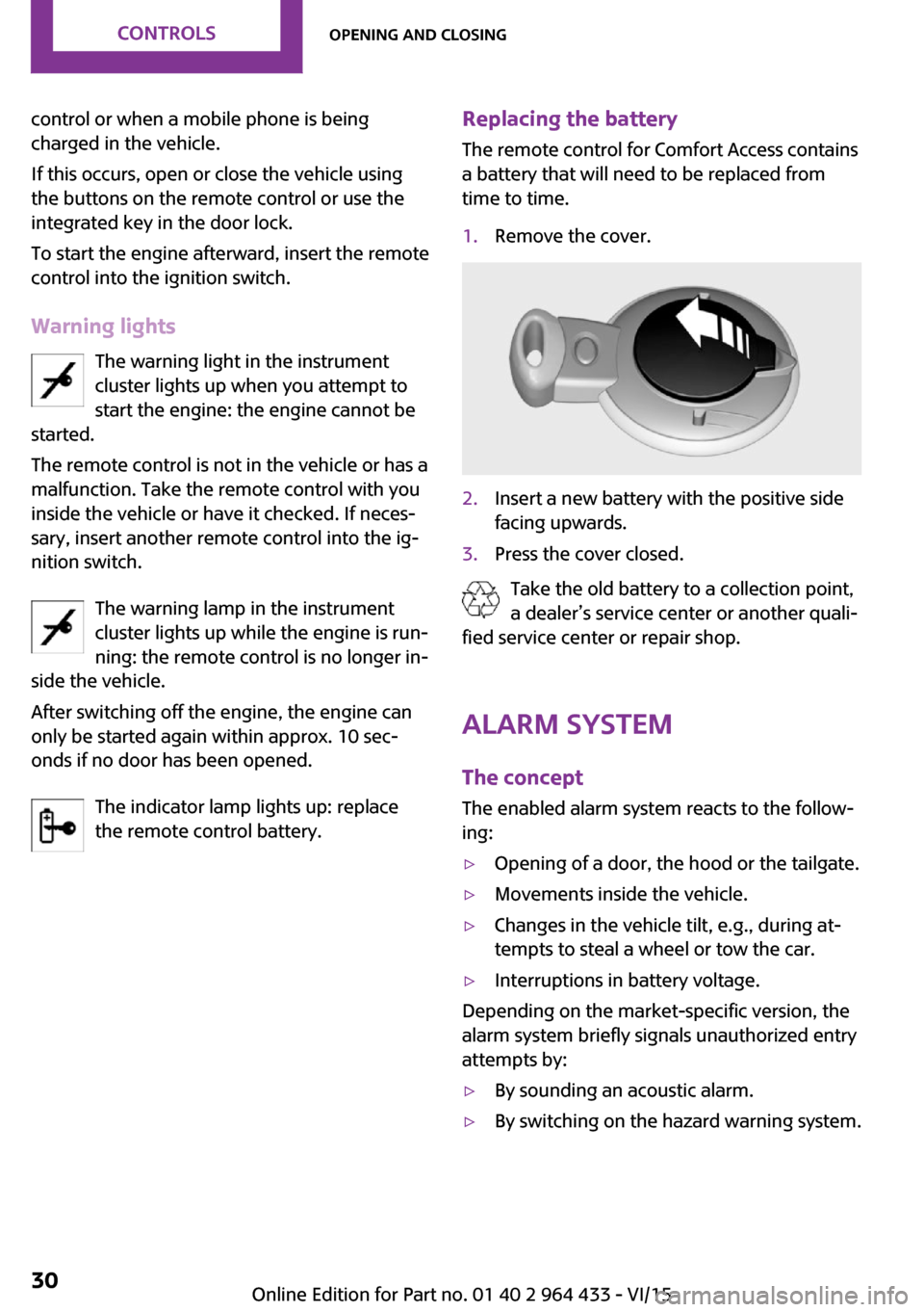
time to time.1.Remove the cover.2.Insert a new battery with the positive side
facing upwards.3.Press the cover closed.
Take the old battery to a collection point,
a dealer’s service center or another quali‐
fied service center or repair shop.
Alarm system
The concept
The enabled alarm system reacts to the follow‐
ing:
▷Opening of a door, the hood or the tailgate.▷Movements inside the vehicle.▷Changes in the vehicle tilt, e.g., during at‐
tempts to steal a wheel or tow the car.▷Interruptions in battery voltage.
Depending on the market-specific version, the
alarm system briefly signals unauthorized entry
attempts by:
▷By sounding an acoustic alarm.▷By switching on the hazard warning system.Seite 30CONTROLSOpening and closing30
Online Edition for Part no. 01 40 2 964 433 - VI/15
Page 41 of 223
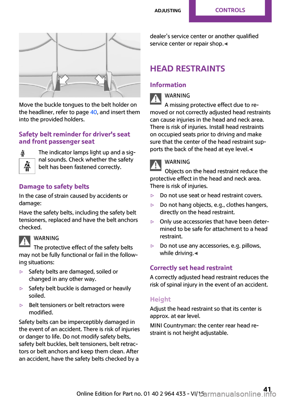
Move the buckle tongues to the belt holder on
the headliner, refer to page 40, and insert them
into the provided holders.
Safety belt reminder for driver's seat
and front passenger seat
The indicator lamps light up and a sig‐
nal sounds. Check whether the safety
belt has been fastened correctly.
Damage to safety belts
In the case of strain caused by accidents or
damage:
Have the safety belts, including the safety belt
tensioners, replaced and have the belt anchors
checked.
WARNING
The protective effect of the safety belts
may not be fully functional or fail in the follow‐
ing situations:
▷Safety belts are damaged, soiled or
changed in any other way.▷Safety belt buckle is damaged or heavily
soiled.▷Belt tensioners or belt retractors were
modified.
Safety belts can be imperceptibly damaged in
the event of an accident. There is risk of injuries
or danger to life. Do not modify safety belts,
safety belt buckles, belt tensioners, belt retrac‐
tors or belt anchors and keep them clean. After
an accident, have the safety belts checked by a
dealer’s service center or another qualified
service center or repair shop. ◀
Head restraints
Information WARNING
A missing protective effect due to re‐
moved or not correctly adjusted head restraints
can cause injuries in the head and neck area.
There is risk of injuries. Install head restraints
on occupied seats prior to driving and make sure that the center of the head restraint sup‐
ports the back of the head at eye level. ◀
WARNING
Objects on the head restraint reduce the
protective effect in the head and neck area.
There is risk of injuries.▷Do not use seat or head restraint covers.▷Do not hang objects, e.g., clothes hangers,
directly on the head restraint.▷Only use accessories that have been deter‐
mined to be safe for attachment to a head
restraint.▷Do not use any accessories, e.g. pillows,
while driving. ◀
Correctly set head restraint
A correctly adjusted head restraint reduces the
risk of spinal injury in the event of an accident.
Height Adjust the head restraint so that its center is
approx. at ear level.
MINI Countryman: the center rear head re‐
straint is not height adjustable.
Seite 41AdjustingCONTROLS41
Online Edition for Part no. 01 40 2 964 433 - VI/15
Page 63 of 223
Information in detail
Range
Displays the estimated cruising range available
with the remaining fuel.
It is calculated based on your driving style over
the last 18 miles/30 km.
Average fuel consumption This is calculated for the period during which
the engine is running.
To reset the average consumption: press the
button on the turn indicator lever for ap‐
prox. 2 seconds.
Current fuel consumption Displays the current fuel consumption. You can
check whether you are currently driving in an
efficient and environmentally-friendly manner.
Average speed Periods in which the vehicle was parked and
the engine was switched off manually are not
included in the average speed calculations.
To reset the average speed: press the button
on the turn indicator lever for approx. 2 sec‐
onds.
Radio MINI Boost CD: displays on the
radio
Some computer functions can also be shown
on the radio display, refer to page 127.
Settings and information Operating conceptSome settings and information can only be cre‐
ated or opened while the ignition is switched
on, the vehicle is standing, and the doors are
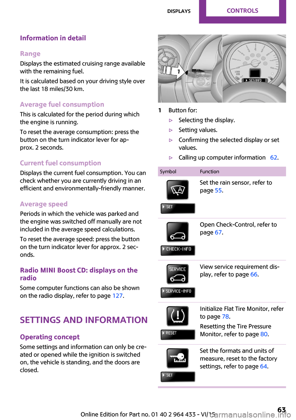
closed.1Button for:▷Selecting the display.▷Setting values.▷Confirming the selected display or set
values.▷Calling up computer information 62.SymbolFunctionSet the rain sensor, refer to
page 55.Open Check-Control, refer to
page 67.View service requirement dis‐
play, refer to page 66.Initialize Flat Tire Monitor, refer
to page 78.
Resetting the Tire Pressure
Monitor, refer to page 80.Set the formats and units of
measure, reset to the factory
settings, refer to page 64.Seite 63DisplaysCONTROLS63
Online Edition for Part no. 01 40 2 964 433 - VI/15
Page 66 of 223
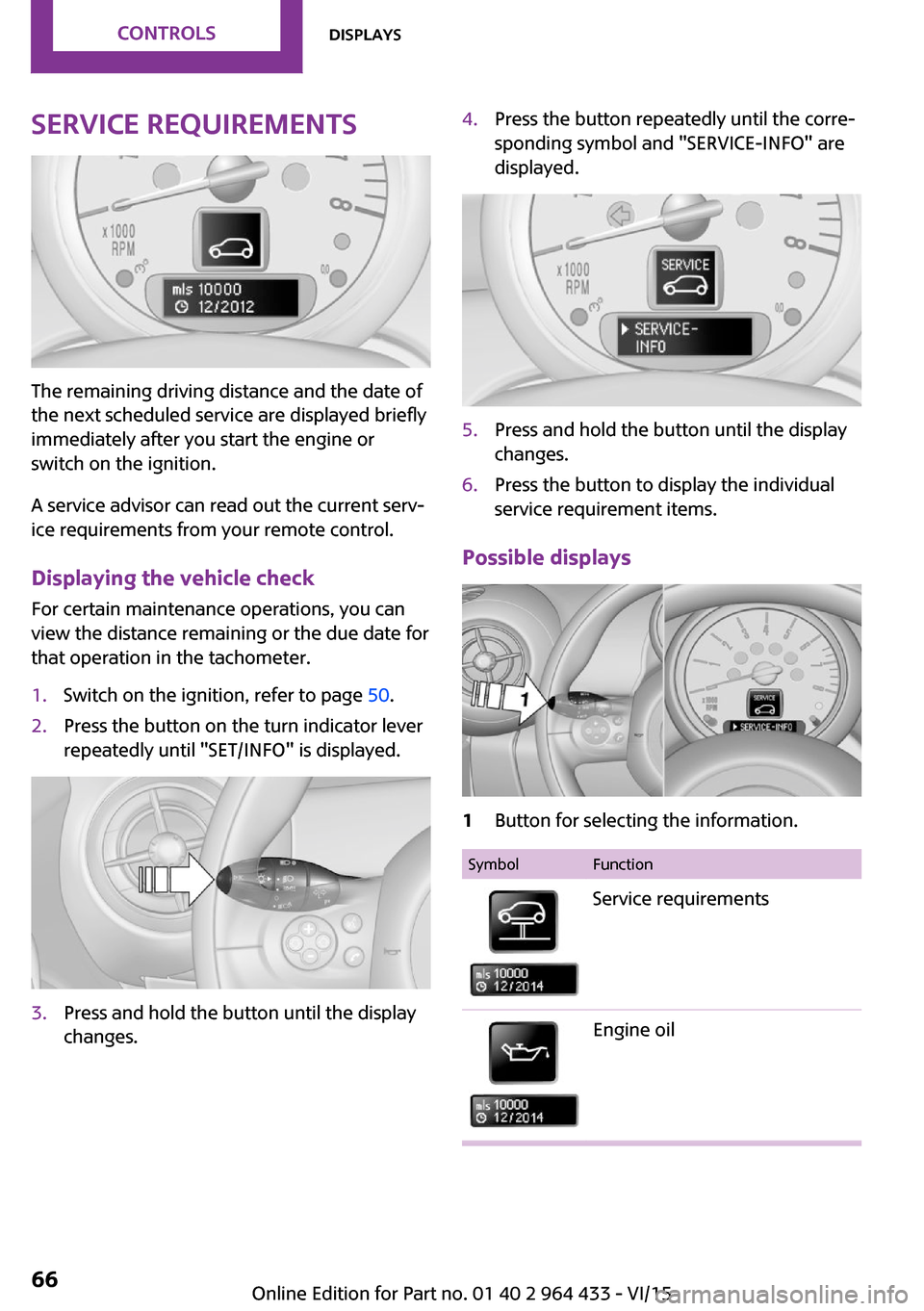
Service requirements
The remaining driving distance and the date of
the next scheduled service are displayed briefly
immediately after you start the engine or
switch on the ignition.
A service advisor can read out the current serv‐
ice requirements from your remote control.
Displaying the vehicle check
For certain maintenance operations, you can
view the distance remaining or the due date for
that operation in the tachometer.
1.Switch on the ignition, refer to page 50.2.Press the button on the turn indicator lever
repeatedly until "SET/INFO" is displayed.3.Press and hold the button until the display
changes.4.Press the button repeatedly until the corre‐
sponding symbol and "SERVICE-INFO" are
displayed.5.Press and hold the button until the display
changes.6.Press the button to display the individual
service requirement items.
Possible displays
1Button for selecting the information.SymbolFunctionService requirementsEngine oilSeite 66CONTROLSDisplays66
Online Edition for Part no. 01 40 2 964 433 - VI/15
Page 78 of 223
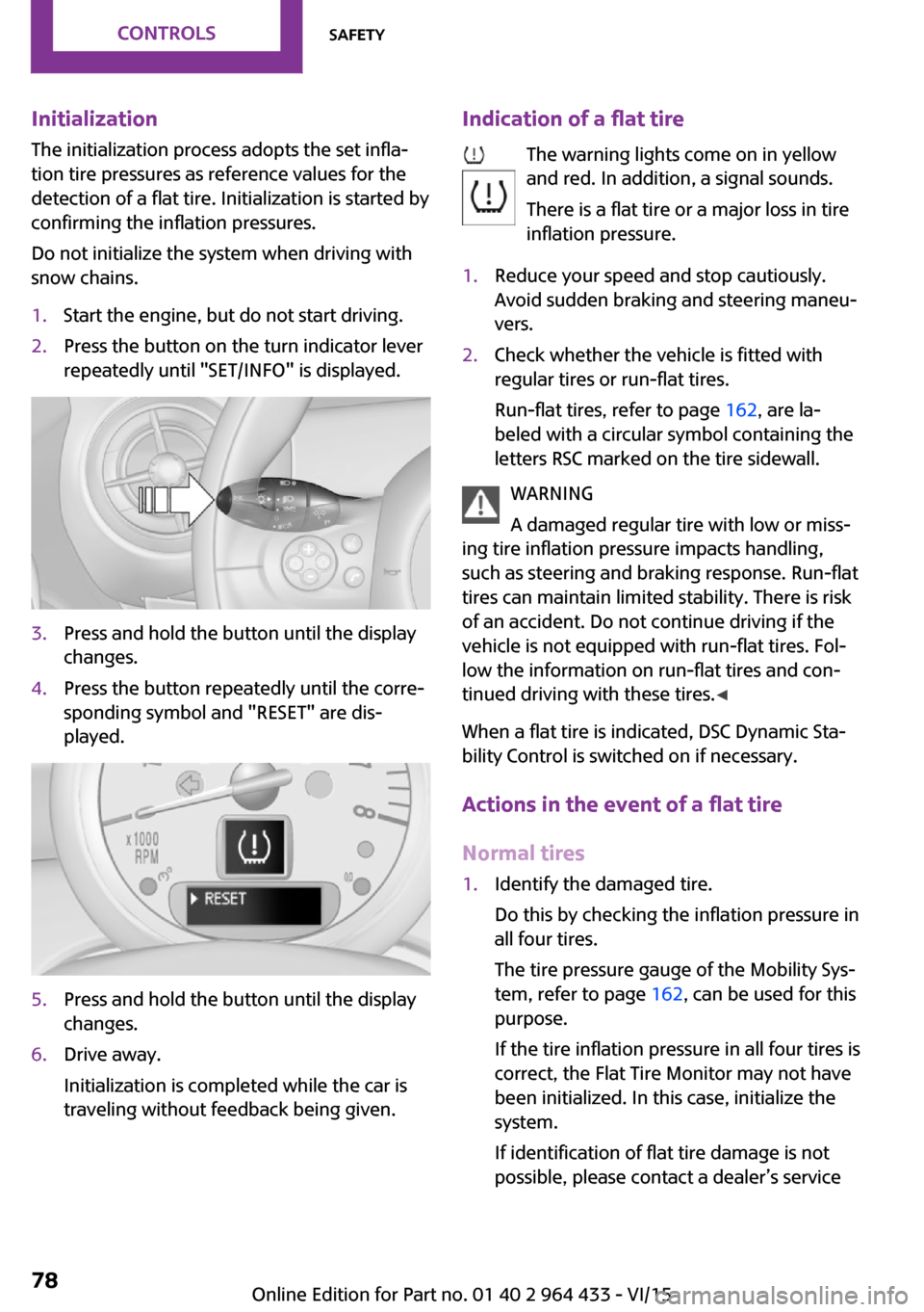
InitializationThe initialization process adopts the set infla‐
tion tire pressures as reference values for the
detection of a flat tire. Initialization is started by
confirming the inflation pressures.
Do not initialize the system when driving with
snow chains.1.Start the engine, but do not start driving.2.Press the button on the turn indicator lever
repeatedly until "SET/INFO" is displayed.3.Press and hold the button until the display
changes.4.Press the button repeatedly until the corre‐
sponding symbol and "RESET" are dis‐
played.5.Press and hold the button until the display
changes.6.Drive away.
Initialization is completed while the car is
traveling without feedback being given.Indication of a flat tire
The warning lights come on in yellow
and red. In addition, a signal sounds.
There is a flat tire or a major loss in tire
inflation pressure.1.Reduce your speed and stop cautiously.
Avoid sudden braking and steering maneu‐
vers.2.Check whether the vehicle is fitted with
regular tires or run-flat tires.
Run-flat tires, refer to page 162, are la‐
beled with a circular symbol containing the
letters RSC marked on the tire sidewall.
WARNING
A damaged regular tire with low or miss‐
ing tire inflation pressure impacts handling,
such as steering and braking response. Run-flat
tires can maintain limited stability. There is risk
of an accident. Do not continue driving if the
vehicle is not equipped with run-flat tires. Fol‐
low the information on run-flat tires and con‐
tinued driving with these tires. ◀
When a flat tire is indicated, DSC Dynamic Sta‐
bility Control is switched on if necessary.
Actions in the event of a flat tire
Normal tires
1.Identify the damaged tire.
Do this by checking the inflation pressure in
all four tires.
The tire pressure gauge of the Mobility Sys‐
tem, refer to page 162, can be used for this
purpose.
If the tire inflation pressure in all four tires is
correct, the Flat Tire Monitor may not have
been initialized. In this case, initialize the
system.
If identification of flat tire damage is not
possible, please contact a dealer’s serviceSeite 78CONTROLSSafety78
Online Edition for Part no. 01 40 2 964 433 - VI/15
Page 160 of 223
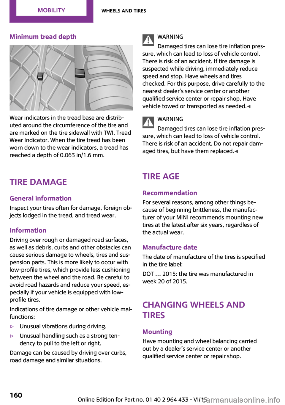
Minimum tread depth
Wear indicators in the tread base are distrib‐
uted around the circumference of the tire and
are marked on the tire sidewall with TWI, Tread
Wear Indicator. When the tire tread has been
worn down to the wear indicators, a tread has
reached a depth of 0.063 in/1.6 mm.
Tire damage
General information Inspect your tires often for damage, foreign ob‐
jects lodged in the tread, and tread wear.
Information
Driving over rough or damaged road surfaces,
as well as debris, curbs and other obstacles can
cause serious damage to wheels, tires and sus‐
pension parts. This is more likely to occur with
low-profile tires, which provide less cushioning
between the wheel and the road. Be careful to
avoid road hazards and reduce your speed, es‐
pecially if your vehicle is equipped with low-
profile tires.
Indications of tire damage or other vehicle mal‐
functions:
▷Unusual vibrations during driving.▷Unusual handling such as a strong ten‐
dency to pull to the left or right.
Damage can be caused by driving over curbs,
road damage and similar situations.
WARNING
Damaged tires can lose tire inflation pres‐
sure, which can lead to loss of vehicle control.
There is risk of an accident. If tire damage is
suspected while driving, immediately reduce
speed and stop. Have wheels and tires
checked. For this purpose, drive carefully to the
nearest dealer’s service center or another
qualified service center or repair shop. Have
vehicle towed or transported as needed. ◀
WARNING
Damaged tires can lose tire inflation pres‐
sure, which can lead to loss of vehicle control.
There is risk of an accident. Do not repair dam‐
aged tires, but have them replaced. ◀
Tire age Recommendation
For several reasons, among other things be‐
cause of beginning brittleness, the manufac‐
turer of your MINI recommends mounting new
tires at the latest after six years, regardless of
the actual wear.
Manufacture date
The date of manufacture of the tires is specified
in the tire label:
DOT … 2015: the tire was manufactured in
week 20 of 2015.
Changing wheels and
tires
Mounting
Have mounting and wheel balancing carried
out by a dealer’s service center or another
qualified service center or repair shop.Seite 160MOBILITYWheels and tires160
Online Edition for Part no. 01 40 2 964 433 - VI/15
Page 192 of 223
Correcting paint damage
Depending on the severity of the damage, re‐
pair stone impact damage or scratches imme‐
diately to prevent rust formation.
The manufacturer recommends having paint
damage corrected with a professional repair
paint job according to factory specifications us‐
ing original MINI paint materials.
Preservation Preservation is needed when water no longer
beads off of the clean paint surfaces. Only use
paint preservation products that contain car‐
nauba or synthetic waxes.
Caring for matte finishes
Only use cleaning and care products suitable
for vehicles with matte finish. These are availa‐
ble from a dealer’s service center or another
qualified service center or repair shop.
Leather care
The leather processed by the manufacturer is a
high quality natural product. Light graininess is
a typical feature of natural leather.
Particles of dust and road grime chafe in pores
and folds, and lead to increased wear and pre‐
mature degradation of the leather surface.
Therefore, remove dust from the leather regu‐
larly, using a cloth or vacuum cleaner.
Make especially sure that light-colored leather
is cleaned regularly as it is more susceptible to
soiling.
Twice a year, treat the leather with a leather lo‐
tion as dirt and grease will attack the protective
layer of the leather.
Upholstery material care
Vacuum regularly with a vacuum cleaner to re‐
move superficial soiling.
In case of heavy soiling, e.g., beverage stains,
use a soft sponge or lint-free microfiber cloth incombination with a suitable interior cleaner.
Follow the instructions on the container.
Clean the upholstery material down to the
seams using large sweeping motions. Avoid
rubbing the material vigorously.
CAUTION
Open Velcro® fasteners on articles of
clothing can damage the seat covers. There is risk of property damage. Ensure that any Vel‐
cro® fasteners are closed. ◀
Caring for special components Interior plastic parts
These include:▷Imitation leather surfaces▷Lamp lenses▷Indicator covers▷Matte components
Clean with water and a solvent-free plastic
cleaner if necessary.
Rubber seals
Only treat with water or a rubber care product.
When cleaning rubber seals, do not use silicone
sprays or other care products containing sili‐
cone; otherwise, noise and damage may result.
Chrome surfaces Carefully clean components such as the radia‐
tor grille or door handles with an ample supply
of water, possibly with shampoo added, partic‐
ularly when they have been exposed to road
salt. For additional treatment, use a chrome
polish.
Light-alloy wheels
When cleaning the wheels on the vehicle, only
use a neutral wheel rim cleaner with a pH value
of 5 to 9.
Seite 192MOBILITYCare192
Online Edition for Part no. 01 40 2 964 433 - VI/15
Page 195 of 223
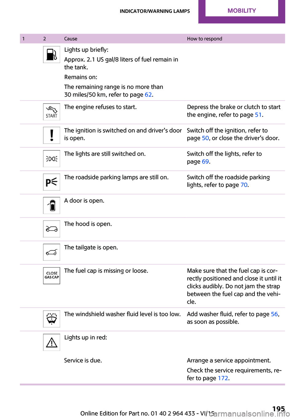
12CauseHow to respondLights up briefly:
Approx. 2.1 US gal/8 liters of fuel remain in
the tank.
Remains on:
The remaining range is no more than
30 miles/50 km, refer to page 62.The engine refuses to start.Depress the brake or clutch to start
the engine, refer to page 51.The ignition is switched on and driver's door
is open.Switch off the ignition, refer to
page 50, or close the driver's door.The lights are still switched on.Switch off the lights, refer to
page 69.The roadside parking lamps are still on.Switch off the roadside parking
lights, refer to page 70.A door is open.The hood is open.The tailgate is open.The fuel cap is missing or loose.Make sure that the fuel cap is cor‐
rectly positioned and close it until it
clicks audibly. Do not jam the strap
between the fuel cap and the vehi‐
cle.The windshield washer fluid level is too low.Add washer fluid, refer to page 56,
as soon as possible.Lights up in red:Service is due.Arrange a service appointment.
Check the service requirements, re‐
fer to page 172.Seite 195Indicator/warning lampsMOBILITY195
Online Edition for Part no. 01 40 2 964 433 - VI/15
Page 196 of 223
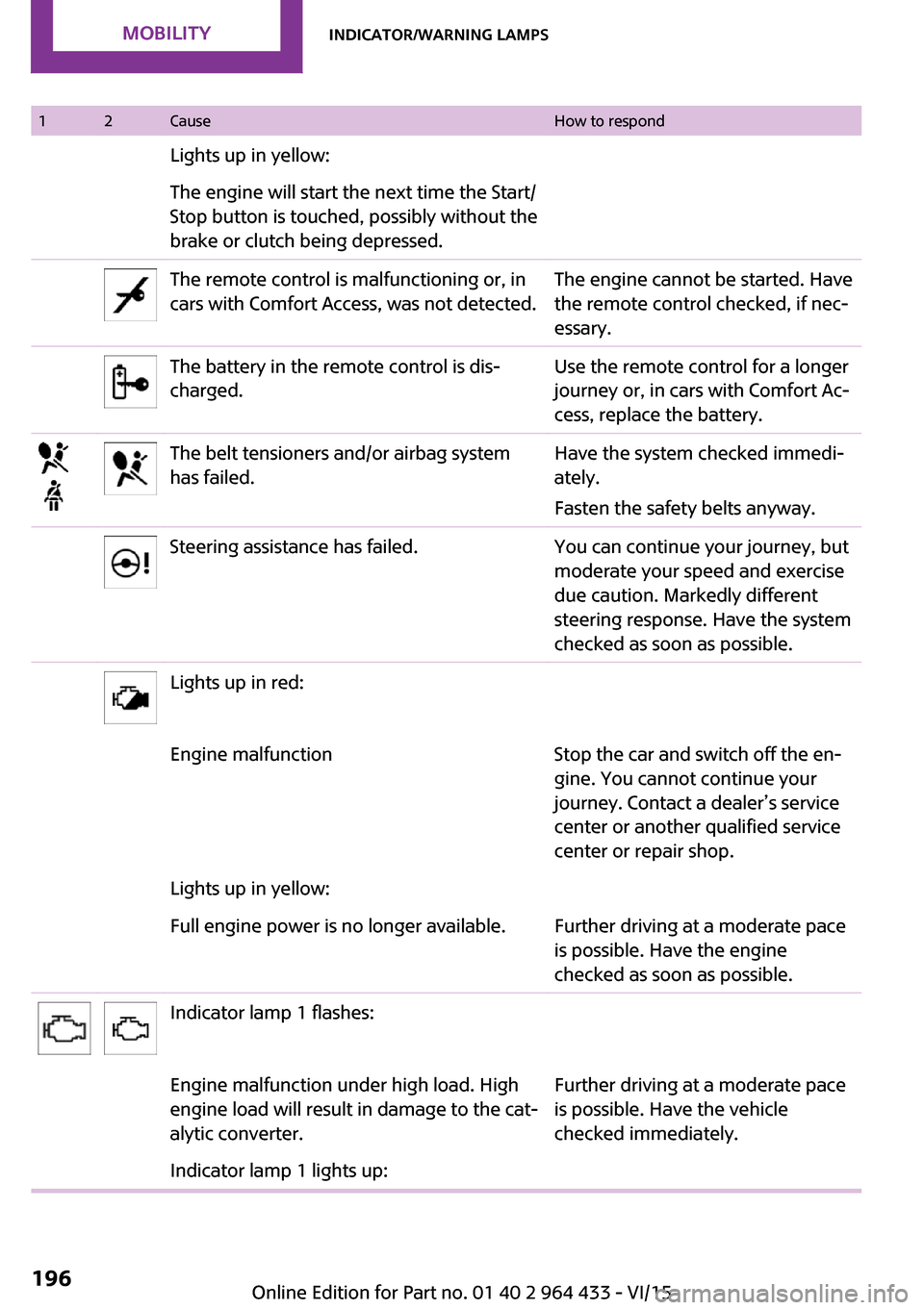
12CauseHow to respondLights up in yellow:The engine will start the next time the Start/
Stop button is touched, possibly without the
brake or clutch being depressed.The remote control is malfunctioning or, in
cars with Comfort Access, was not detected.The engine cannot be started. Have
the remote control checked, if nec‐
essary.The battery in the remote control is dis‐
charged.Use the remote control for a longer
journey or, in cars with Comfort Ac‐
cess, replace the battery.The belt tensioners and/or airbag system
has failed.Have the system checked immedi‐
ately.
Fasten the safety belts anyway.Steering assistance has failed.You can continue your journey, but
moderate your speed and exercise
due caution. Markedly different
steering response. Have the system
checked as soon as possible.Lights up in red:Engine malfunctionStop the car and switch off the en‐
gine. You cannot continue your
journey. Contact a dealer’s service
center or another qualified service
center or repair shop.Lights up in yellow:Full engine power is no longer available.Further driving at a moderate pace
is possible. Have the engine
checked as soon as possible.Indicator lamp 1 flashes:Engine malfunction under high load. High
engine load will result in damage to the cat‐
alytic converter.Further driving at a moderate pace
is possible. Have the vehicle
checked immediately.Indicator lamp 1 lights up:Seite 196MOBILITYIndicator/warning lamps196
Online Edition for Part no. 01 40 2 964 433 - VI/15