oil MINI Roadster 2014 Owner's Manual
[x] Cancel search | Manufacturer: MINI, Model Year: 2014, Model line: Roadster, Model: MINI Roadster 2014Pages: 224, PDF Size: 5.46 MB
Page 5 of 224
ContentsThe fastest way to find information on a partic‐
ular topic or item is by using the index, refer to
page 214.6Notes
At a glance
12Cockpit
Controls
20Opening and closing44Adjusting50Transporting children safely55Driving65Displays74Lamps80Safety89Driving stability control systems93Driving comfort96Climate102Interior equipment106Storage compartments
Driving tips
112Things to remember when driving116Loading119Saving fuel
Entertainment
124Radio MINI Boost CD
Communication
138TelephoneMobility150Refueling152Fuel154Wheels and tires168Engine compartment170Engine oil172Coolant173Maintenance175Replacing components186Breakdown assistance191Care196Indicator/warning lamps
Reference
210Technical data214Everything from A to Z
Online Edition for Part no. 01 40 2 911 475 - VI/13
Page 7 of 224
tain country you cannot lodge warranty claims
for your vehicle there. Further information can
be obtained from your Service Centre.
Maintenance and repairs Advanced technology, e.g., the use of modern
materials and high-performance electronics,
requires suitable maintenance and repair
methods.
Therefore, have this work performed only by a
MINI service center or a workshop that works
according to MINI repair procedures with ap‐
propriately trained personnel.
If this work is not carried out properly, there is
the danger of subsequent damage and related
safety hazards.
Parts and accessories
For your own safety, use genuine parts and ac‐
cessories approved by the manufacturer of the
MINI. When you purchase accessories tested
and approved by the manufacturer of the MINI
and Original MINI Parts, you simultaneously ac‐
quire the assurance that they have been thor‐ oughly tested by the manufacturer of the MINI
to ensure optimum performance when instal‐
led on your vehicle. The manufacturer of the
MINI warrants these parts to be free from de‐
fects in material and workmanship. The manu‐
facturer of the MINI will not accept any liability
for damage resulting from installation of parts
and accessories not approved by the manufac‐
turer of the MINI. The manufacturer of the MINI
cannot test every product made by other man‐
ufacturers to verify if it can be used on a MINI
safely and without risk to either the vehicle, its
operation, or its occupants. Original MINI Parts,
MINI Accessories and other products approved
by the manufacturer of the MINI, together with
professional advice on using these items, are
available from all MINI Dealers. Installation and
operation of non-MINI approved accessories
such as alarms, radios, amplifiers, radar detec‐
tors, wheels, suspension components, brake
dust shields, telephones, including operation ofany mobile phone from within the vehicle with‐
out using an externally mounted antenna, or
transceiver equipment, for instance, CBs,
walkie-talkies, ham radios or similar accesso‐
ries, may cause extensive damage to the vehi‐
cle, compromise its safety, interfere with the
vehicle's electrical system or affect the validity
of the MINI Limited Warranty. See your MINI
Dealer for additional information. Maintenance,
replacement, or repair of the emission control
devices and systems may be performed by any
automotive repair establishment or individual
using any certified automotive part.
California Proposition 65 Warning
California laws require us to state the following
warning:
Engine exhaust and a wide variety of automo‐
bile components and parts, including compo‐
nents found in the interior furnishings in a vehi‐
cle, contain or emit chemicals known to the
State of California to cause cancer and birth de‐
fects and reproductive harm. In addition, cer‐
tain fluids contained in vehicles and certain
products of component wear contain or emit
chemicals known to the State of California to
cause cancer and birth defects or other repro‐
ductive harm. Battery posts, terminals and re‐
lated accessories contain lead and lead com‐
pounds. Wash your hands after handling. Used
engine oil contains chemicals that have caused
cancer in laboratory animals. Always protect
your skin by washing thoroughly with soap and
water.
Service and warranty We recommend that you read this publication
thoroughly. Your vehicle is covered by the fol‐
lowing warranties:▷New Vehicle Limited Warranty.▷Rust Perforation Limited Warranty.▷Federal Emissions System Defect Warranty.▷Federal Emissions Performance Warranty.Seite 7Notes7
Online Edition for Part no. 01 40 2 911 475 - VI/13
Page 16 of 224
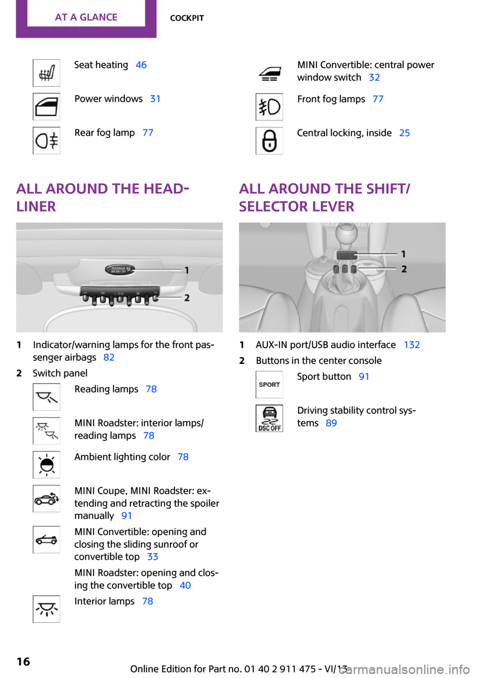
Seat heating 46Power windows 31Rear fog lamp 77MINI Convertible: central power
window switch 32Front fog lamps 77Central locking, inside 25All around the head‐
liner1Indicator/warning lamps for the front pas‐
senger airbags 822Switch panelReading lamps 78MINI Roadster: interior lamps/
reading lamps 78Ambient lighting color 78MINI Coupe, MINI Roadster: ex‐
tending and retracting the spoiler
manually 91MINI Convertible: opening and
closing the sliding sunroof or
convertible top 33
MINI Roadster: opening and clos‐
ing the convertible top 40Interior lamps 78All around the shift/
selector lever1AUX-IN port/USB audio interface 1322Buttons in the center consoleSport button 91Driving stability control sys‐
tems 89Seite 16At a glanceCockpit16
Online Edition for Part no. 01 40 2 911 475 - VI/13
Page 33 of 224
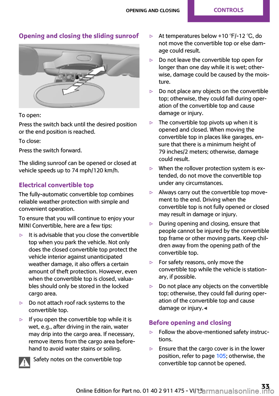
Opening and closing the sliding sunroof
To open:
Press the switch back until the desired position
or the end position is reached.
To close:
Press the switch forward.
The sliding sunroof can be opened or closed at
vehicle speeds up to 74 mph/120 km/h.
Electrical convertible top The fully-automatic convertible top combines
reliable weather protection with simple and convenient operation.
To ensure that you will continue to enjoy your
MINI Convertible, here are a few tips:
▷It is advisable that you close the convertible
top when you park the vehicle. Not only
does the closed convertible top protect the
vehicle interior against unanticipated
weather damage, it also offers a certain
amount of theft protection. However, even
when the convertible top is closed, valua‐
bles should only be stored in the locked
cargo area.▷Do not attach roof rack systems to the
convertible top.▷If you open the convertible top while it is
wet, e.g., after driving in the rain, water
may drip into the cargo area. If necessary,
remove items from the cargo area before‐
hand to avoid water stains or soiling.
Safety notes on the convertible top
▷At temperatures below +10 ℉/-12 ℃, do
not move the convertible top or else dam‐
age could result.▷Do not leave the convertible top open for
longer than one day while it is wet; other‐
wise, damage could be caused by the mois‐
ture.▷Do not place any objects on the convertible
top; otherwise, they could fall during oper‐
ation of the convertible top and cause
damage or injury.▷The convertible top pivots up when it is
opened and closed. When moving the
convertible top in places like garages, en‐
sure that there is a minimum height of
79 inches/2 meters; otherwise, damage
could result.▷When the rollover protection system is ex‐
tended, do not move the convertible top
under any circumstances.▷Always carry out the convertible top move‐
ment to the end. Driving when the
convertible top is not fully opened or closed
may result in damage or injury.▷During opening and closing, ensure that
people cannot be injured by the convertible
top frame or other moving parts. Keep chil‐
dren away from the opening path of the
convertible top.▷For safety reasons, only move the
convertible top while the vehicle is station‐
ary, if possible.▷Do not place any objects on the convertible
top; otherwise, they could fall during oper‐
ation of the convertible top and cause
damage or injury. ◀
Before opening and closing
▷Follow the above-mentioned safety instruc‐
tions.▷Ensure that the cargo cover is in the lower
position, refer to page 105; otherwise, the
convertible top cannot be opened.Seite 33Opening and closingControls33
Online Edition for Part no. 01 40 2 911 475 - VI/13
Page 71 of 224
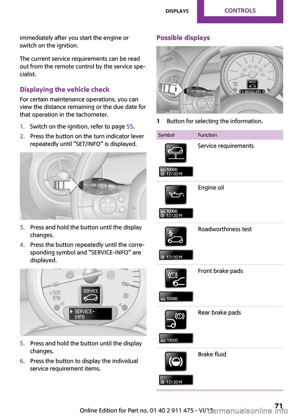
immediately after you start the engine or
switch on the ignition.
The current service requirements can be read
out from the remote control by the service spe‐
cialist.
Displaying the vehicle check
For certain maintenance operations, you can
view the distance remaining or the due date for
that operation in the tachometer.1.Switch on the ignition, refer to page 55.2.Press the button on the turn indicator lever
repeatedly until "SET/INFO" is displayed.3.Press and hold the button until the display
changes.4.Press the button repeatedly until the corre‐
sponding symbol and "SERVICE-INFO" are
displayed.5.Press and hold the button until the display
changes.6.Press the button to display the individual
service requirement items.Possible displays1Button for selecting the information.SymbolFunctionService requirementsEngine oilRoadworthiness testFront brake padsRear brake padsBrake fluidSeite 71DisplaysControls71
Online Edition for Part no. 01 40 2 911 475 - VI/13
Page 91 of 224
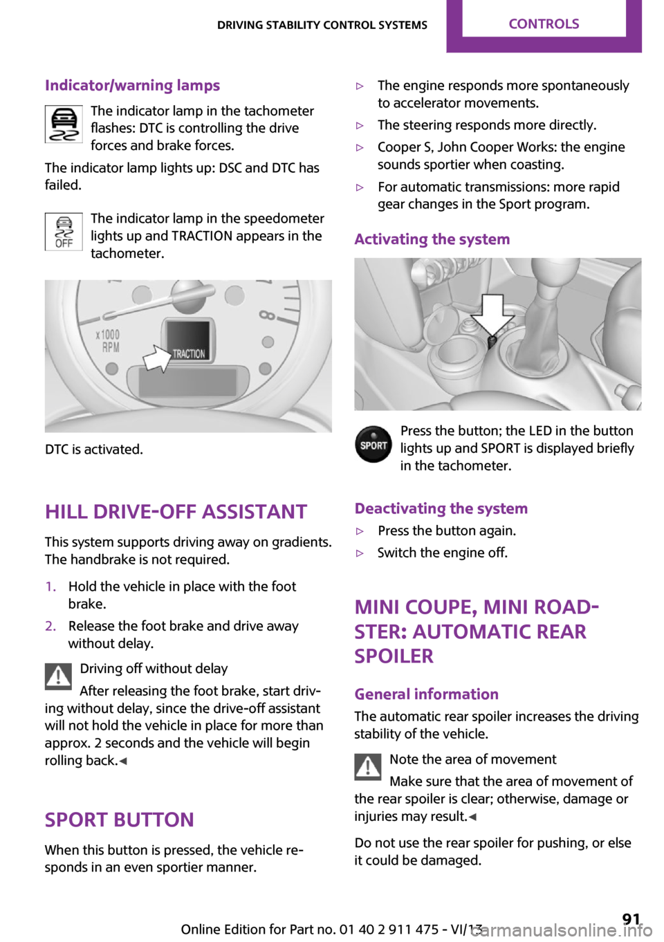
Indicator/warning lampsThe indicator lamp in the tachometer
flashes: DTC is controlling the drive
forces and brake forces.
The indicator lamp lights up: DSC and DTC has
failed.
The indicator lamp in the speedometer
lights up and TRACTION appears in the
tachometer.
DTC is activated.
Hill drive-off assistant This system supports driving away on gradients.
The handbrake is not required.
1.Hold the vehicle in place with the foot
brake.2.Release the foot brake and drive away
without delay.
Driving off without delay
After releasing the foot brake, start driv‐
ing without delay, since the drive-off assistant
will not hold the vehicle in place for more than
approx. 2 seconds and the vehicle will begin
rolling back. ◀
Sport button
When this button is pressed, the vehicle re‐
sponds in an even sportier manner.
▷The engine responds more spontaneously
to accelerator movements.▷The steering responds more directly.▷Cooper S, John Cooper Works: the engine
sounds sportier when coasting.▷For automatic transmissions: more rapid
gear changes in the Sport program.
Activating the system
Press the button; the LED in the button
lights up and SPORT is displayed briefly
in the tachometer.
Deactivating the system
▷Press the button again.▷Switch the engine off.
MINI Coupe, MINI Road‐
ster: automatic rear
spoiler
General information The automatic rear spoiler increases the driving
stability of the vehicle.
Note the area of movement
Make sure that the area of movement of
the rear spoiler is clear; otherwise, damage or
injuries may result. ◀
Do not use the rear spoiler for pushing, or else
it could be damaged.
Seite 91Driving stability control systemsControls91
Online Edition for Part no. 01 40 2 911 475 - VI/13
Page 92 of 224
Notes on the car washes and care, refer to
page 191.
Automatic operation
If the rear spoiler is retracted, it is in automatic
mode when the engine is started. In this case,
the system is initialized when the vehicle is set
into motion; this may cause a short noise to be heard.
Automatic extension:
When the vehicle exceeds a speed of ap‐
prox. 50 mph/80 km/h.
Automatic retraction:
When the vehicle drops below a speed of ap‐
prox. 38 mph/60 km/h.
The rear spoiler cannot be manually retracted
in automatic mode at speeds above
38 mph/60 km/h.
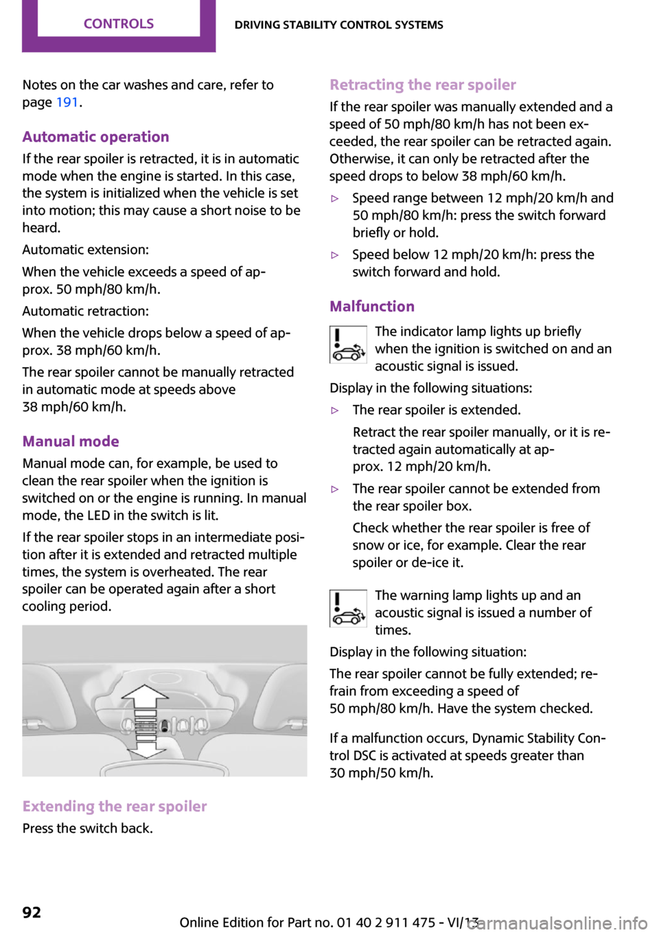
Manual mode Manual mode can, for example, be used to
clean the rear spoiler when the ignition is
switched on or the engine is running. In manual
mode, the LED in the switch is lit.
If the rear spoiler stops in an intermediate posi‐
tion after it is extended and retracted multiple
times, the system is overheated. The rear
spoiler can be operated again after a short
cooling period.
Extending the rear spoiler
Press the switch back.
Retracting the rear spoiler
If the rear spoiler was manually extended and a
speed of 50 mph/80 km/h has not been ex‐
ceeded, the rear spoiler can be retracted again.
Otherwise, it can only be retracted after the
speed drops to below 38 mph/60 km/h.▷Speed range between 12 mph/20 km/h and
50 mph/80 km/h: press the switch forward
briefly or hold.▷Speed below 12 mph/20 km/h: press the
switch forward and hold.
Malfunction
The indicator lamp lights up briefly
when the ignition is switched on and an
acoustic signal is issued.
Display in the following situations:
▷The rear spoiler is extended.
Retract the rear spoiler manually, or it is re‐
tracted again automatically at ap‐
prox. 12 mph/20 km/h.▷The rear spoiler cannot be extended from
the rear spoiler box.
Check whether the rear spoiler is free of
snow or ice, for example. Clear the rear
spoiler or de-ice it.
The warning lamp lights up and an
acoustic signal is issued a number of
times.
Display in the following situation:
The rear spoiler cannot be fully extended; re‐
frain from exceeding a speed of
50 mph/80 km/h. Have the system checked.
If a malfunction occurs, Dynamic Stability Con‐
trol DSC is activated at speeds greater than
30 mph/50 km/h.
Seite 92ControlsDriving stability control systems92
Online Edition for Part no. 01 40 2 911 475 - VI/13
Page 164 of 224
Maximum speed of winter tires
If the maximum speed of the vehicle is higher
than the permissible speed for the winter tires,
then display a corresponding sign in the field of
vision. You can obtain this sign from the tire
specialist or from your service center.
Maximum speed for winter tires
Do not exceed the maximum speed for
the winter tires; otherwise, tire damage and ac‐
cidents can occur. ◀
Run-flat tires When mounting new tires or changing fromsummer to winter tires or vice versa, use run-
flat tires for your own safety. Also, a compact
wheel is not available in case of a flat tire. Your
service center will be glad to advise you.
Rotating wheels between axles
Different wear patterns occur on the front and
rear axles, depending on the individual condi‐
tions of use.
To ensure even wear on the tires, the wheels
can be rotated between the axles. Your service
center will be glad to advise you.
After changing the tires, check the tire inflation
pressure and correct it if necessary.
Storage Store wheels and tires in a cool, dry place with
as little exposure to light as possible.
Always protect tires against all contact with oil,
grease and fuels.
Do not exceed the maximum tire inflation pres‐
sure indicated on the side wall of the tire.Run-flat tires
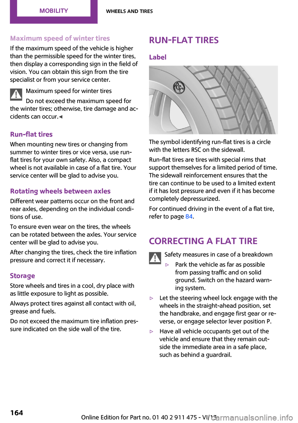
Label
The symbol identifying run-flat tires is a circle
with the letters RSC on the sidewall.
Run-flat tires are tires with special rims that
support themselves for a limited period of time.
The sidewall reinforcement ensures that the
tire can continue to be used to a limited extent
if it has lost pressure and even if it has become
completely depressurized.
For continued driving in the event of a flat tire,
refer to page 84.
Correcting a flat tire Safety measures in case of a breakdown
▷Park the vehicle as far as possible
from passing traffic and on solid
ground. Switch on the hazard warn‐
ing system.▷Let the steering wheel lock engage with the
wheels in the straight-ahead position, set
the handbrake, and engage first gear or re‐
verse, or engage selector lever position P.▷Have all vehicle occupants get out of the
vehicle and ensure that they remain out‐
side the immediate area in a safe place,
such as behind a guardrail.Seite 164MobilityWheels and tires164
Online Edition for Part no. 01 40 2 911 475 - VI/13
Page 168 of 224
Engine compartmentVehicle equipment
This chapter describes all series equipment as
well as country-specific and special equipment
offered for this model series.Therefore, it alsodescribes equipment that may not be found in
your vehicle, for instance due to the selected
special equipment or the country version. This
also applies to safety-related functions and sys‐
tems.
Important features in the engine compartment
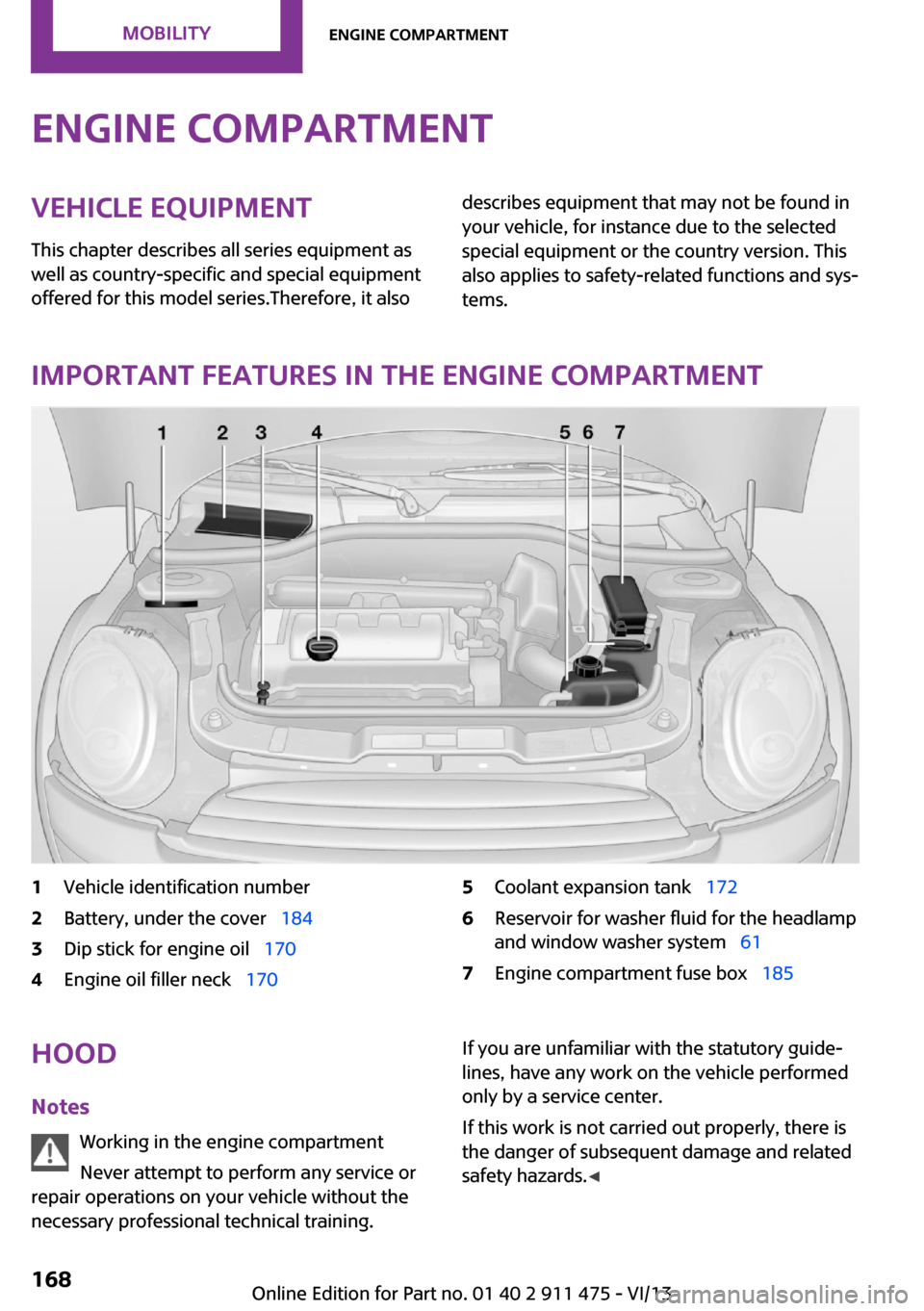
1Vehicle identification number2Battery, under the cover 1843Dip stick for engine oil 1704Engine oil filler neck 1705Coolant expansion tank 1726Reservoir for washer fluid for the headlamp
and window washer system 617Engine compartment fuse box 185Hood
Notes Working in the engine compartment
Never attempt to perform any service or
repair operations on your vehicle without the
necessary professional technical training.If you are unfamiliar with the statutory guide‐
lines, have any work on the vehicle performed
only by a service center.
If this work is not carried out properly, there is
the danger of subsequent damage and related
safety hazards. ◀Seite 168MobilityEngine compartment168
Online Edition for Part no. 01 40 2 911 475 - VI/13
Page 170 of 224
Engine oilVehicle equipment
This chapter describes all series equipment as
well as country-specific and special equipment
offered for this model series.Therefore, it also
describes equipment that may not be found in
your vehicle, for instance due to the selected
special equipment or the country version. This
also applies to safety-related functions and sys‐
tems.
Engine oil General information
Engine oil consumption depends on the driving
style and the conditions of use. A highly sporty
driving style, for example, results in considera‐
bly higher engine oil consumption.
Therefore, regularly check the engine oil level
after refueling.
Checking the oil level with a dip stick1.Park the vehicle on level ground when the
engine is at operating temperature, i.e., af‐
ter driving continuously for at least
6 2 miles/10 km.2.Switch the engine off.3.After approx. 5 minutes, pull out the dip
stick and wipe it off with a lint-free cloth,
paper towel, etc.4.Carefully insert the dip stick all the way into
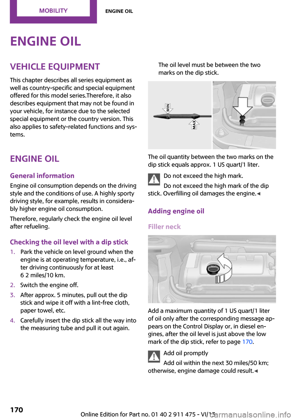
the measuring tube and pull it out again.The oil level must be between the two
marks on the dip stick.
The oil quantity between the two marks on the
dip stick equals approx. 1 US quart/1 liter.
Do not exceed the high mark.
Do not exceed the high mark of the dip
stick. Overfilling oil damages the engine. ◀
Adding engine oil
Filler neck
Add a maximum quantity of 1 US quart/1 liter
of oil only after the corresponding message ap‐
pears on the Control Display or, in diesel en‐
gines, after the oil level is just above the low
mark of the dip stick, refer to page 170.
Add oil promptly
Add oil within the next 30 miles/50 km;
otherwise, engine damage could result. ◀
Seite 170MobilityEngine oil170
Online Edition for Part no. 01 40 2 911 475 - VI/13