ECO mode MITSUBISHI 3000GT 1992 2.G User Guide
[x] Cancel search | Manufacturer: MITSUBISHI, Model Year: 1992, Model line: 3000GT, Model: MITSUBISHI 3000GT 1992 2.GPages: 738, PDF Size: 35.06 MB
Page 308 of 738
Downloaded from www.Manualslib.com manuals search engine CIRCUIT DIAGRAMS - Full Auto Air Conditionina Circuit
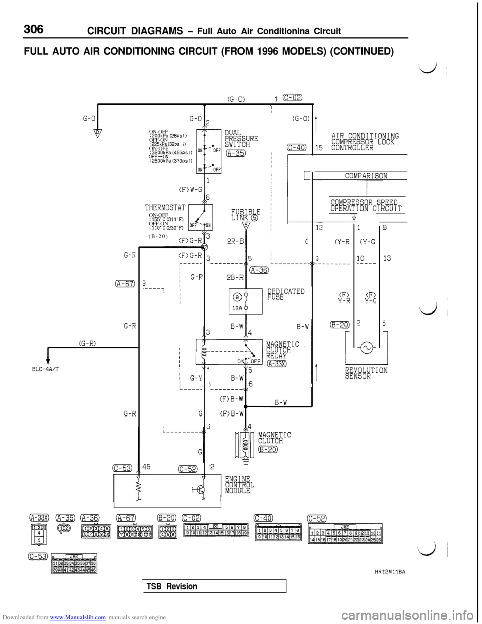
FULL AUTO AIR CONDITIONING CIRCUIT (FROM 1996 MODELS) (CONTINUED)
(G-0)l(c-02)
IT1/
G-I;
(A-67)
G-R
(G-R)
1ELC-4A/T
G-RG
G-O 2I(G-0)
ON-OFF:200kPa (28DS i)OFF-ON:2%kPa (32~s i )ON-OFF
1
(F>W-G,p,\THERMOSTATON-OFF
:155'C(31l'F)OFF-ON
:llO'C(230'F)OFF 'toN(B-20)
3.----1
(F>G-Rcl------I)j G-FI/II/
r.--------_
1 G-k
L---..
G
(c-52)
*
DUALPRyQR$;RE
(A-35)(c-40)IIIII
--------
I6--------
rCOMPARISON
C
B&~k”“‘“”
'2x
ENGINECONTROLMODULE
AIR CONDITIONINGCOMPRESSOR LOCK15 CONTROLLER
COMPRESSOR SPEEDOPERATION CIRCUIT
(Y-R
1
(Y-G
10_----
(F>
-cl-f-b
3Q
13
TSB RevisionHR'I2MllBA
Page 310 of 738
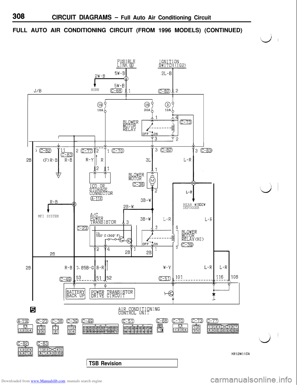
Downloaded from www.Manualslib.com manuals search engine CIRCUIT DIAGRAMS - Full Auto Air Conditioning CircuitFULL AUTO AIR CONDITIONING CIRCUIT (FROM 1996 MODELS) (CONTINUED)
\
‘d ~
2W-B2L-B
5W-B
J/0HORN(c-68) ,,l(c-82),, 2
R-B
MFI SYSTEM
2B
R-E
1
6310A
4
iFBR(c-73)
RELAY
\,&\/T- \I
J2(c-77)2-- 10"3 (c-83)
IR-Y Ri,2 ,,lI\ /\
IOD ORSTORAGECONNECTOR
(A-11X)
L-R
t
34
L-R
A/CPOWERTRANSISTOR ,.33B-WL-R
c-23),\ 3I\2A- - - - - - - -,
\,\/OFF-:,ON
"2 "4"12B" 12B
).85B-G B-RW-Y
(c-51)
REAR WiNDOWDEFOGGER
L-K
4
I
k%"RELAYCHI)
,m
L-RL-R
101116108-
AIR CONDITIONINGCONTROL UNIT
(c-se)0HRlPMllCA
1 TSB Revision
Page 358 of 738
Downloaded from www.Manualslib.com manuals search engine 356CIRCUIT DIAGRAMS - Electronic Control Suspension (ECS) Circuit
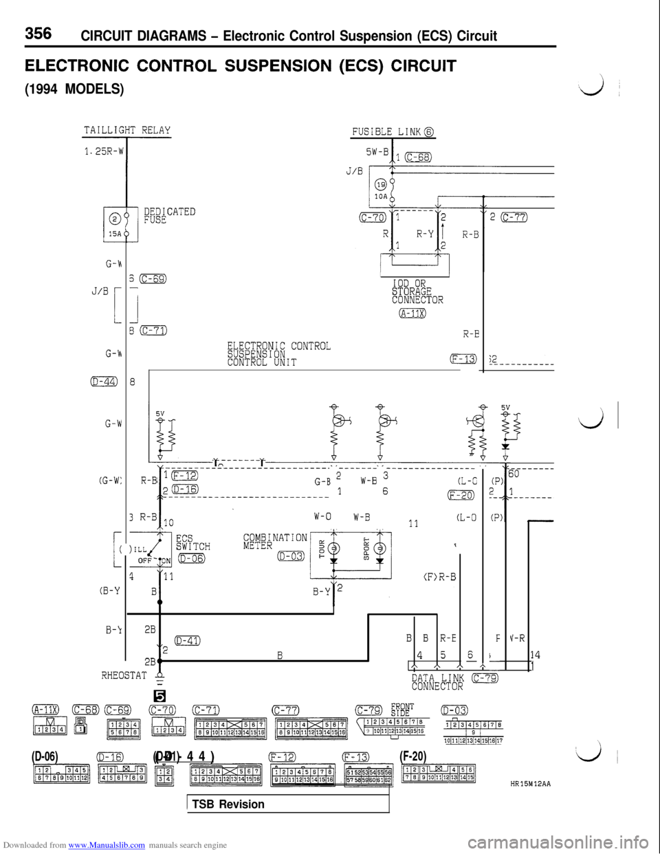
ELECTRONIC CONTROL SUSPENSION (ECS) CIRCUIT
(1994 MODELS)
FUSIBLE [email protected]
G-h
J/BL
G-k
s(c-69)-
1
80
(D-44)8
G-W
(G-W:
3R-B10 l------l 1o W-B 11 (L-0W-O
L
(
(B-Y
B-k
IIIOD ORSTORAGECONNECTOR
(A-11X)
R-B
ELECTRONIC CONTROLSUSPENSIONCONTROL UNIT(F-;2---------
4
-
(P2_-.
(P
F
\-
3
----------------------------- ------- ----------------
R-B ‘(F-12)
p(D-16)G-B 2
I-----------:----------------
W-B 3(L-C1 6(F-20)
I
2B
“2 ma
B B R-E
2BtB4 5A A A
V-R
6-14
1h
RHEOSTATA=DATA LINK (c-7CONNECTOR
(A-11X)(c-70)(D-03)11213/41516/716n
9 ~10~11~12~13j14/15~16112]31415161716
u1 2 110~11/12/13/~4~15)16~17
(D-06)(D-16)
(D-41)(D-44)(F-m(F-20)
HR15M12AA
1 TSB Revision
Page 362 of 738
Downloaded from www.Manualslib.com manuals search engine 360CIRCUIT DIAGRAMS - Electronic Control Suspension (ECS) Circuit
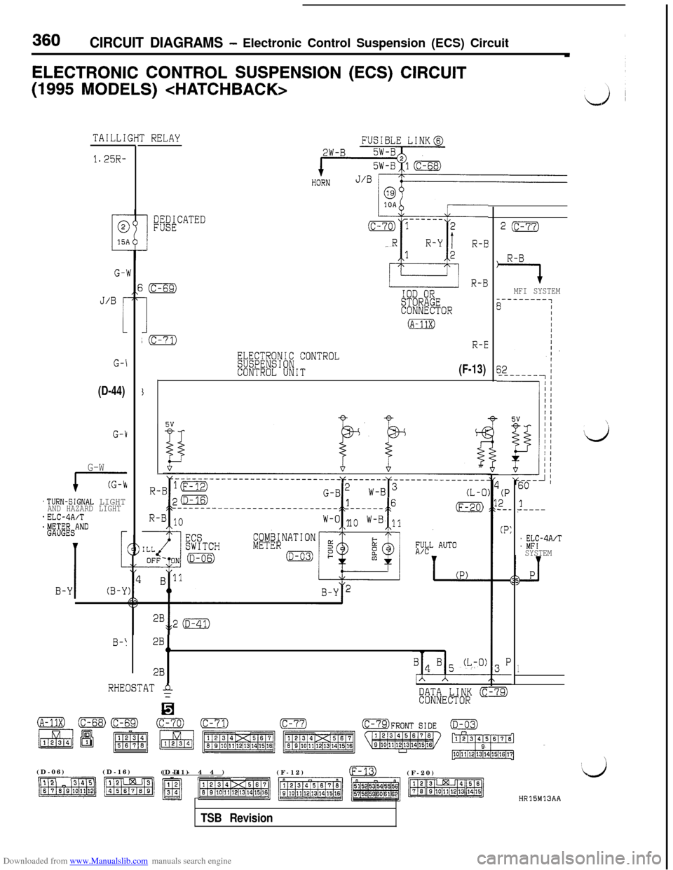
ELECTRONIC CONTROL SUSPENSION (ECS) CIRCUIT(1995
MODELS)
TAILLI
1.25R-
G-1
J/B r
1
G-\
(D-44)
G-1
G-W
17
.TURN-SIGNAL LIGHTAND HAZARD LIGHT*ELC-4A/T$&ANDr
I
1
B-Y(B-Y
0-I
r RELAY
mACATED
i(c-69)
I
IOD ORSTORAGECONNECTOR
(A-11x)
;(c-71)R-E
ELECTRONIC CONTROLSUSPENSIONCONTROL UNIT(F-13)
G-B2 w
c t
16---------------------------- ---___(F-20)
W-O 1o W-B 11
2B1h
2B
RHEOSTAT $
H
DATA LINK cCONNECTOR
2(c-77)
R-B
7MFI SYSTEM
(P2_-_
(P:
60
1?-----
: %?-4A’TSYSTEM
1
\(D-06)(D-16)
(D-41)(D-44)
(F-12)
m(F-20)
HR15M13AA
TSB Revision
Page 381 of 738
Downloaded from www.Manualslib.com manuals search engine CIRCUIT DIAGRAMS - Auto-cruise Control Circuit379AUTO-CRUISE
CONTROL
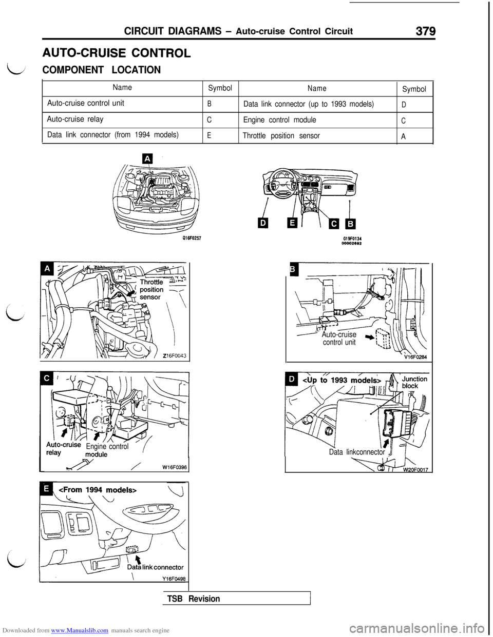
COMPONENT LOCATION
Name
Auto-cruise control unit
Auto-cruise relay
Data link connector (from 1994 models)Symbol
NameSymbol
BData link connector (up to 1993 models)D
CEngine control moduleC
E
Throttle position sensor
APlGFO257
o-cruiseEngine control
%Y /W16FO396
wow.ee2
m?zYili .[L Auto-cruisecontrol unit1ul’-~,;>
\ \\\ 1I!,- ii i-*uwl
Data linkconnector J
-0017
TSB Revision
Page 469 of 738
Downloaded from www.Manualslib.com manuals search engine ENGINE ELECTRICAL - Starting System16-23
OPERATION
L
0For models equipped with the M/T, the clutch
pedal position switch contact is switched OFF
when the clutch pedal is depressed; when the
ignition switch is then switched to the “ST’ posi-tion, electricity flows to the starter relay and
the starter motor, the contact (magnetic switch)of the starter is switched ON and the starter
motor is activated.
NOTEIf the ignition switch is switched to the “ST
position without the clutch pedal being de-
pressed, electricity flows to the starter relay
(coil), the clutch pedal position switch (contacts)
and to ground, with the result that the contacts
of the starter relay are switched OFF, and, be-
cause the power to the starter motor is thereby
interrupted, the starter motor is not activated.lFor models equipped with the
AIT, when the
ignition switch is switched to the “ST’ position
while the selector lever is at the “P” or “N” posi-
tion, the contact (magnetic switch) of the starter
is switched ON and the starter motor is activated.
TROUBLESHOOTING HINTSThe starter motor does not operate at all.
l Check the starter (coil).
lCheck for poor contact at the battery terminals
and starter.l Check Park/Neutral position switch.
l Check clutch pedal position switch.
l Check starter relay.
l Check theft-alarm starter relay.
l Check key reminder switch.
i
/’
L&J
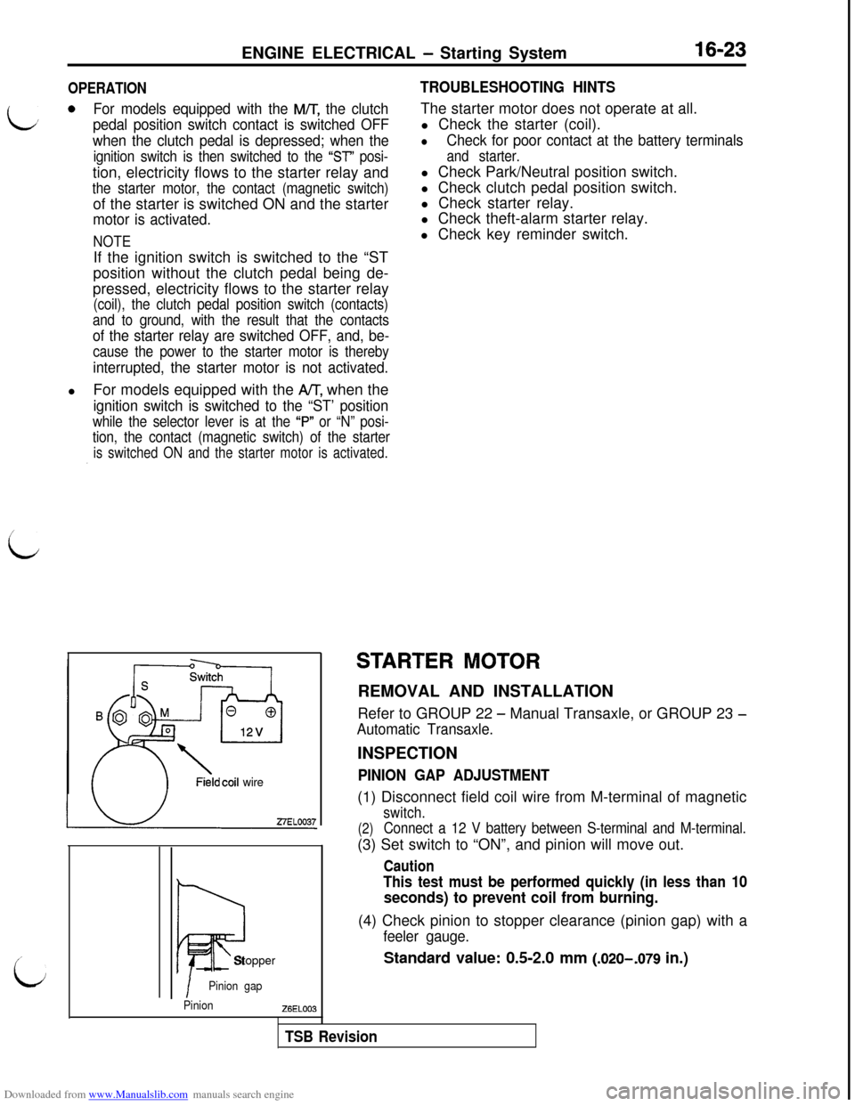
Fieldcoil wire
Iii?Stopper
IPinion gap
PinionZ6EL003
STARTER MOTORREMOVAL AND INSTALLATION
Refer to GROUP 22
- Manual Transaxle, or GROUP 23 -
Automatic Transaxle.INSPECTION
PINION GAP ADJUSTMENT(1) Disconnect field coil wire from M-terminal of magnetic
switch.
(2)Connect a 12 V battery between S-terminal and M-terminal.(3) Set switch to “ON”, and pinion will move out.
Caution
This test must be performed quickly (in less than 10
seconds) to prevent coil from burning.(4) Check pinion to stopper clearance (pinion gap) with a
feeler gauge.
Standard value: 0.5-2.0 mm (.020-,079 in.)
TSB Revision
Page 477 of 738
Downloaded from www.Manualslib.com manuals search engine i/ENGINE ELECTRICAL
- Ignition System
IGNITION SYSTEM
16-31
SPECIFICATIONSGENERAL SPECIFICATIONS
CRANK ANGLE SENSOR cup to 1992 model>
Items
Specifications
TypeContact pointless type
Identification No.
Tl T49371
Part No.MD1 53464
Advance mechanism
Firing orderControlled by engine control unitl-2-3-4-5-6
IGNITION COILrItems
Type
Identification No.SpecificationsMold 3-coil
F-536
L
IPart No.j MD152648I
SPARK PLUG
Items
NGK-Specifications
PFRGJ-11
NIPPON DENS0PK20PRPllSERVICE SPECIFICATIONS
Items
Ignition coilStandard valueLimit
Primary coil resistance at
20°C0.67-0.81(68°F)
RSecondary coil resistance at
11.3-15.3
20°C (68°F) kc2
Spark plug gap mm (in.)1.0-l .l (0.39-0.43)Spark plug cable
kQ
1.3 (.051)
Max. 22SPECIAL
TOOLS
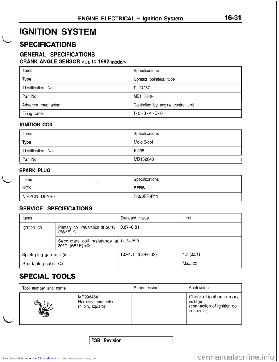
Tool number and nameSupersessionApplication
i
MD998464
Harness connector
(4 pin, square)Check of ignition primaryvoltage
(connection of ignition coil
connector)
i
TSB Revision
Page 499 of 738
Downloaded from www.Manualslib.com manuals search engine CHASSIS ELECTRICAL - Battery54-3
BATTERY
LSPECIFICATIONSGENERAL SPECIFICATIONS
ItemsUp to 1993 modelsFrom 1994 models
Type75D26R-MF75D23R-MF
Ampere hours
(5HR) Ah5252
Cranking rating [at -18°C (O’F)] A490520
Reserve capacity min.123118
NOTES
1.CRANKING RATING is the current a battery can deliver for 30 seconds and maintain a terminal voltage of
7.2 volts or greater at a specified temperature.
2.RESERVE CAPACITY RATING is the amount of time a battery can deliver 25A and maintain a minimum terminal
voltage of 10.5 at
27% (80°F).
L
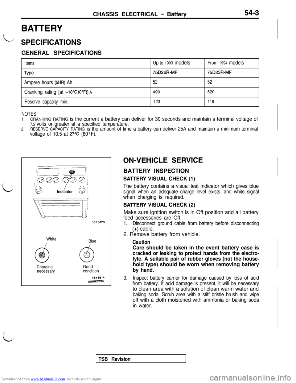
16FO123
White
Blue
ChargingGood
necessaryconditionON-VEHICLE
SERVICE
BATTERY INSPECTION
BAlTERY VISUAL CHECK (1)
The battery contains a visual test indicator which gives blue
signal when an adequate charge level exists, and white signal
when charging is required.
BAlTERY VISUAL CHECK (2)
Make sure ignition switch is in Off position and all battery
feed accessories are Off.
1.Disconnect ground cable from battery before disconnecting
(+) cable.
2. Remove battery from vehicle.
CautionCare should be taken in the event battery case is
cracked or leaking to protect hands from the electro-
lyte. A suitable pair of rubber gloves (not the house-hold type) should be worn when removing battery
by hand.
3.Inspect battery carrier for damage caused by loss of acid
from battery. If acid damage is present, it will be necessaryto clean area with a solution of clean warm water and
baking soda. Scrub area with a stiff bristle brush and wipe
off with a cloth moistened with ammonia or baking soda
in water.
TSB Revision
Page 560 of 738
Downloaded from www.Manualslib.com manuals search engine 54-64CHASSIS ELECTRICAL - Lighting System
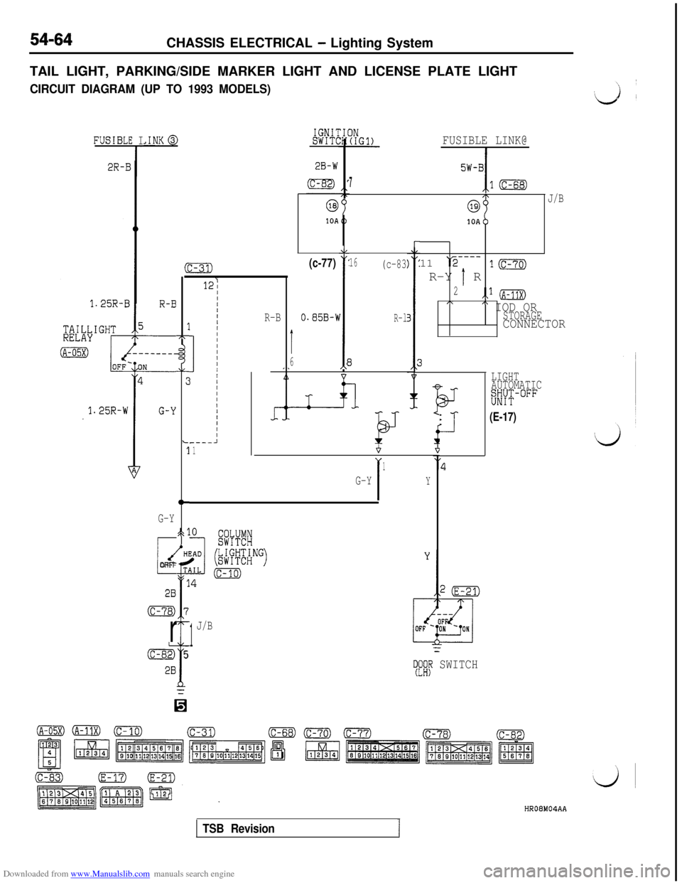
TAIL LIGHT, PARKING/SIDE MARKER LIGHT AND LICENSE PLATE LIGHT
CIRCUIT DIAGRAM (UP TO 1993 MODELS)
IGNIlSWIT(.INK@,E I
T
FUSIBLE LINK@
I
FUSIBL
2R-15W-BI
710
J/B
1OAb11
‘r2---_R-Y
1 R
1m
2.,* (A-11X),\" IOD ORSTORAGECONNECTOR
r
16(c-83(c-77)
1
O.S5B-1I
6E
A
kJ
R-l
3
fi
17r
AL
:c
3
tt-
523
Gi
T1
1
7
f
5
0
G-Y
i
dOFF
28
(c-78)
r
&
28
:-31)
12;
IIIIIIIIIIIIIIIIIII/IIII----A1
R-B
LIGHT
AUTOMATIC
%YT-°FF
I-
BJ-
*
i-l-.(E-17)
I
1
G-YY
1
J/B
=
TFi# SWITCH
HR08M04AA
TSB Revision1
Page 598 of 738
Downloaded from www.Manualslib.com manuals search engine CHASSIS ELECTRICAL - Lighting System
Up to 1993 modelsFrom 1994 mod&
__ _..--.
Vertical center lineZ16FO509
JHot
z&ky M-j’ Within~ Within600mm1mm (in.)600 mm
(23.6)
(23.6)
Note l ’ Up to 1993 modelsl 2 From 1994 models
1 Etomj
0000236600002387
LUMINOUS INTENSITY MEASUREMENT
Measure the luminous intensity of headlights with a photo-me-ter in accordance with the instruction manual prepared by
the manufacturer of the photometer and make sure that the
luminous intensity is within the following limit.Limit: 20,000 cd or more
NOTE
(1) When measuring the luminous intensity of headlight, keepthe engine at 2,000 rpm and have the battery charged.
(2) If there are specific regulations for luminous intensity ofheadlights in the region where the vehicle is operated,
make sure that the intensity conforms to the requirements
of such regulations.
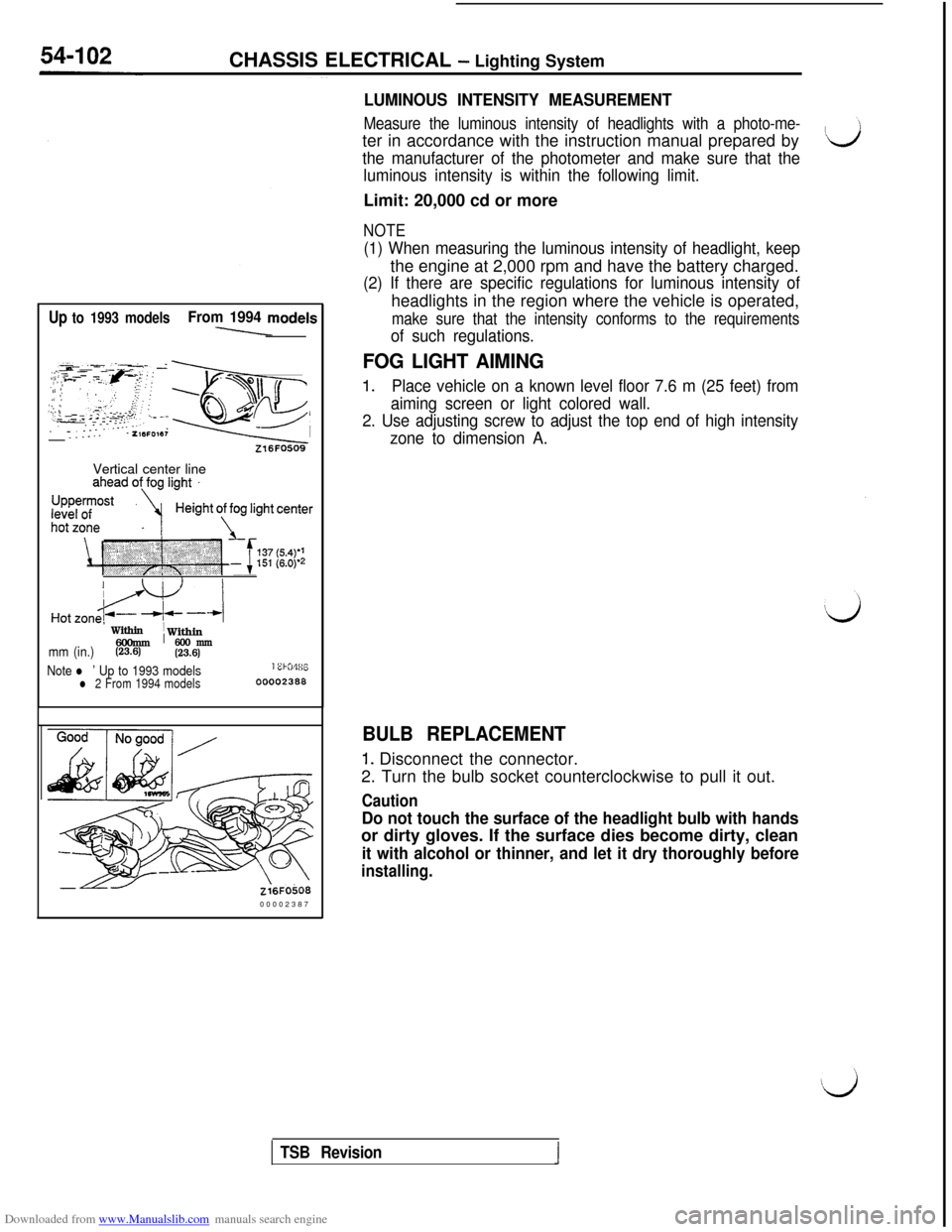
FOG LIGHT AIMING
1.Place vehicle on a known level floor 7.6 m (25 feet) from
aiming screen or light colored wall.
2. Use adjusting screw to adjust the top end of high intensity
zone to dimension A.
BULB REPLACEMENT
1. Disconnect the connector.
2. Turn the bulb socket counterclockwise to pull it out.
Caution
Do not touch the surface of the headlight bulb with handsor dirty gloves. If the surface dies become dirty, clean
it with alcohol or thinner, and let it dry thoroughly before
installing.
TSB Revision