fog light MITSUBISHI 3000GT 1992 2.G User Guide
[x] Cancel search | Manufacturer: MITSUBISHI, Model Year: 1992, Model line: 3000GT, Model: MITSUBISHI 3000GT 1992 2.GPages: 738, PDF Size: 35.06 MB
Page 47 of 738
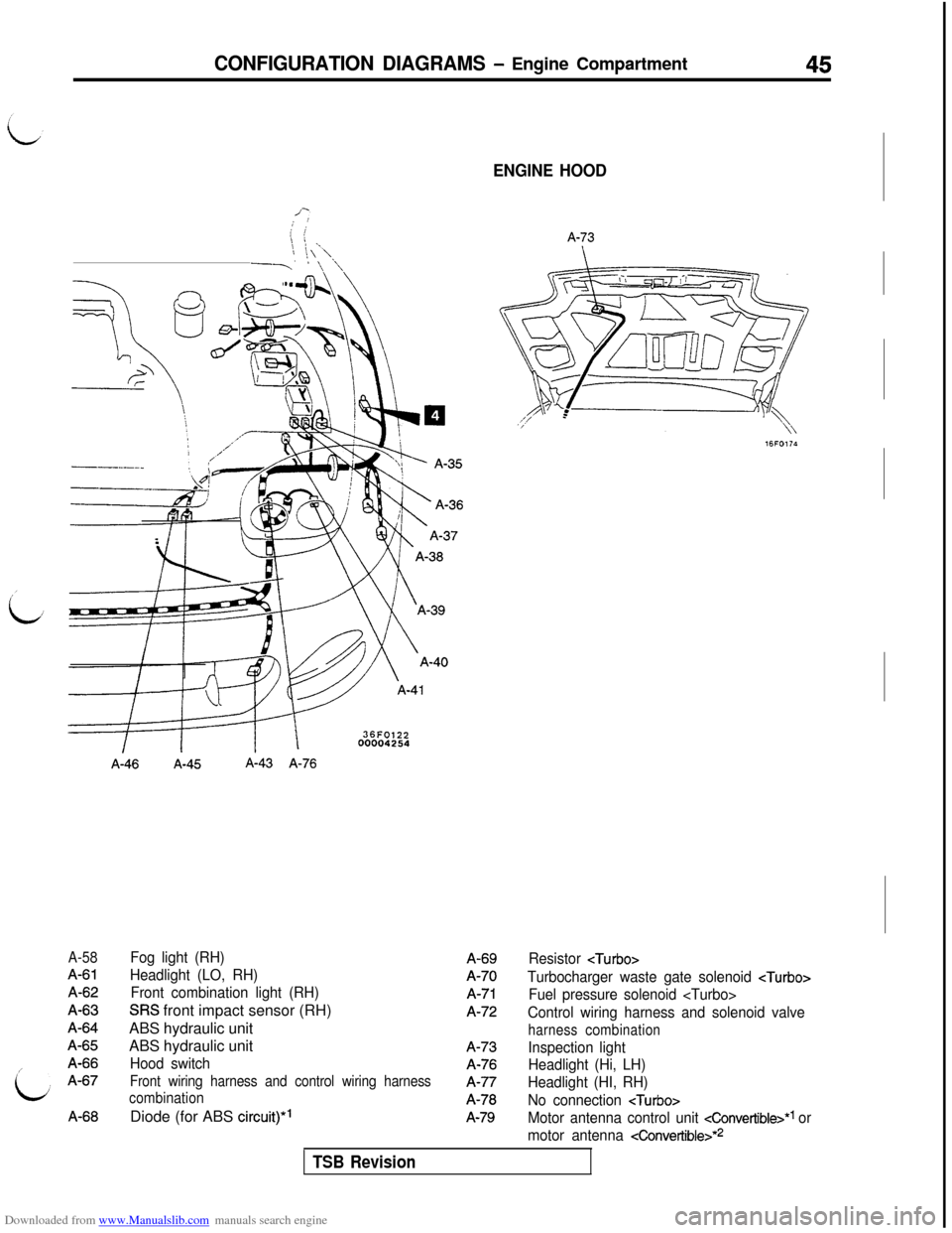
Downloaded from www.Manualslib.com manuals search engine CONFIGURATION DIAGRAMS - Engine Compartment45
; !i i\1 ._’ !\\-7’I \ ‘\
A-58
A-61A-62A-63A-64A-65A-66A-67A-66
A-46A-45A-43 A-76
Fog light (RH)
Headlight (LO, RH)
Front combination light (RH)
SRS front impact sensor (RH)
ABS hydraulic unit
ABS hydraulic unit
Hood switch
Front wiring harness and control wiring harness
combinationDiode (for ABS
circuit)*’
ENGINE HOOD
A-73A-69A-70
A-71A-72A-73A-76A-77A-78
A-79
Resistor
Turbocharger waste gate solenoid
Fuel pressure solenoid
Control wiring harness and solenoid valve
harness combination
Inspection light
Headlight (Hi, LH)
Headlight (HI, RH)
No connection
Motor antenna control unit cConvertible>*1 or
motor antenna
4onvertible>*2
TSB Revision
Page 52 of 738
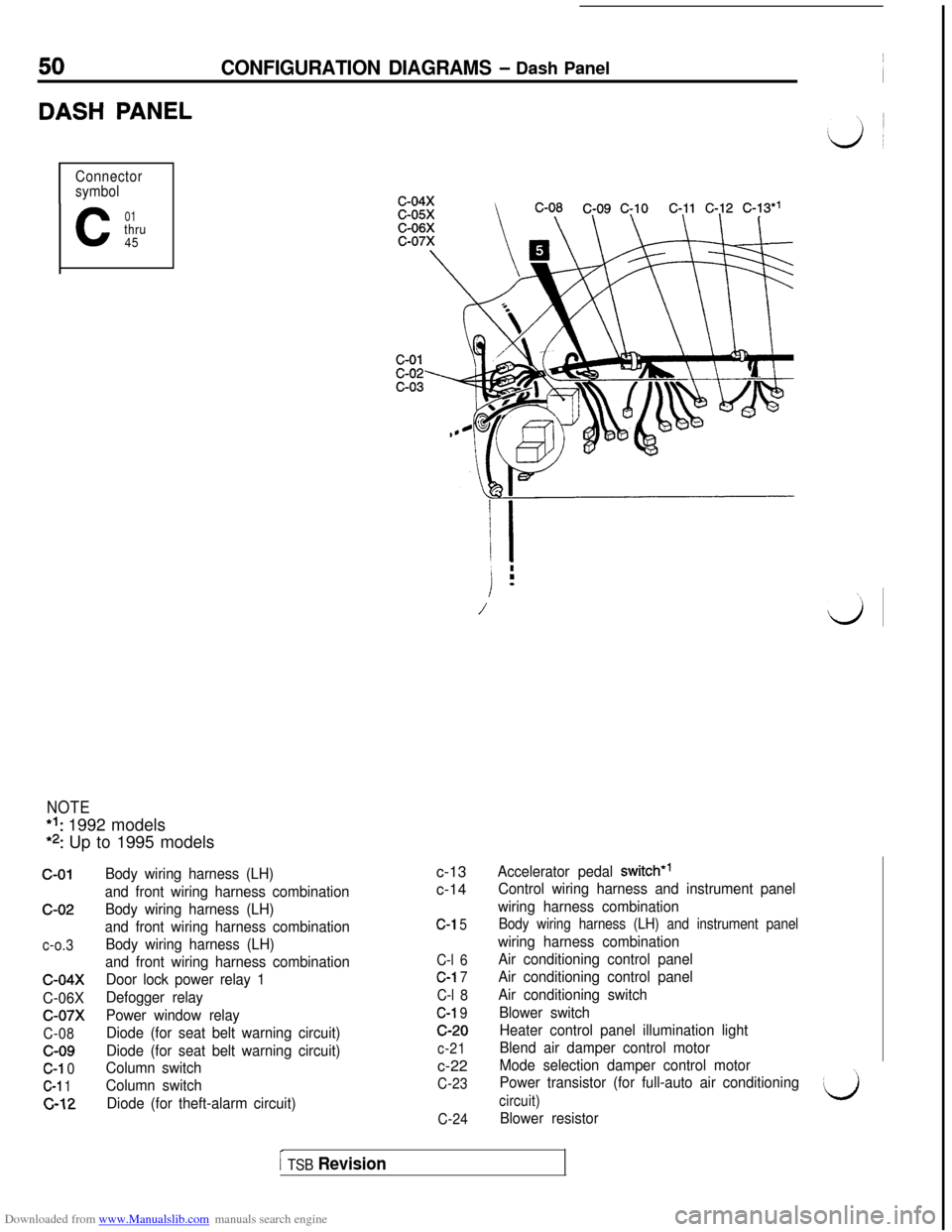
Downloaded from www.Manualslib.com manuals search engine 50CONFIGURATION DIAGRAMS - Dash Panel
DASH PANEL
Connector
symbol
C
01thru
45
NOTE*I: 1992 models
*2: Up to 1995 models
c-01c-02
c-o.3
c-04x
C-06X
c-07x
C-08c-09
C-l 0
C-l 1
c-12
Body wiring harness (LH)
and front wiring harness combination
Body wiring harness (LH)
and front wiring harness combination
Body wiring harness (LH)
and front wiring harness combination
Door lock power relay 1
Defogger relay
Power window relay
Diode (for seat belt warning circuit)
Diode (for seat belt warning circuit)
Column switch
Column switch
Diode (for theft-alarm circuit)c-13
c-14
C-l 5
C-l 6
C-l 7
C-l 8
C-l 9c-20
c-21c-22
C-23
C-24
/ i
i
.m
/\\
LJ
Accelerator pedal switch*’
Control wiring harness and instrument panel
wiring harness combination
Body wiring harness (LH) and instrument panel
wiring harness combination
Air conditioning control panel
Air conditioning control panel
Air conditioning switch
Blower switch
Heater control panel illumination light
Blend air damper control motor
Mode selection damper control motor
Power transistor (for full-auto air conditioning
circuit)
Blower resistor
I TSB Revision
Page 56 of 738
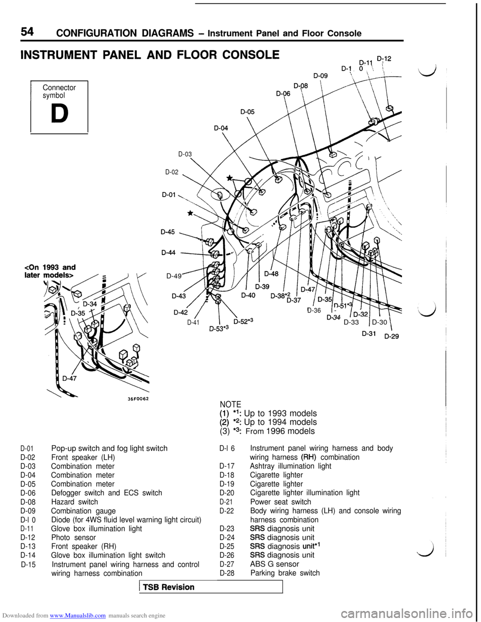
Downloaded from www.Manualslib.com manuals search engine 54CONFIGURATION DIAGRAMS - Instrument Panel and Floor Console
INSTRUMENT PANEL AND FLOOR CONSOLED-11 D;‘2D-1 0 ‘.,, \
I
Connectorsymbol
D
1993 and
D-03
D-Or ~~\\ Id&
D-02
4D-49 _
D-4i /
D-41
D-36I- -’rL?A/D-:” “- D-331 D-30“-c.w -\D-31 D-29
D-01
D-02
D-03
D-04
D-05
D-06
D-08
D-09
D-l 0
D-11
D-12
D-13
D-14
D-15Pop-up switch and fog light switch
Front speaker (LH)
Combination meter
Combination meter
Combination meter
Defogger switch and ECS switch
Hazard switch
Combination gauge
Diode (for 4WS fluid level warning light circuit)
Glove box illumination light
Photo sensor
Front speaker (RH)
Glove box illumination light switch
Instrument panel wiring harness and control
wiring harness combination
1 TSB Revision
NOTE
I:I*l: Up to 1993 models*? Up to 1994 models
(3)
*3:From 1996 models
D-l 6
D-17
D-18
D-19
D-20
D-21
D-22
D-23
D-24
D-25
D-26
D-27
D-28
Instrument panel wiring harness and body
wiring harness
(RH) combination
Ashtray illumination light
Cigarette lighter
Cigarette lighter
Cigarette lighter illumination light
Power seat switch
Body wiring harness (LH) and console wiring
harness combination
SRS diagnosis unit
SRS diagnosis unit
SRS diagnosis unit*’
SRS diagnosis unit
ABS G sensor
Parking brake switch
Page 60 of 738
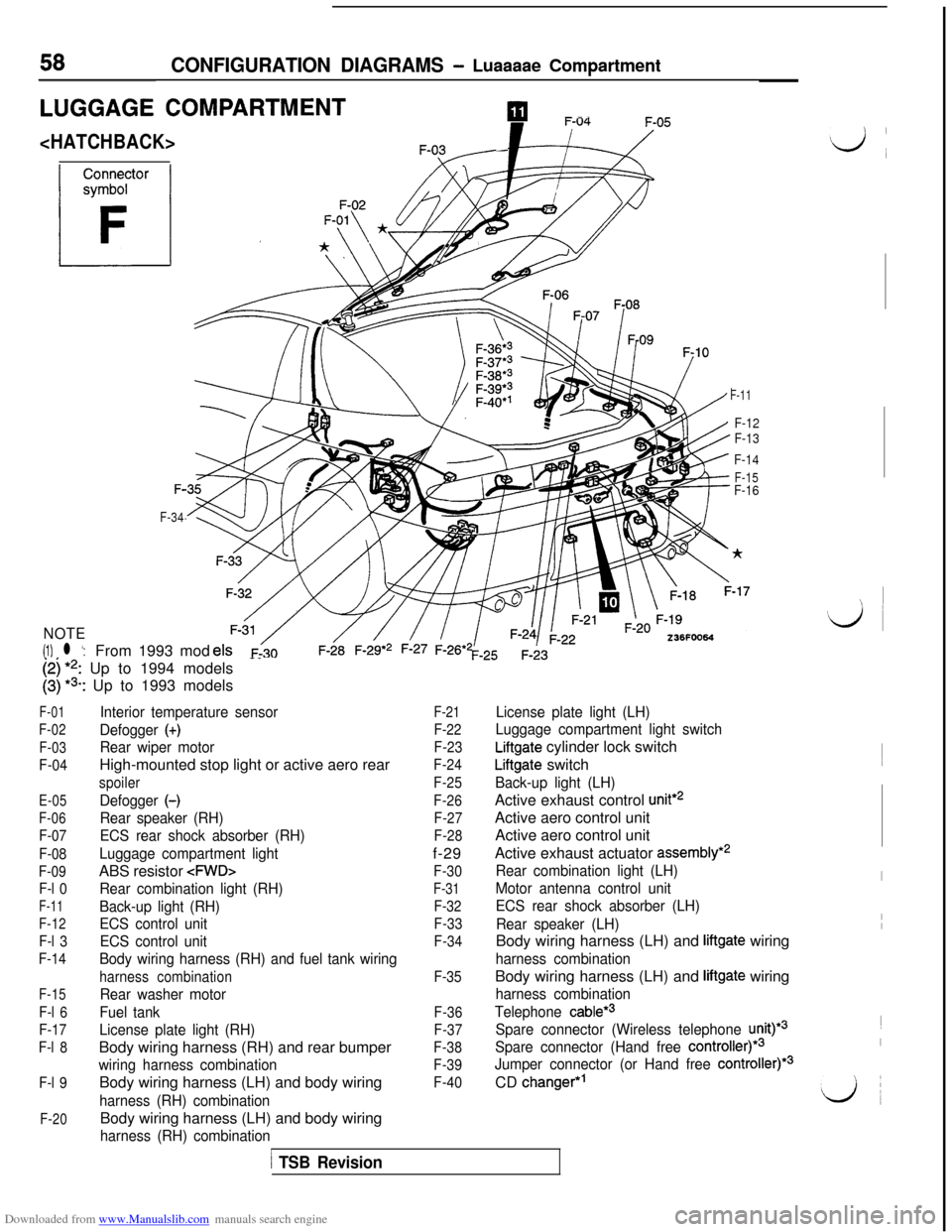
Downloaded from www.Manualslib.com manuals search engine 58CONFIGURATION DIAGRAMS - Luaaaae Compartment
LUGGAGE COMPARTMENTpIl --.
F-11
F-12
F-13
F-14
F-15F-F-16
F-34
NOTE
(1) l ‘:From 1993 mod
[;I I’,: Up to 1994 models-_
: Up to 1993 models
F-01
F-02
F-03
F-04
E-05
F-06
F-07
F-08
F-09
F-l 0
F-11
F-12
F-l 3
F-14
F-15
F-l 6
F-17
F-l 8
F-l 9
F-20
Interior temperature sensor
Defogger
(+)
Rear wiper motorHigh-mounted stop light or active aero rear
spoiler
Defogger (-)
Rear speaker (RH)
ECS rear shock absorber (RH)
Luggage compartment lightABS resistor
Rear combination light (RH)
Back-up light (RH)
ECS control unit
ECS control unit
Body wiring harness (RH) and fuel tank wiring
harness combination
Rear washer motor
Fuel tank
License plate light (RH)Body wiring harness (RH) and rear bumper
wiring harness combinationBody wiring harness (LH) and body wiring
harness (RH) combinationBody wiring harness (LH) and body wiring
harness (RH) combination
F-21
F-22
F-23
F-24
F-25
F-26
F-27
F-28f-29
F-30
F-31
F-32
F-33
F-34
F-35
F-36
F-37
F-38
F-39
F-40
License plate light (LH)
Luggage compartment light switch
Liftgate cylinder lock switch
Liftgate switch
Back-up light (LH)Active exhaust control
unit*2Active aero control unit
Active aero control unit
Active exhaust actuator
assembly*2
Rear combination light (LH)
Motor antenna control unit
ECS rear shock absorber (LH)
Rear speaker (LH)Body wiring harness (LH) and
liftgate wiring
harness combinationBody wiring harness (LH) and
liftgate wiring
harness combination
Telephone
cable*3
Spare connector (Wireless telephone unity3
Spare connector (Hand free
controller)*3
Jumper connector (or Hand free controller)*3CD
changer*’
1 TSB Revision
I
‘id ~~
I
II~
I
LJ
Page 61 of 738
Downloaded from www.Manualslib.com manuals search engine CONFIGURATION DIAGRAMS.- Luggage Compartment
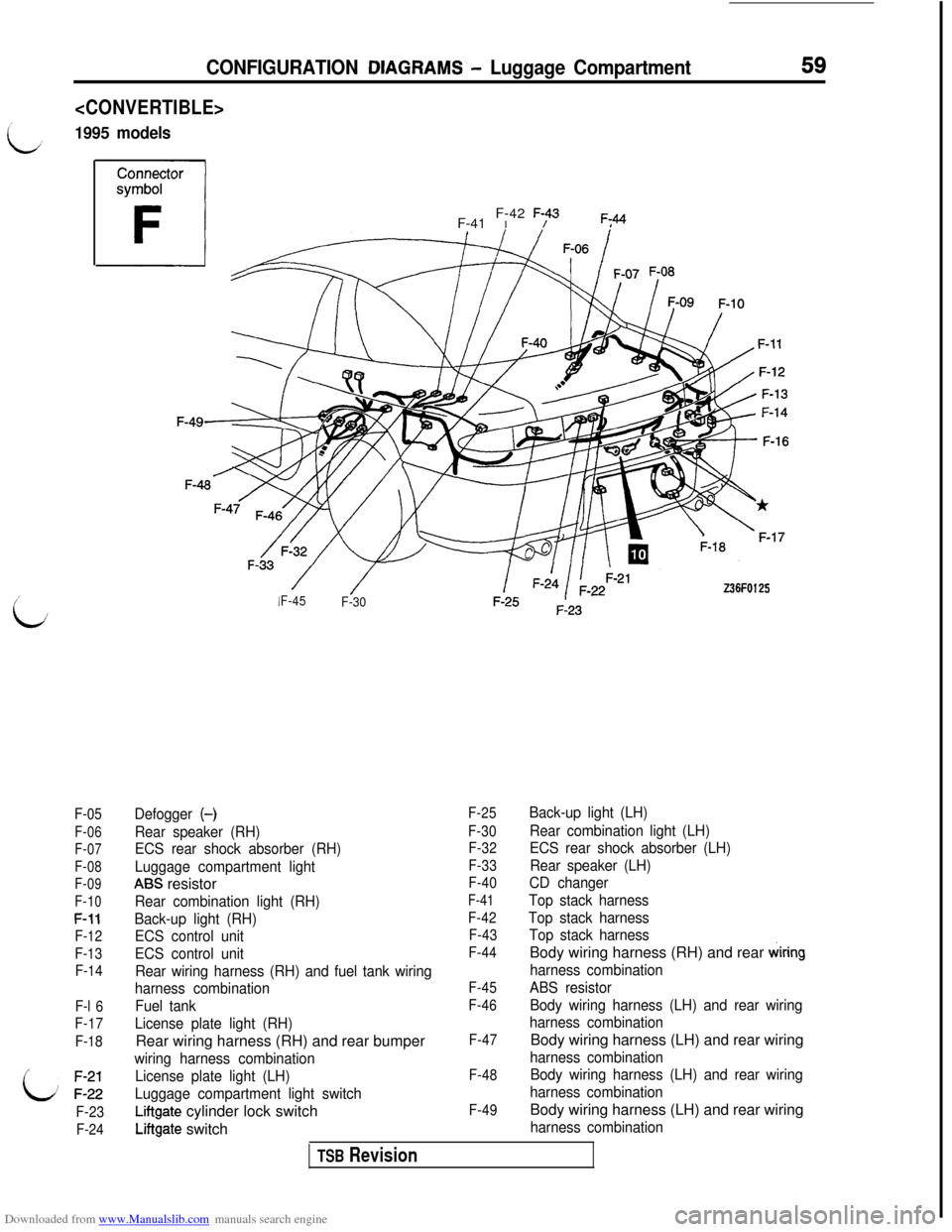
1995 models
59
/
iJ
F-05
F-06
F-07
F-08
F-09
F-10
F-11
F-12
F-13
F-14
F-l 6
F-17
F-18
i: ;:;;
F-23
F-24F-41 I F-42
F;43F;44
Z36FO125F-45
F-30
Defogger (-)
Rear speaker (RH)
ECS rear shock absorber (RH)
Luggage compartment light
ABS resistor
Rear combination light (RH)
Back-up light (RH)
ECS control unit
ECS control unit
Rear wiring harness (RH) and fuel tank wiring
harness combination
Fuel tank
License plate light (RH)Rear wiring harness (RH) and rear bumper
wiring harness combination
License plate light (LH)
Luggage compartment light switch
Liftgate cylinder lock switch
Liftgate switch
F-25
F-30
F-32
F-33
F-40
F-41
F-42
F-43
F-44
F-45
F-46
F-47
F-48
F-49
Back-up light (LH)
Rear combination light (LH)
ECS rear shock absorber (LH)
Rear speaker (LH)
CD changer
Top stack harness
Top stack harness
Top stack harnessBody wiring harness (RH) and rear
wiring
harness combination
ABS resistor
Body wiring harness (LH) and rear wiring
harness combinationBody wiring harness (LH) and rear wiring
harness combination
Body wiring harness (LH) and rear wiring
harness combinationBody wiring harness (LH) and rear wiring
harness combination
TSB Revision
Page 63 of 738
Downloaded from www.Manualslib.com manuals search engine 61
i
CIRCUIT
DlAG.RAMS
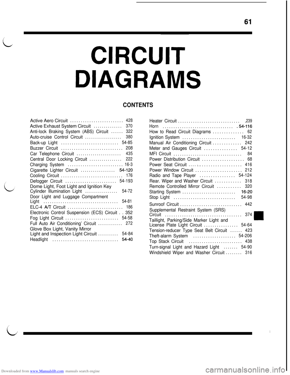
CONTENTSActive Aero Circuit.........................
428Active Exhaust System Circuit..............
370
Anti-lock Braking System (ABS) Circuit......322
Auto-cruise Control Circuit..................380
Back-up Light...........................54-85
Buzzer Circuit.............................208
Car Telephone Circuit......................435
Central Door Locking Circuit................222
Charging System..........................16-3
Cigarette Lighter Circuit.................54-120
Cooling Circuit.............................176
Defogger Circuit........................54-193Dome Light, Foot Light and Ignition Key
Cylinder Illumination Light................54-72
Door Light and Luggage Compartment
Light...................................54-81
ELC-4 A/T Circuit..........................186
Electronic Control Suspension (ECS) Circuit . . 352
Fog Light Circuit.........................
54-58
Full Auto Air Conditioning’ Circuit............272Glove Box Light, Vanity Mirror
Light and Inspection Light Circuit..........
54-84
Headlight...............................
54-40
Heater Circuit.............................,239
Horn..................................54-116
How to Read Circuit Diagrams..............
62
Ignition System.........................16-32
Manual Air Conditioning Circuit.............242
Meter and Gauges Circuit...............54-12
MFI Circuit................................84
Power Distribution Circuit...................68
Power Seat Circuit....:...................416
Power Window Circuit.....................212
Radio and Tape Player................54-124
Rear. Wiper and Washer Circuit............318
Remote Controlled Mirror Circuit...........320
Starting System.........................16-20
Stop Light.............................54-98
Sunroof Circuit.............................442
Supplemental Restraint System (SRS)
Circuit....................................374
Taillight, Parking/Side Marker Light and
License Plate Light Circuit................54-64
Tension-reducer Type Seat Belt Circuit......423
Theft-alarm System....................54-206
Top Stack Circuit.........................438
Turn-signal Light and Hazard Light.......54-90
Windshield Wiper and Washer Circuit........316
I
LiI
Page 71 of 738
Downloaded from www.Manualslib.com manuals search engine CIRCUIT DIAGRAMS - Power Distribution Circuit69
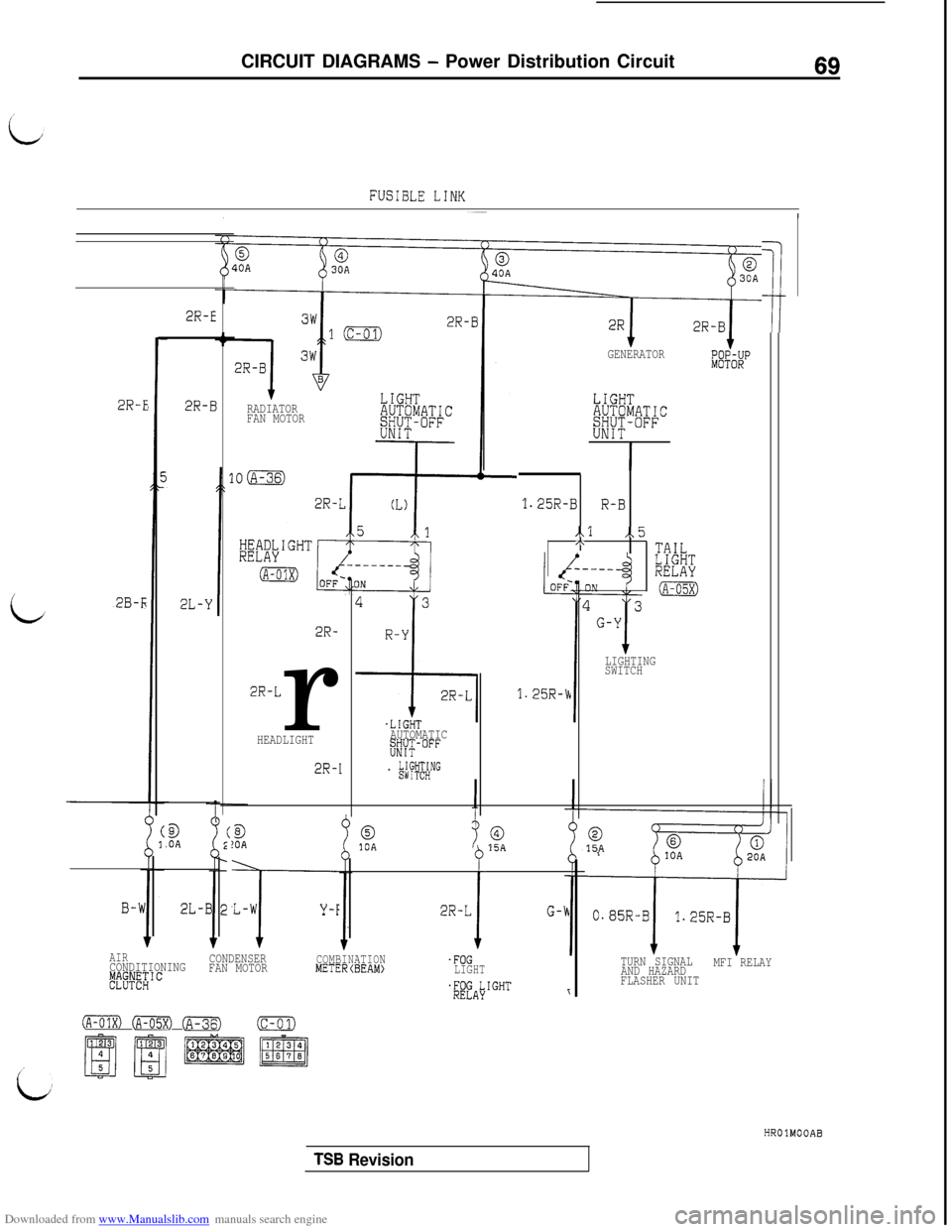
FUSIBLE LINK
/
i
2R-E
2B-r;
c9
.OAB!OA0,10A015A
B-W'L-W
T
Y-F2R-L
i
G-k2L-B
2R-E
2R-BRADIATOR
FAN MOTOR
2R-
2R-Lr
HEADLIGHT
2R-I
.LIGHTAUTOMATIC;#JT-OFF
. #;HNG
1;
1.25R-Cc
GENERATORE&RUP
LIGHTAUTOMATIC&#~+-oFF
I
1.25R-BR-B
..l,.5ATAILLIGHTRELAY
(A-05X)
LIGHTING
SWITCH
AIRCONDITIONINGCONDENSER#~T"~~ICFAN MOTOR
COMBINATIONMETERCBEAM).FOGLIGHT
$"fALyIGHTr
IA-01x) (A-05X) @iqJ(c-01)
015A
TURN SIGNAL
AND HAZARDMFI RELAY
FLASHER UNITHROlMOOAB
TSB Revision
Page 75 of 738
Downloaded from www.Manualslib.com manuals search engine CIRCUIT DIAGRAMS - Power Distribution Circuit73
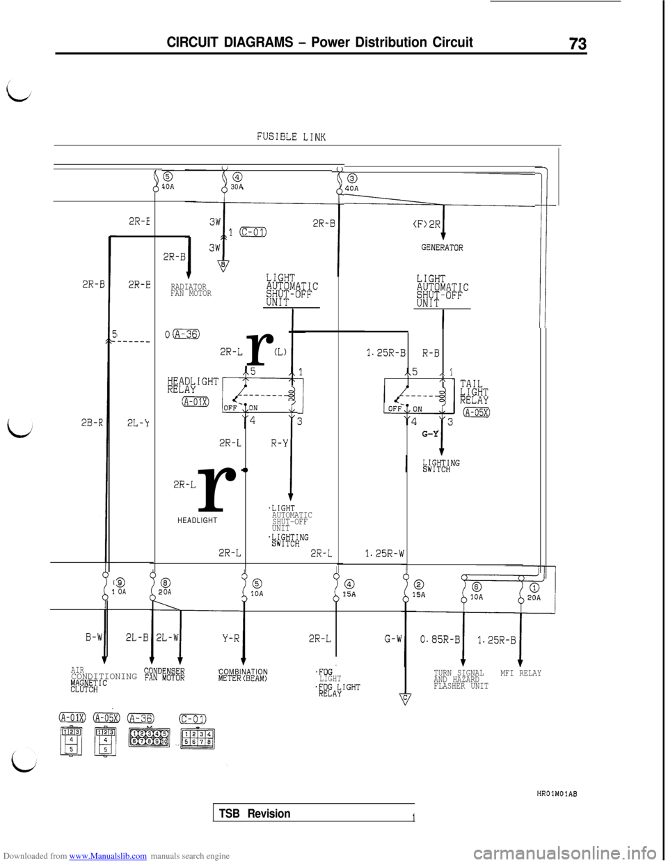
FUSIBLE LINK
-
@
ii
030A
40A
";1
$OA
LIGHTRADIATOR
FAN MOTORAUTOMATIC&-$;-OFF
0m
2R-Lr(L)ON
4
2R-LR-k
41
2R-Lr
HEADLIGHT
2R-L
i.LIGHTAUTOMATIC
SHUT-OFF
UNIT
.&FT"gHNG
2R-L
2R-E
2R-B
LIGHTAUTOMATIC&{Yi-l-OFF
I
2R-f
2B-I
2R-E
I-----_
2L-k
9OA
B-W2L-B
AIRCONDITIONING F;p!E$IC
1.25R-BR-B
,.5,\ 1/\ -
G-Y
1.25R-Cv
010AaOA015A
TURN SIGNAL
AND HAZARDMFI RELAY
FLASHER UNIT
2R-LG-WCOMBINATION
METERCBEAM).FOG.LIGHTQfAi+GHT\i7C
HROlMOlAB
TSB Revision1
Page 79 of 738
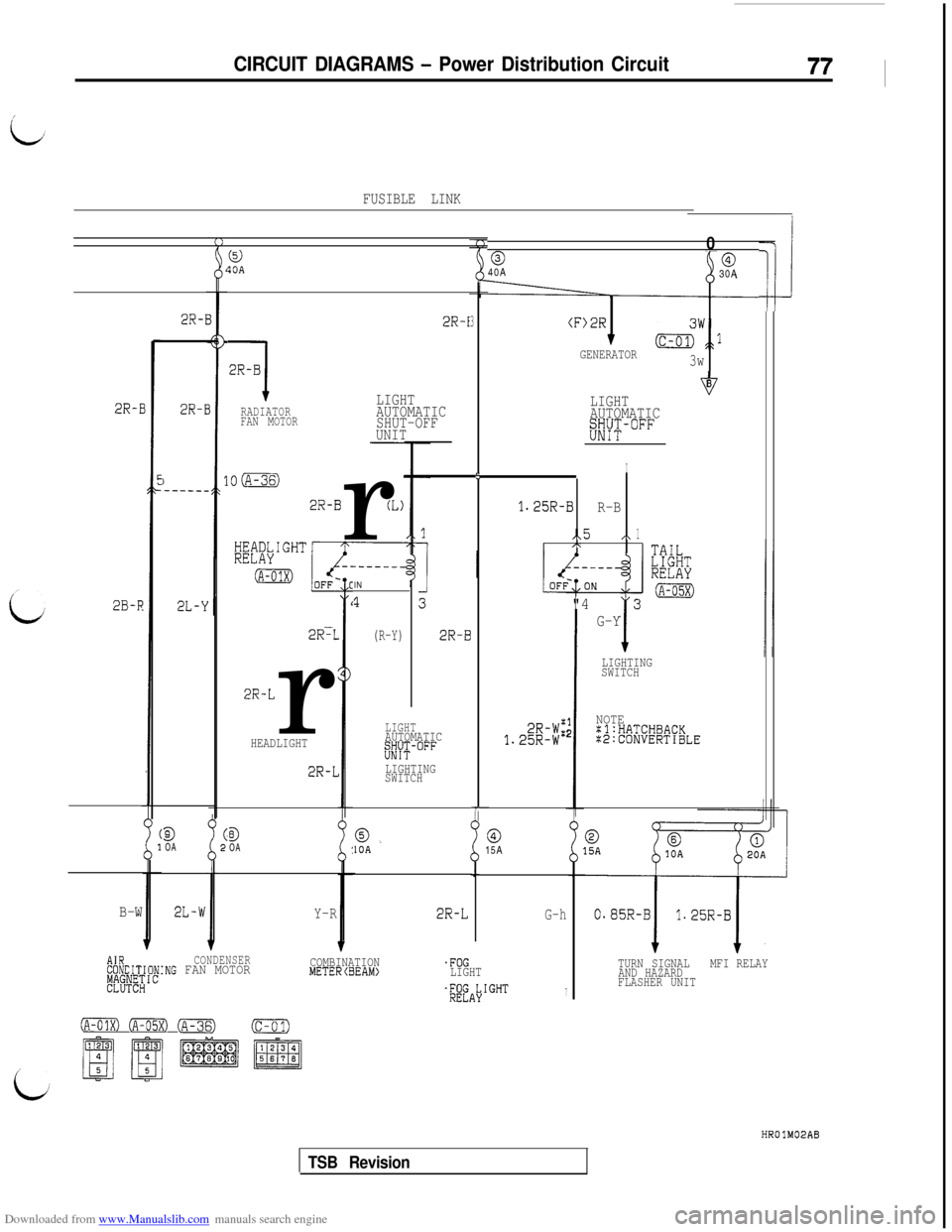
Downloaded from www.Manualslib.com manuals search engine CIRCUIT DIAGRAMS - Power Distribution Circuit77I
FUSIBLE LINK
1!
0
0040A
30A
(F)2R
TGENERATOR&w,:l
3w
@ISOA
2R-I2R-l
1
2R-B
LIGHTRADIATOR
FAN MOTORAUTOMATIC
SHUT-OFF
UNIT
3
6B
LIGHT
AUTOMATIC
WT-"""
I5
1.25R-BR-B
..5,\1C\
/
"4
12
-
G-Y
LIGHTING
SWITCH
NOTE:l:HATCHBACK:E:CONVERTIBLE
2R-I
2B-F
2R-E
)-----_
3OA
2R-Br(L)
5
2R-BIN
1
(R-Y)2R-L
2R-Lr
LIGHTAUTOMATIC
f%YT-""' HEADLIGHT
2R-LLIGHTING
SWITCH
i3OA015A0.IOA
B-WY-R2R-LG-h
CONDENSER~%DITIONING FAN MOTORCOMBINATIONMETERlBEAM).FOG
p~.w~;IcLIGHT.;'fA\'GHT7
TURN SIGNALMFI RELAY
AND HAZARD
FLASHER UNIT
0 (A-05X) (A-36)Ic-ol)
TSB Revision
Page 83 of 738
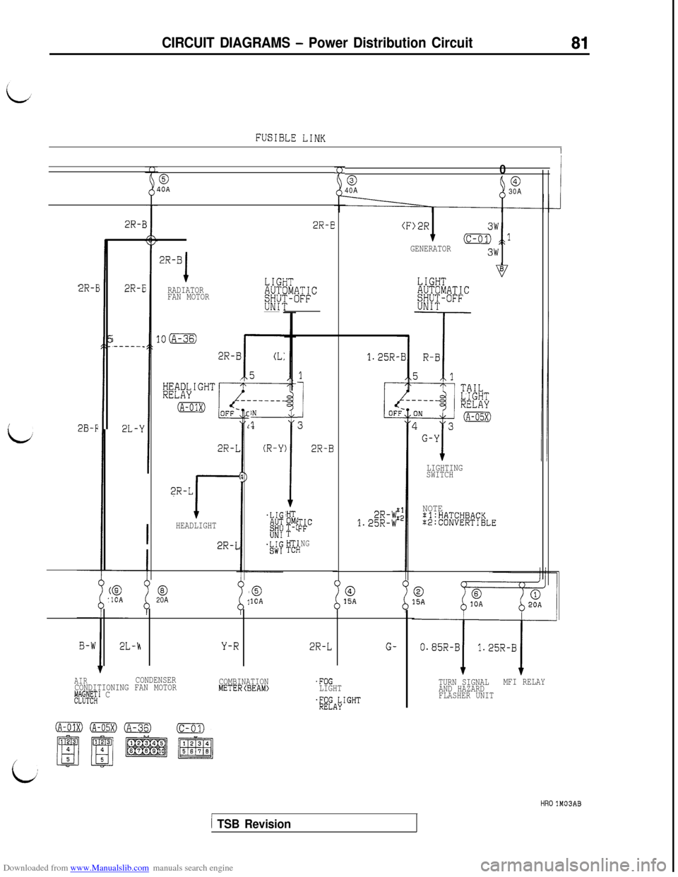
Downloaded from www.Manualslib.com manuals search engine CIRCUIT DIAGRAMS - Power Distribution Circuit81
FUSIBLE LINK
I
0
0040A
30A
(F>2R
7GENERATOR&wJ
3w
0?OA
2R-E2R-E
2R-B
1RADIATOR
FAN MOTORLIGHTv
AUTOMATICSHUT-OFFUNIT
2R-r
2B-F
2R-F
i-----_
@10A
10m
2R-B
r
CL:
51
I
3
2R-B
NG1
1.25R.
2R-W1.25R-W
1N
1
(R-Y)
I!HTOMI:$-C
HTITCb
2R-L
?R-L
I-HEADLIGHT
2R-L
LIGHTING
SWITCH
NOTE=l:HATCHBACK:2:CONVERTIBLE
@20A010A015A
Y-R2R-LG-
AIRCONDENSER
CONDITIONING FAN MOTORCOMBINATION'FOG
ggI"c;1 CMETERCBEAM)LIGHT
$fAbIGHT
TURN SIGNAL
AND HAZARDMFI RELAY
FLASHER UNIT
HRO lM03AB
1 TSB Revision