lights MITSUBISHI 3000GT 1992 2.G User Guide
[x] Cancel search | Manufacturer: MITSUBISHI, Model Year: 1992, Model line: 3000GT, Model: MITSUBISHI 3000GT 1992 2.GPages: 738, PDF Size: 35.06 MB
Page 345 of 738
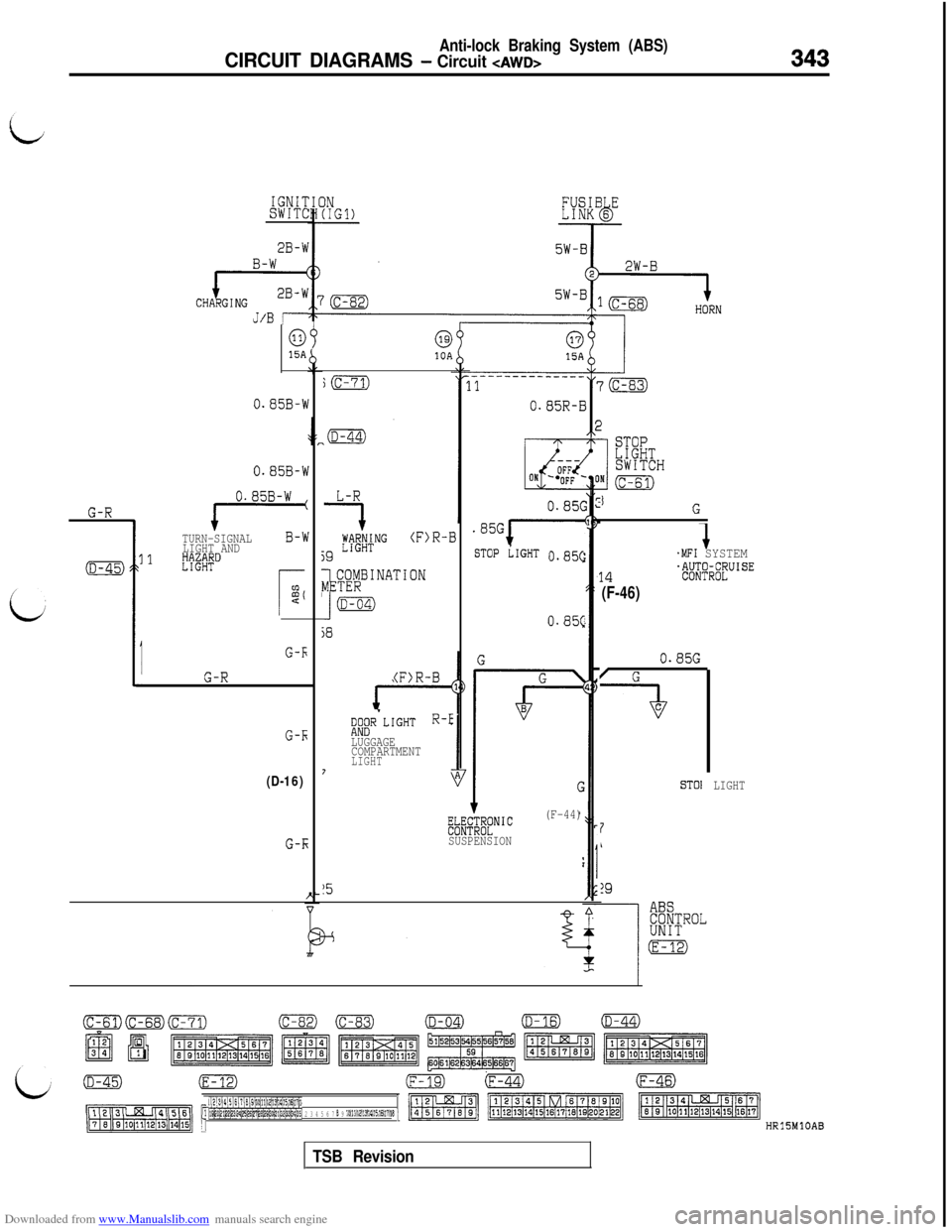
Downloaded from www.Manualslib.com manuals search engine Anti-lock Braking System (ABS)
CIRCUIT DIAGRAMS - Circuit CAWDB343
G-R
(D-45)3
I
IGNITSWITC
J/B r
0915A
0.85B-W
0.85B-W
TURN-SIGNALB-WLIGHT AND1E%TRD
G-k
G-R
G-Ii
(D-16)
G-E
j(c-71)
L-R
7
3KNG(F)R-B
59
I
COMBINATIONMETER
(D-d4)
93
(F)R-B
Do;R'LIGHT R-E
LUGGAGE
COMPARTMENT
LIGHT7
0.85G
.85Gi-'
STOP LIGHT O-85(
0.85(
Fb"NFLE;fNIC(F-44)
SUSPENSION
15
STOPLIGHTSWITCH
(c-61)
jG
.MFI SYSTEM
14.W;WiS;UISE
(F-46)
0.85G
/ G
-aC
ST01LIGHT
7/
!9
ABSCONTROLUNIT
(E-12)
cm(c-68)(c-71)o(c-83)(D-04)
~~ fiTimzmmm1
(D-16)(D-44)
fzEEi!g~~
(D-45)(E-12)(F-19)(F-44)(F-46)
-1p J~o,~l,2’2d3:214,~5~6~~,~*~91~o~l~2~3~41~5, 2 3 4 5 6 7 B 9 101112131415161716 ‘1ml/I:1f3mEaRjlHRlSMlOAB
TSB Revision
Page 349 of 738
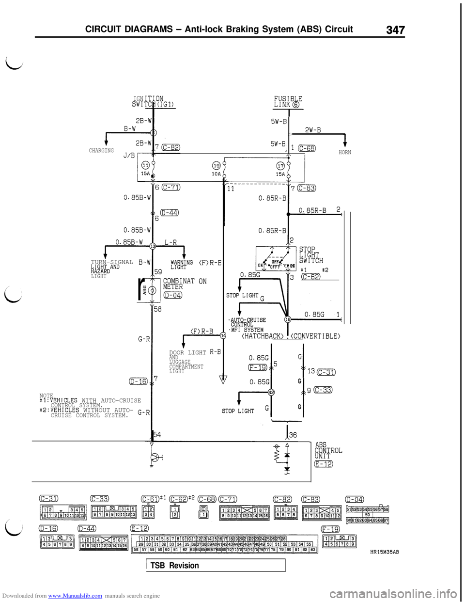
Downloaded from www.Manualslib.com manuals search engine CIRCUIT DIAGRAMS - Anti-lock Braking System (ABS) Circuit347
IGNSWI'
2B.
B-W
CHARGINGJ/B
o.a5B-
0.85B-
0.85B-W
TURN-SIGNAL B-h;$aI;DAND
LIGHT
r
:c
G-
NOTE:l:VEHICLES WITH AUTO-CRUISECONTROL SYSTEM.Z2:VEHICLES WITHOUT AUTO- G-CRUISE CONTROL SYSTEM.
i
-W
i:
-W
i
13
-W
E
i
E
.R
I
3 'i
R
5W-B
2)2W-B
51-B, 1 (c-68)HORN
L-R
j9
~H?l?~NG
I
COMBINATMETER
(D-04)
ia
(F)R-E
ON
DOOR LIGHT R-BAND
LUGGAGE
COMPARTMENTLIGHT
I
E54
O.a5R-BI
2
---
3
OFFON -'OFF - ON
0.85G
n3
STOPLIGHTSWITCH
:1:2(c-61)FE)
0.85GG
1 I
o5130
G
t
g(c-33)
G
- ABSCONTROLUNIT
(E-12)
HR15M35AB
1 TSB Revision
Page 433 of 738
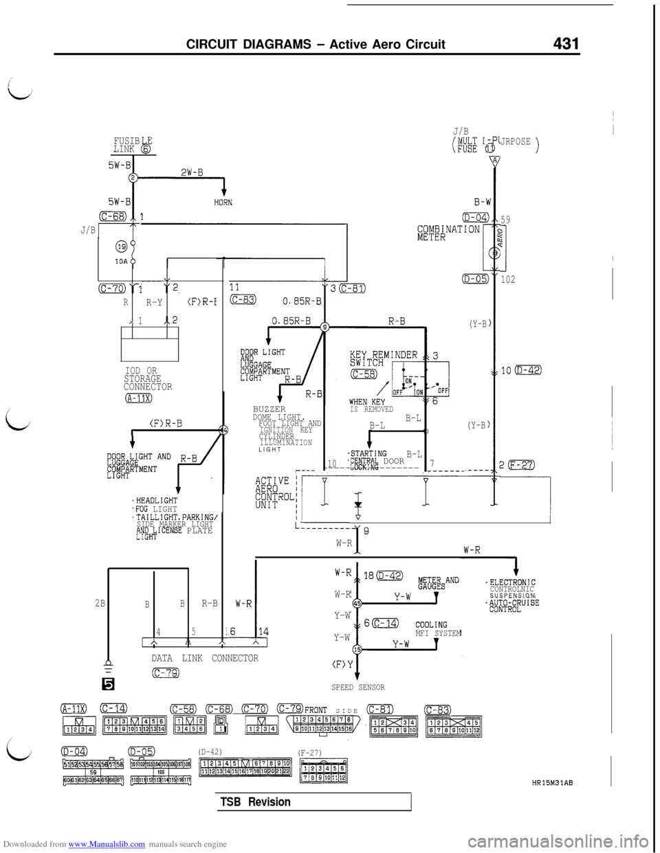
Downloaded from www.Manualslib.com manuals search engine CIRCUIT DIAGRAMS - Active Aero Circuit431
FUSIB E
LINK 6b
J/B
i
@
10A
\,----(c-70)‘1 “2.
RR-Y(F)R-I
,\ 1,.2
IOD ORSTORAGE
CONNECTOR
(F)R-Br
'HEADLIGHT.FOG LIGHT'TAILLIGHTsPARKING,SIDE MARKER LIGHTtjW&ICENSE PLATE
J/B
(WE 'e
BUZZERIS REMOVEDDOME LIGHT.FOOT LIGHT ANDB-L
IGNITION KEYB-LCYLINDER10ILLUMINATIONLIGHT
.STARTINGB-L10jf#Pf~~ DOOR7r--- ----------------------_-
(Y-B
(Y-B
JRPOSE)
59
?jc
I
102
20
-----I/
LL--------19W-R1
.
I.ELECTRONIC
CONTROLNICSUSPENSION
W-R
Y-W
Y-W
MFI SYSTEM
2BBBR-B
451AA*
nDATA LINK CONNECTOR(F>Y
n
(c-79)
SPEED SENSOR
(A-11X)0(c-58) (c-68) 0773 OFRONT SIDE (c-81)(c-83)
(D-42)
(F-27)
HR15M31AB
TSB Revision
Page 453 of 738
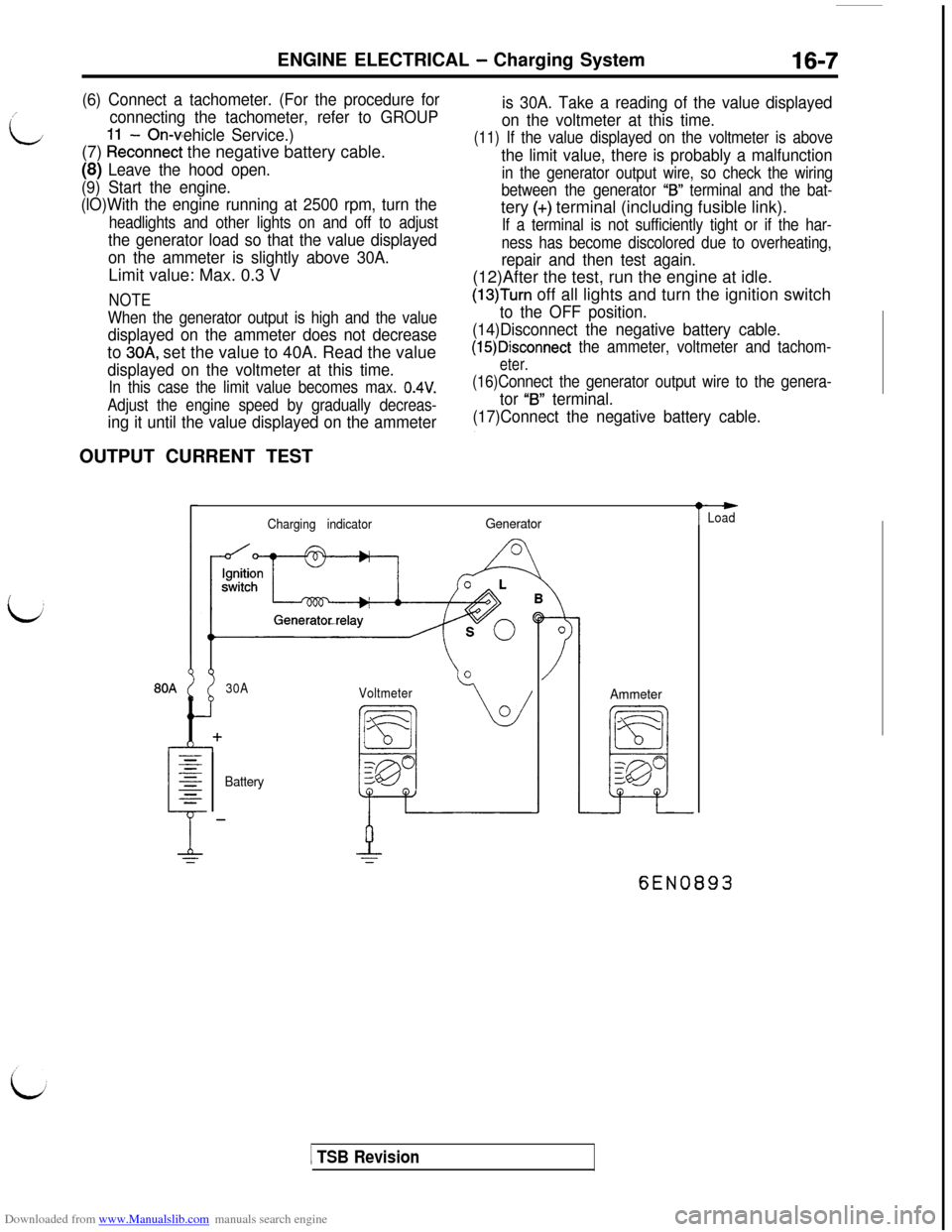
Downloaded from www.Manualslib.com manuals search engine ENGINE ELECTRICAL - Charging System16-7/
L
(6) Connect a tachometer. (For the procedure for
connecting the tachometer, refer to GROUP
- On-vehicle Service.)(7)
kkconnect the negative battery cable.
(8) Leave the hood open.
(9) Start the engine.
(lO)With the engine running at 2500 rpm, turn the
headlights and other lights on and off to adjust
the generator load so that the value displayed
on the ammeter is slightly above 30A.Limit value: Max. 0.3 V
NOTE
When the generator output is high and the value
displayed on the ammeter does not decreaseto
30A, set the value to 40A. Read the value
displayed on the voltmeter at this time.
In this case the limit value becomes max. 0.4V.
Adjust the engine speed by gradually decreas-
ing it until the value displayed on the ammeterOUTPUT CURRENT TEST
is 30A. Take a reading of the value displayed
on the voltmeter at this time.
(11) If the value displayed on the voltmeter is above
the limit value, there is probably a malfunction
in the generator output wire, so check the wiring
between the generator
“IS” terminal and the bat-tery
(+) terminal (including fusible link).
If a terminal is not sufficiently tight or if the har-
ness has become discolored due to overheating,
repair and then test again.(12)After the test, run the engine at idle.
(13)Turn off all lights and turn the ignition switch
to the OFF position.
(14)Disconnect the negative battery cable.
(15)Disconnect the ammeter, voltmeter and tachom-
eter.
(16)Connect the generator output wire to the genera-
tor “B” terminal.
(17)Connect the negative battery cable.
Charging indicatorGenerator
30A
Voltmeter
BatteryAmmeter
t
-Load
6EN0893
1 TSB Revision
Page 454 of 738
Downloaded from www.Manualslib.com manuals search engine 16-8ENGINE ELECTRICAL - Charging System
This test determines whether the generator outputs
normal current.(1) Before the test, always be sure to check the
following.l Generator installation
l
Battery (Refer to GROUP 54 - Battery.)
NOTE
The battery to be used should be slightly dis-charged. The load in a fully-charged battery
will be insufficient and the test may not be able
to be carried out correctly.l Generator drive belt tension (Refer to
GROUP 11- On-vehicle Service.)l Fusible link
l Abnormal noise from the generator while
the engine is running(2) Turn the ignition switch to the OFF position.
(3) Disconnect the negative battery cable.
(4) Disconnect the generator output wire from the
generator
“B” terminal and connect a DC testammeter with a range of O-100 A in series
between the “B” terminal and the disconnected
output wire. (Connect the
(+) lead of the amme-ter to the
“B” terminal, and then connect the(-) lead of the ammeter to the disconnected
output wire.)
Caution
Never use clips but tighten bolts and nutsto connect the line.
Otherwise loose
connections (e.g. using clips) will lead to
a serious accident because of high current.
NOTE
A clamp-type ammeter which enables measure-
ments to be taken without disconnecting the
generator output wire is recommended.(5) Connect a voltmeter with a range of 0
- 20
V between the generator “B” terminal and the
ground. (Connect the
(+) lead of the voltmeterto the “B” terminal, and then connect the (-)
lead of the voltmeter to the ground.)
(6) Connect a tachometer. (For the procedure forconnecting the tachometer, refer to GROUP
11 - On-vehicle Service.)
(7) Connect the negative battery cable.
(8) Leave the hood open.(9) Check to be sure that the reading on the
voltmeter is equal to the battery voltage.
NOTE
If the voltage is 0 V, the cause is probably an
open circuit in the wire or fusible link between
the generator “B” terminal and the battery
(+)
terminal.
(1O)After turning the light switch on and turning on
the headlights, start the engine.
(1l)lmmediately after setting the headlights to high
beam and turning the heater blower switch to
the high revolution position, increase the enginespeed to 2,500
r/min and read the maximum
current output value displayed on the ammeter.
Limit value: 70% of nominal current output
NOTEl
For the nominal current output, refer to the
Generator Specifications.l
Because the current from the battery will
soon drop after the engine is started, the
above step should be carried out as quickly
as possible in order to obtain the maximum
current output value.l The current output value will depend on
the electrical load and the temperature of
the generator body.l
If the electrical load is small while testing,the specified level of current may not be
output even though the generator is normal.
In such cases, increase the electrical load
by leaving the headlights turned on for sometime to discharge the battery or by using
the lighting system in another vehicle, and
then test again.l
The specified level of current also may not
be output if the temperature of the generator
body or the ambient temperature is too high.
In such cases, cool the generator and then
test again.
(12)The reading on the ammeter should be above
the limit value. If the reading is below the limit
value and the generator output wire is normal,
remove the generator from the engine and check
the generator.(13)Run the engine at idle speed after the test.
(14)Turn the ignition switch to the OFF position.
(15)Disconnect the negative battery cable.
(16)Disconnect the ammeter, voltmeter and
tachometer.(17)Connect the generator output wire to the
generator “B” terminal.
(18)Connect the negative battery cable.
TSB Revision
Page 455 of 738
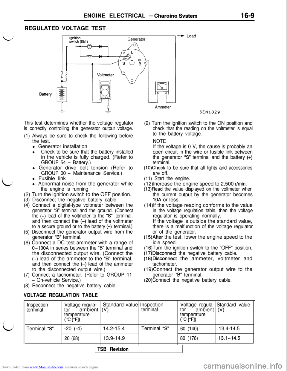
Downloaded from www.Manualslib.com manuals search engine ENGINE ELECTRICAL - Charging Svstem16-9REGULATED VOLTAGE TEST
\:
b
Ignitionswitch (IGl)Generator
This test determines whether the voltage regulator
is correctly controlling the generator output voltage.
(1) Always be sure to check the following before
the test.l Generator installation
lCheck to be sure that the battery installedin the vehicle is fully charged. (Refer to
GROUP 54 - Battery.)l Generator drive belt tension (Refer to
GROUP 00 - Maintenance Service.)l Fusible link
l Abnormal noise from the generator while
the engine is running(2) Turn the ignition switch to the OFF position.
(3) Disconnect the negative battery cable.
(4) Connect a digital-type voltmeter between the
generator “S” terminal and the ground. (Connect
the
(+) lead of the voltmeter to the “s” terminal,
and then connect the (-) lead of the voltmeter
to a secure ground or to the battery (-) terminal.)
(5) Disconnect the generator output wire from the
generator
“B” terminal.(6) Connect a DC test ammeter with a range of
O-100A in series between the “B” terminal andthe disconnected output wire. (Connect the
(+) lead of the ammeter to the “B” terminal,
and then connect the (-) lead of the ammeter
to the disconnected output wire.)
(7) Connect a tachometer. (Refer to GROUP 11
- On-vehicle Service.)
(8) Reconnect the negative battery cable.
VOLTAGE REGULATION TABLE
Ammeter
- Load
6EN1029
(9) Turn the ignition switch to the ON position and
check that the reading on the voltmeter is equal
to the battery voltage.
NOTE
If the voltage is 0 V, the cause is probably an
open circuit in the wire or fusible link between
the generator
“S” terminal and the battery (+)
terminal.
(1O)Check to be sure that all lights and accessories
are off.
(11) Start the engine.(12)lncrease the engine speed to 2,500
r/min.
(13)Read the value displayed on the voltmeter when
the current output by the generator becomes
10A or less.
(14)lf the voltage reading conforms to the value
in the voltage regulation table, then the voltage
regulator is operating normally.If the voltage is outside the standard value,
there is a malfunction of the voltage regulator
or of the generator.
(15)After the test, lower the engine speed to the
idle speed.
(16)Turn the ignition switch to the “OFF” position.
(17)Disconnect the negative battery cable.
(18)Disconnect the ammeter, voltmeter and
tachometer.(19)Connect the generator output wire to the
generator “B” terminal.
(20)Connect the negative battery cable.
Inspection
terminal
Terminal “S”
Voltage regula-Standard value Inspection
torambient (V)terminal
temperature
(“C PI)-20 (-4)14.2-15.4
Terminal “S”
20 (68)13.9-14.9
TSB Revision
Voltage regula- Standard value
torambient (V)
temperature(“c
PI)
60 (140)13.4-14.5
80 (176)13.1-14.5
I
Page 457 of 738
Downloaded from www.Manualslib.com manuals search engine ENGINE ELECTRICAL - Charging System16-11
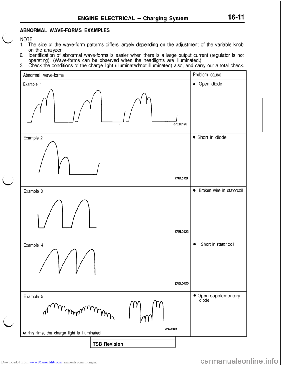
ABNORMAL WAVE-FORMS EXAMPLES
NOTE
1.The size of the wave-form patterns differs largely depending on the adjustment of the variable knob
on the analyzer.
2.Identification of abnormal wave-forms is easier when there is a large output current (regulator is not
operating). (Wave-forms can be observed when the headlights are illuminated.)
3.Check the conditions of the charge light (illuminated/not illuminated) also, and carry out a total check.
Abnormal wave-formsProblem cause
Example 1l Open diode
AALZELOlZO
Example 20 Short in diodeZ7EL0121
Example 30Broken wire in statorcoil
27EL0122
Example 40Short in stator coil
Z7EL0123
Example 5
1 r2rrirl
0 Open supplementarydiode
27EL01244t this time, the charge light is illuminated.
TSB Revision
Page 501 of 738
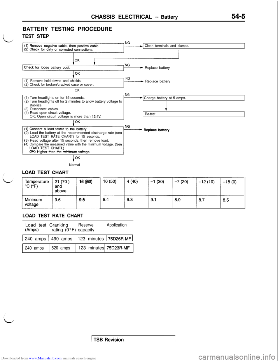
Downloaded from www.Manualslib.com manuals search engine CHASSIS ELECTRICAL - Battery54-5BATTERY TESTING PROCEDURE
LTEST STEP
Clean terminals and clamps.
- Replace battery
(1) Remove hold-downs and shields.(2) Check for broken/cracked case or cover.
OK
NG- Replace battery
(1) Turn headlights on for 15 seconds.
NG(2) Turn headlights off for 2 minutes to allow battery voltage to- Charge battery at 5 amps.
stabilize.
(3) Disconnect cables.(4) Read open circuit voltage.
IOK: Open circuit voltage is more than
12.4V.Re-test(2) Load the battery at the recommended discharge rate (see
LOAD TEST RATE CHART) for 15 seconds.(3) Read voltage after 15 seconds, then remove load.
(4) Compare the measured value with the minimum voltage. (SeeOK: Higher than the minimum voltage
i
Normal
LL16 (60)
9.5
LOAD TEST RATE CHARTLoad test Cranking
Reserve
W-w)rating (0°F) capacity
Application
1 240 amps / 490 amps / 123 minutes 1 75D26R-MF 1
240 amps520 amps123 minutes 75D23R-MF
1 TSB Revision1
Page 506 of 738
Downloaded from www.Manualslib.com manuals search engine 54-I 0CHASSIS ELECTRICAL - Meters and Gauges
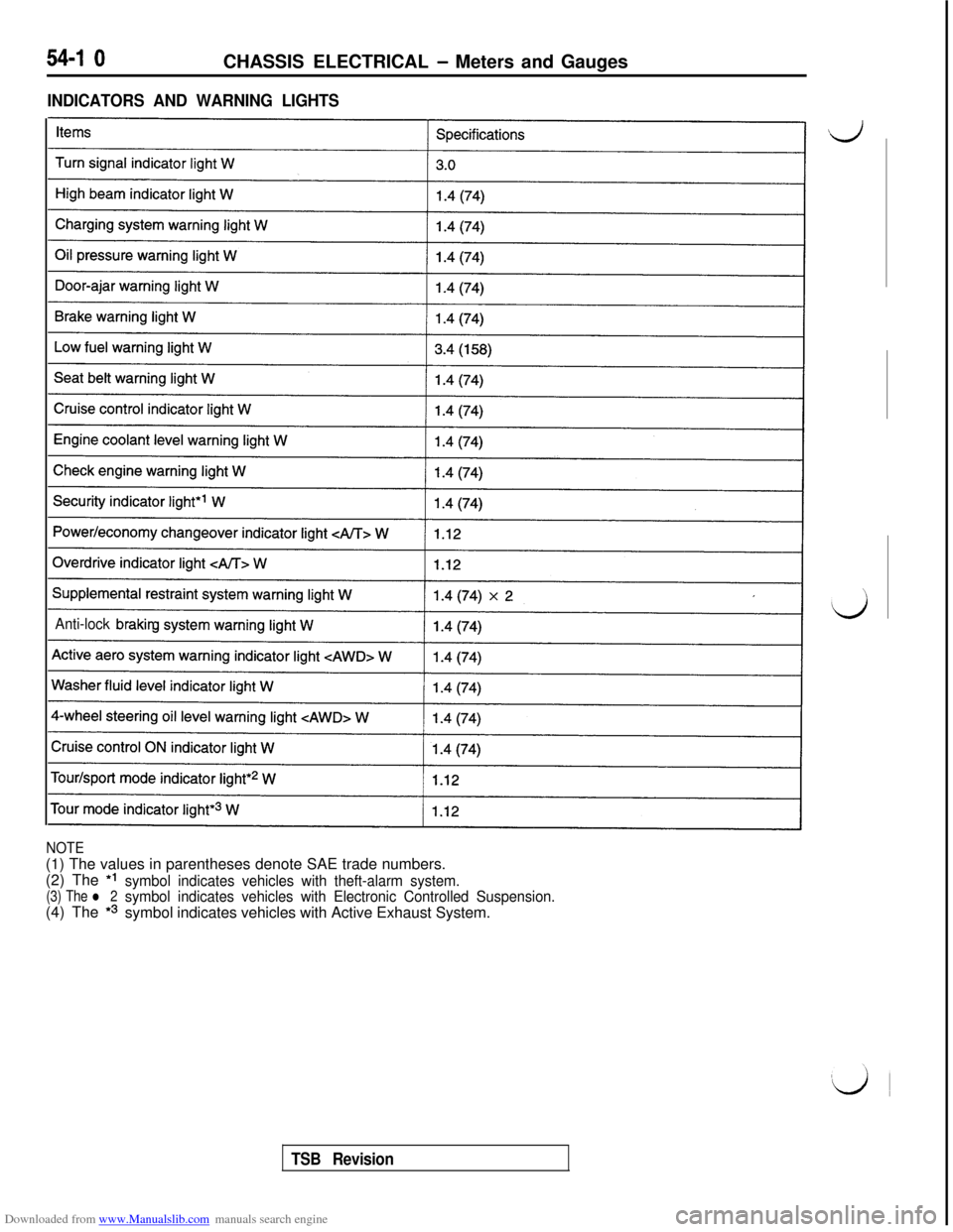
INDICATORS AND WARNING LIGHTS
Anti-lock brakin
NOTE(1) The values in parentheses denote SAE trade numbers.
(2) The *I
(3) The l 2symbol indicates vehicles with theft-alarm system.(4) The
*3
symbol indicates vehicles with Electronic Controlled Suspension.symbol indicates vehicles with Active Exhaust System.
TSB Revision
Page 514 of 738
Downloaded from www.Manualslib.com manuals search engine 54-18CHASSIS ELECTRICAL - Meters and Gauges
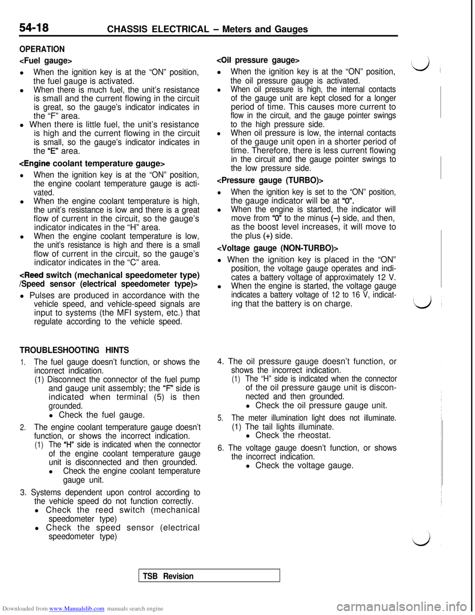
OPERATION
When the ignition key is at the “ON” position,the fuel gauge is activated.
l
When there is much fuel, the unit’s resistanceis small and the current flowing in the circuit
is great, so the gauge’s indicator indicates inthe “F” area.
l When there is little fuel, the unit’s resistance
is high and the current flowing in the circuit
is small, so the gauge’s indicator indicates inthe
“E” area.
lWhen the ignition key is at the “ON” position,
the engine coolant temperature gauge is acti-
vated.l
When the engine coolant temperature is high,
the unit’s resistance is low and there is a greatflow of current in the circuit, so the gauge’s
indicator indicates in the “H” area.
l
When the engine coolant temperature is low,
the unit’s resistance is high and there is a smallflow of current in the circuit, so the gauge’s
indicator indicates in the “C” area.
vehicle speed, and vehicle-speed signals areinput to systems (the MFI system, etc.) that
regulate according to the vehicle speed.
TROUBLESHOOTING HINTS
1.The fuel gauge doesn’t function, or shows the
incorrect indication.
(1) Disconnect the connector of the fuel pumpand gauge unit assembly; the ‘F” side is
indicated when terminal (5) is then
grounded.l Check the fuel gauge.
2.The engine coolant temperature gauge doesn’t
function, or shows the incorrect indication.
(1)The “l-l” side is indicated when the connector
of the engine coolant temperature gauge
unit is disconnected and then grounded.l
Check the engine coolant temperature
gauge unit.
3. Systems dependent upon control according to
the vehicle speed do not function correctly.l Check the reed switch (mechanical
speedometer type)l Check the speed sensor (electrical
speedometer type)
coil pressure gauge>l
When the ignition key is at the “ON” position,
the oil pressure gauge is activated.
lWhen oil pressure is high, the internal contacts
of the gauge unit are kept closed for a longerperiod of time. This causes more current to
flow in the circuit, and the gauge pointer swings
to the high pressure side.
lWhen oil pressure is low, the internal contactsof the gauge unit open in a shorter period of
time. Therefore, there is less current flowing
in the circuit and the gauge pointer swings to
the low pressure side.
lWhen the ignition key is set to the “ON” position,the gauge indicator will be at
“0”.l
When the engine is started, the indicator will
move from
“0” to the minus (-) side, and then,as the boost level increases, it will move to
the plus
(+) side.
position, the voltage gauge operates and indi-
cates a battery voltage of approximately 12 V.l
When the engine is started, the voltage gauge
indicates a battery voltage of 12 to 16 V, indicat-ing that the battery is on charge.
4. The oil pressure gauge doesn’t function, or
shows the incorrect indication.
(1)The “H” side is indicated when the connectorof the oil pressure gauge unit is discon-
nected and then grounded.l Check the oil pressure gauge unit.
5.The meter illumination light does not illuminate.
(1) The tail lights illuminate.l Check the rheostat.
6. The voltage gauge doesn’t function, or shows
the incorrect indication.l Check the voltage gauge.
TSB Revision