light MITSUBISHI 3000GT 1992 2.G Workshop Manual
[x] Cancel search | Manufacturer: MITSUBISHI, Model Year: 1992, Model line: 3000GT, Model: MITSUBISHI 3000GT 1992 2.GPages: 738, PDF Size: 35.06 MB
Page 619 of 738
Downloaded from www.Manualslib.com manuals search engine LCHASSIS ELECTRICAL
- Cigarette Lighter
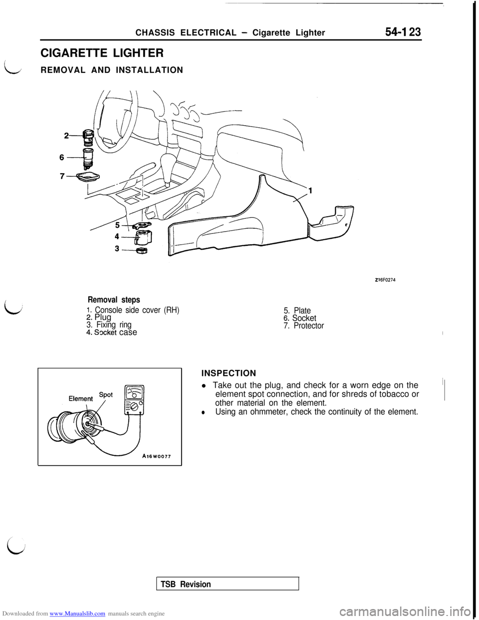
CIGARETTE LIGHTER
REMOVAL AND INSTALLATION54-I 23
i,
216FO274
Removal steps
1. Console side cover (RH)2. Plug3. Fixing ring4. Socket case
5. Plate6. Socket7. ProtectorINSPECTION
l Take out the plug, and check for a worn edge on the
element spot connection, and for shreds of tobacco or
other material on the element.
lUsing an ohmmeter, check the continuity of the element.
TSB Revision
Page 633 of 738
Downloaded from www.Manualslib.com manuals search engine CHASSIS ELECTRICAL - Radio and Tape Player
54-137 ~
L;
(c-(c-34)(c-57)00(D-36),(D-47)(F-06) FTC9
i
~~l~~[~!~~l~ -1
(F-33)(1czD2
Bfzi%$pJ q
HR14M03AB
J/BRADIO REMOTE
CONTROL SWITCHJ/B
3Y
_------
!
(Y-W)
3(1
I
CLOCK
SPRING
I
*m
(UP TO 1995Y
(Fgyiiz/g~-
MODELS).FULL AUTO A/C4----1I
I
RADIO REMOTE
CONTROL SWITCH'T;Tk\IGHT
-T-2R-W
IRADIO AND TAPE PLAYERIIII
------1
(T)Y-
;-----.
@$* -=.------)E
(T>Y-L 2(T>GR-1
(c-34),>3E-----_
(T)Y-L(T>GR-'L
------11
(T)GR-I(T>Y-IR (T>GR-R22
+-
(LH)
- ------- ----------------------‘i1
r 1
7
r
12
i%A'CPR (T)GR-R.FULL AUB-Y.MANUAL I.ELC-4A/i
-;t_310_----_,,21> B-Y
B-Y
lhll (c-15)
B-YjE;EW&AND
.FOG LIGHT
B-Y12
4m7+-RHEOSTAT(RH)\Y/
REAR
SPEAKER
1 TSB Revision
Page 639 of 738
Downloaded from www.Manualslib.com manuals search engine CHASSIS ELECTRICAL - Radio and Tape Player54-143
i@;X&GHT
-i-q-
.HEATER.MANUAL A/C.FULL AUTO A/C
RADIO AND
TAPE PLAYER
L1
------.
Y
t
L
. .i
t
(D-47)
B-E
1
CLOCK
SPRING
_IB-k
0
?ADIO REMOTE:ONTROL SWITCHRADIO REMOTE
CONTROL SWITCH
0-Y
RHE
3
---212.FULL AUTO A/C.MANUAL A/C.ELC-4A/T
1
.1 (c-15)
. ,$&AND
.FOG LIGHT
'TAT
HR14M04BB
TSB Revision
Page 645 of 738
Downloaded from www.Manualslib.com manuals search engine CHASSIS ELECTRICAL - Radio and Tape Player
RADIO REMOTE
CONTROL SWITCHKK1
1.25R-kr
@
GHT
1
;@ATED
i
I6CLOCKSPRINGJ/B
r
. FULL AUTO A/C
G-WG-W
. HEATER. MANUAL A/CG-W
. FULL AUTO A/C
. MANUAL A/C
. ELC-4A/T
1B-Y RADIO AND TAPE PLAYER
i
I-----_OV -“,----_-v------281
(T)Y-LCT) GY-:LCT> Y-li(T>GY-I
_---_----___--____7
(c-34),: .,~1363_-----_------__------
(T>Y-L(T>GR-LCT> Y-F(T> GY-I
_----__------.(F-44)>? q'-.------15161718B-k
(T>Y-L 2(T)GR-ICT> Y-F(T>GR-F
B-Y1
-m
1:2/\
mz7LL/-I:
+-/+
(LH)(RH)\/
RHEOSTAT
,l (c-15)
. b&&&AND
. FOG LIGHTB-Y
1
REAR
SPEAKER
(c-15)(c-34)(c-57)00(D-36)(D-47)(F-06)
c ~~~~1~1~~~
(F-33)Fm)
mB(iisiEa
HR14MOGAB
TSB Revision
Page 656 of 738
Downloaded from www.Manualslib.com manuals search engine 54-160CHASSIS ELECTRICAL - Radio and Tape Player
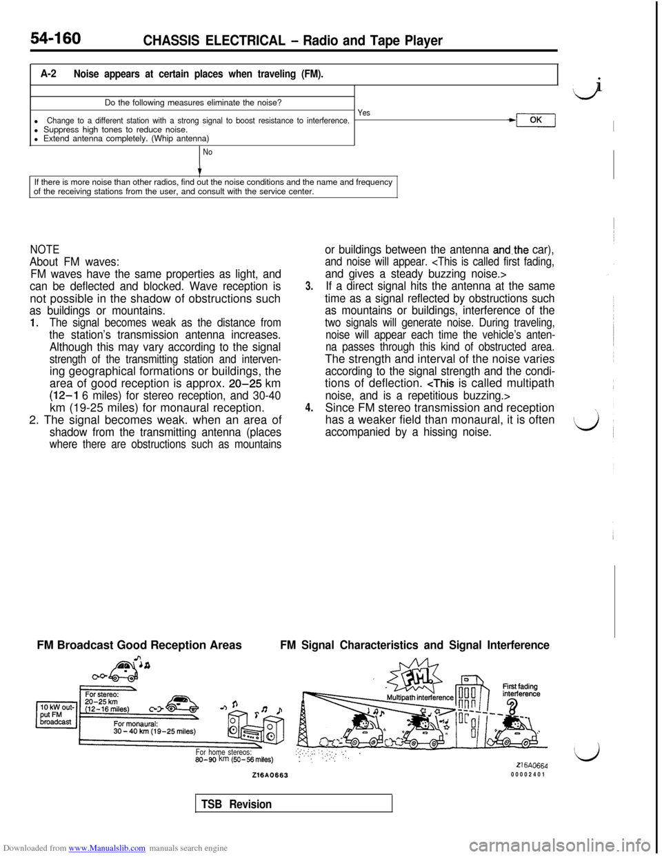
A-2Noise appears at certain places when traveling (FM).Do the following measures eliminate the noise?
YeslChange to a different station with a strong signal to boost resistance to interference.l Suppress high tones to reduce noise.+3cll Extend antenna completely. (Whip antenna)
No
tIf there is more noise than other radios, find out the noise conditions and the name and frequency
of the receiving stations from the user, and consult with the service center.
NOTE
About FM waves:
FM waves have the same properties as light, and
can be deflected and blocked. Wave reception isnot possible in the shadow of obstructions such
as buildings or mountains.
1.The signal becomes weak as the distance from
the station’s transmission antenna increases.
Although this may vary according to the signal
strength of the transmitting station and interven-ing geographical formations or buildings, the
area of good reception is approx.
20-25 km
(12-l 6 miles) for stereo reception, and 30-40km (19-25 miles) for monaural reception.
2. The signal becomes weak. when an area of
shadow from the transmitting antenna (places
where there are obstructions such as mountains
3.
4.
or buildings between the antenna and.the car),
and noise will appear.
If a direct signal hits the antenna at the same
time as a signal reflected by obstructions such
as mountains or buildings, interference of the
two signals will generate noise. During traveling,
noise will appear each time the vehicle’s anten-
na passes through this kind of obstructed area.The strength and interval of the noise varies
according to the signal strength and the condi-tions of deflection.
has a weaker field than monaural, it is often
accompanied by a hissing noise.FM Broadcast Good Reception Areas
FM Signal Characteristics and Signal Interference
For home stereos:80-90 km (SO-56 miles):.:,.::..:,.::.‘; .: ‘, “.‘l’.. ”216AO664Z16A066300002401
Iji
I
TSB Revision
Page 658 of 738
Downloaded from www.Manualslib.com manuals search engine 54-I 62CHASSIS ELECTRICAL - Radio and Tape Player
A-4
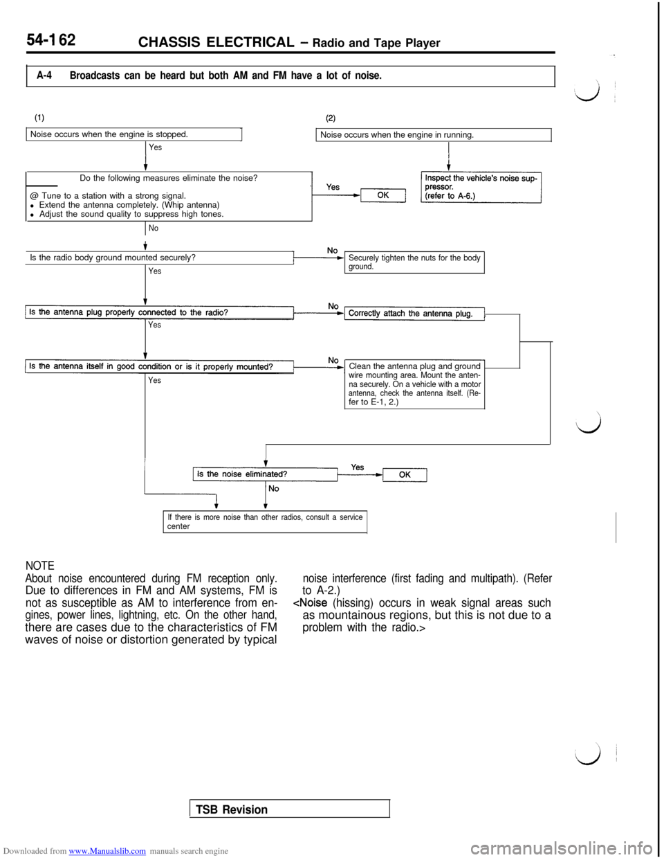
Broadcasts can be heard but both AM and FM have a lot of noise.
(1)Noise occurs when the engine is stopped.
YesJ
(2)Noise occurs when the engine in running.
Do the following measures eliminate the noise?
@ Tune to a station with a strong signal.
l Extend the antenna completely. (Whip antenna)
l Adjust the sound quality to suppress high tones.
NoIs the radio body ground mounted securely?
Yes
Securely tighten the nuts for the bodyground.
Yes
YesClean the antenna plug and ground
wire mounting area. Mount the anten-
na securely. On a vehicle with a motor
antenna, check the antenna itself. (Re-fer to E-1, 2.)
If there is more noise than other radios, consult a servicecenter
NOTE
About noise encountered during FM reception only.
Due to differences in FM and AM systems, FM is
noise interference (first fading and multipath). (Refer
to A-2.)
not as susceptible as AM to interference from en-
gines, power lines, lightning, etc. On the other hand,
TSB Revision
Page 659 of 738
Downloaded from www.Manualslib.com manuals search engine CHASSIS ELECTRICAL - Radio and Tape Plavers54-163 ~
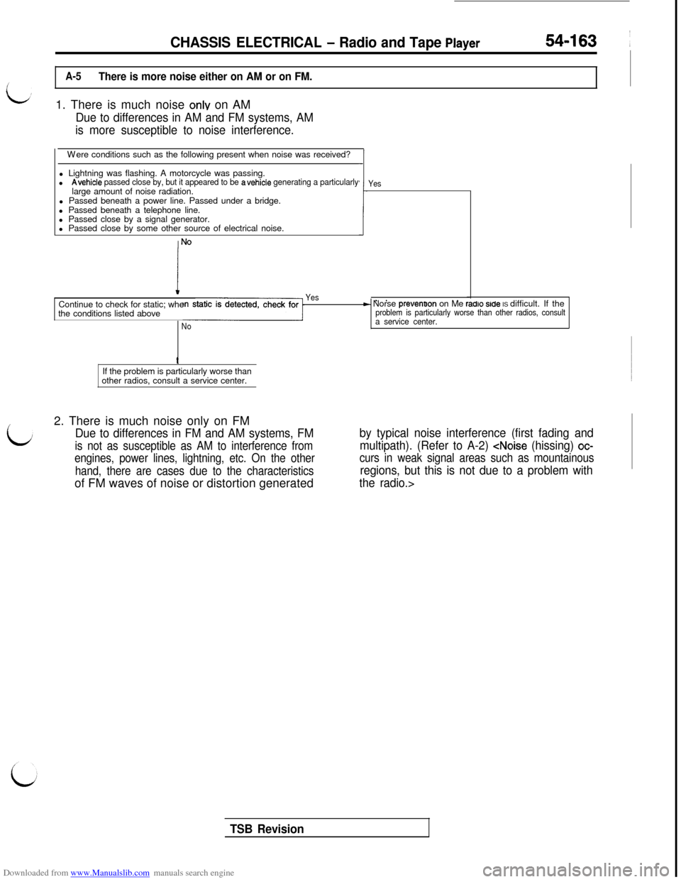
A-5There is more noise either on AM or on FM.1. There is much noise
onlv on AM
Due to differences in AM and FM systems, AM
is more susceptible to noise interference.Were conditions such as the following present when noise was received?
l Lightning was flashing. A motorcycle was passing.
l
Avehicle passed close by, but it appeared to be avehicle generating a particularlylarge amount of noise radiation.
l Passed beneath a power line. Passed under a bridge.
l Passed beneath a telephone line.
l Passed close by a signal generator.
l Passed close by some other source of electrical noise.
.I-!
I
NO
Yes
. .F- Norse prevenoon on Me radro srde IS difficult. If theproblem is particularly worse than other radios, consulta service center.Continue to check for static; whe
the conditions listed aboveNoYest
If the problem is particularly worse than
other radios, consult a service center.
2. There is much noise only on FM
Due to differences in FM and AM systems, FM
is not as susceptible as AM to interference from
engines, power lines, lightning, etc. On the other
hand, there are cases due to the characteristicsof FM waves of noise or distortion generated
by typical noise interference (first fading and
multipath). (Refer to A-2)
regions, but this is not due to a problem with
the radio.>
TSB Revision
Page 663 of 738
Downloaded from www.Manualslib.com manuals search engine CHASSIS ELECTRICAL - Radio and Tape Player54-167
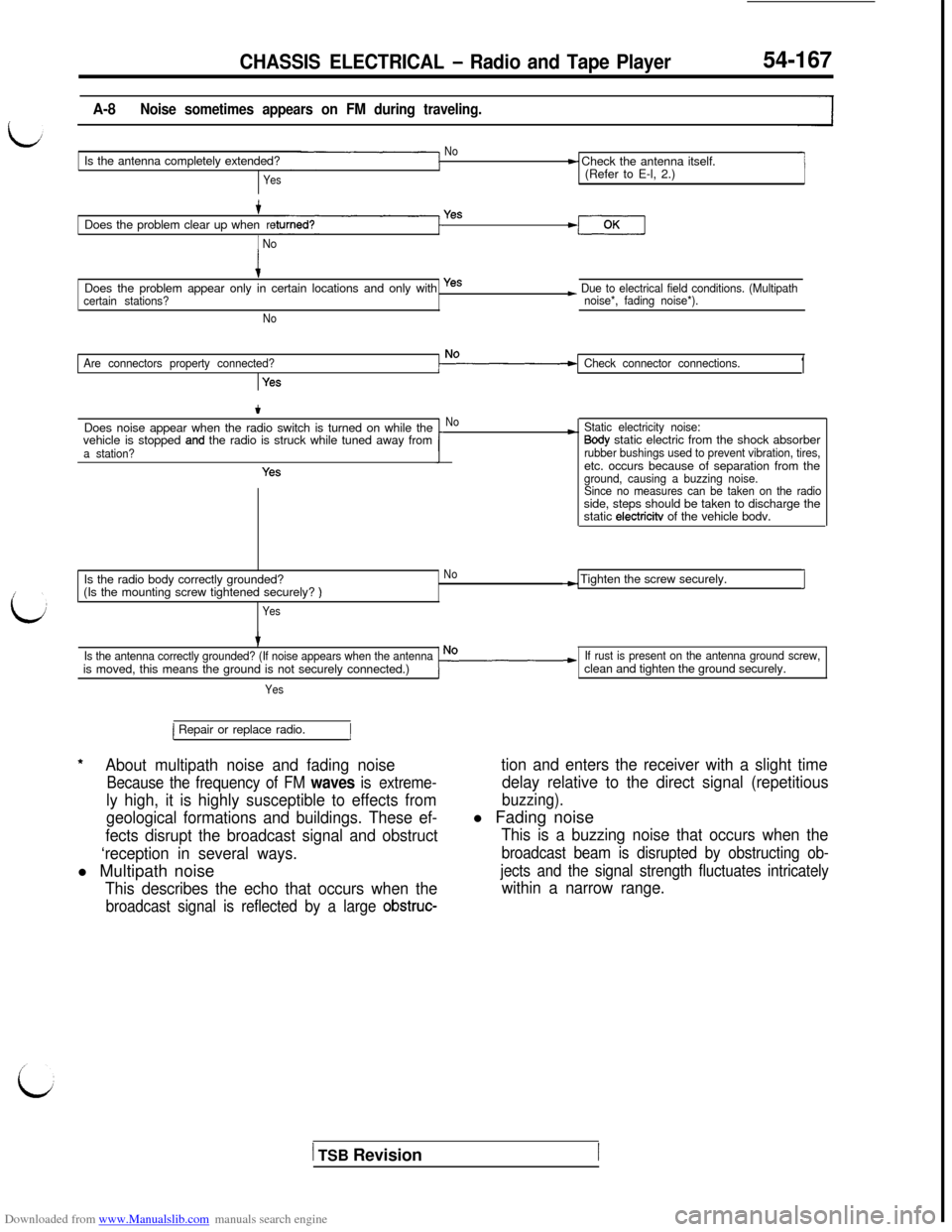
A-8Noise sometimes appears on FM during traveling.
NoIs the antenna completely extended?
Yes
t Check the antenna itself.
(Refer to E-l, 2.)
+Does the problem clear up whenre
1 No
Yes
iDoes the problem appear only in certain locations and only with yes
certain stations?
No
~ Due to electrical field conditions. (Multipath
noise*, fading noise*).
Are connectors property connected?
Yes
Check connector connections.1
tDoes noise appear when the radio switch is turned on while the
vehicle is stopped
and the radio is struck while tuned away froma station?
Yes
No*Static electricity noise:Sody static electric from the shock absorberrubber bushings used to prevent vibration, tires,etc. occurs because of separation from the
ground, causing a buzzing noise.
Since no measures can be taken on the radioside, steps should be taken to discharge the
static
electricitv of the vehicle bodv.
Is the radio body correctly grounded?
No(Is the mounting screw tightened securely?
)
Yes
-) Tighten the screw securely.I
Is the antenna correctly grounded? (If noise appears when the antennais moved, this means the ground is not securely connected.)
Yes
If rust is present on the antenna ground screw,clean and tighten the ground securely.
*
1 Repair or replace radio.1
About multipath noise and fading noise
Because the frequency of FM waves is extreme-
ly high, it is highly susceptible to effects from
geological formations and buildings. These ef-
fects disrupt the broadcast signal and obstruct
‘reception in several ways.l Multipath noise
This describes the echo that occurs when the
broadcast signal is reflected by a large obstruc-
tion and enters the receiver with a slight time
delay relative to the direct signal (repetitious
buzzing).l Fading noise
This is a buzzing noise that occurs when the
broadcast beam is disrupted by obstructing ob-
jects and the signal strength fluctuates intricately
within a narrow range.
1 TSB Revision
Page 686 of 738
Downloaded from www.Manualslib.com manuals search engine CHASSIS ELECTRICAL - Radio and Tape Player
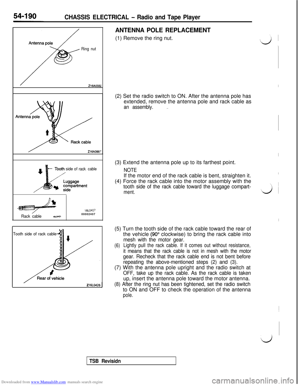
Ring nut
Tbothsideofrack cable
Rack cable
16LO42700002407,8Loa1
7
Tooth side of rack cable
ANTENNA POLE REPLACEMENT(1) Remove the ring nut.
(2) Set the radio switch to ON. After the antenna pole has
extended, remove the antenna pole and rack cable as
an assembly._.(3) Extend the antenna pole up to its farthest point.
NOTEIf the motor end of the rack cable is bent, straighten it.
(4) Force the rack cable into the motor assembly with the
tooth side of the rack cable toward the luggage compart-
ment.(5) Turn the tooth side of the rack cable toward the rear of
the vehicle
(90” clockwise) to bring the rack cable into
mesh with the motor gear.
(6)Lightly pull the rack cable. If it comes out without resistance,
it means that the rack cable is not in mesh with the motor
gear. Recheck that the rack cable end is not bent before
repeating the above-mentioned steps (2) and (3).(7) With the antenna pole upright and the radio switch at
OFF, take up the rack cable. As the rack cable is takenup, insert the antenna pole toward the motor antenna.
(8) After the ring nut has been tightened, set the radio switchto ON and OFF to check the operation of the antenna
pole.
I
I
I
vi ~
I~
d
TSB Revisidn
Page 691 of 738
Downloaded from www.Manualslib.com manuals search engine CHASSIS ELECTRICAL - Rear Window Defogger54-195
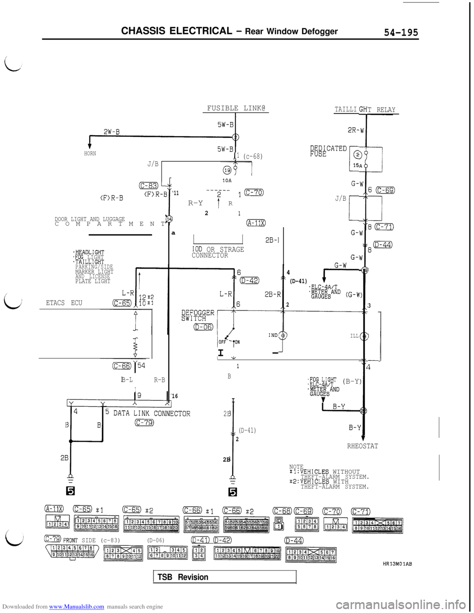
5W-B2W-B
HORN5W-B,,l (c-68)J/B
(c-83)-10A
(F)R-B(F>R-E
DOOR LIGHT AND LUGGAGECOMPARTMENT
‘11----__
R-Y
I' R
1ma
21)(A-11X)
i
FUSIBLE LINK@I
.HEADLIGHT.FOG LIGHT.TAILLIGHT
PARKING/SIDE
MARKER LIGHTAND LICENSEPLATE LIGHT
ETACS ECU
B-L
I
R-B
E
2E4
B
1
6
2B-1
IOD OR STRAGECONNECTOR
lOFd,ONIND’I-
TAILLIGH'T RELAY
2R-
Zz&P”‘“”
L
G
15
G-
J/B
I
G-
G-W4
(D-41)F-.ELC-4A/T
'#&AND (G-!'I
2
1ILL
1 *
1
B
16I
2B
I
(D-41)
2
2B
=
H
:;f'g-$;T (B-Y
*G"~$&AND
v
1
3
1
i-
S(c-69)
II
e(c-71)
RHEOSTAT
NOTE:l:VEHICLES WITHOUTTHEFT-ALARM SYSTEM.X2:VEHICLES WITHTHEFT-ALARM SYSTEM.
(C-79)FRONT SIDE (c-83)(D-06)(D-41) (D-42)(D-44)
HR13MOlAB
TSB Revision